KVS EKODIVIZE KVS MORAVIA VSP-9106 User manual

INSTALLATION,
OPERATION AND
MAINTENANCE MANUAL
SOLID FUEL COOKING APPLIANCE
WITH EXCHANGER
TYPE VSP-9106
Dear customer,
you have purchased a cooking appliance with an exchanger under KVS MORAVIA
trade mark. The product type, including the serial number, is shown on the back of
this manual. In order for the product to serve you well, it is necessary to read this
manual carefully before installing and using it.
Damage caused by incorrect installation or use of incorrect fuel and overloading of
the appliance is not covered by the warranty. According to the safety regulations for
the equipment, the buyer and operator are obliged to familiarise themselves with
the correct operation as described in the operating instructions.

KVS EKODIVIZE a.s. plant Dvorce Manual for Type 9106
Issued 1/2020 2 2

KVS EKODIVIZE a.s. plant Dvorce Manual for Type 9106
Issued 1/2020 3 3
TABLE OF CONTENTS
MANUFACTURER DECLARATION ............................................................ 4
PRODUCT INFORMATION LIST ................................................................ 4
IMPORTANT INFORMATION, BINDING INSTRUCTIONS AND
RECOMMENDATIONS ............................................................................. 5
TECHNICAL SPECIFICATIONS ................................................................... 6
DESCRIPTION - TYPE VSP-9106 ............................................................... 8
DIMENSIONS ........................................................................................... 9
DESCRIPTION OF THE APPLIANCE AND ITS PARTS................................ 10
APPLIANCE INSTALLATION .................................................................... 14
SAFETY INSTRUCTIONS ......................................................................... 15
INSTALLATION IN THE HOT-WATER SYSTEM ........................................ 16
OPERATION AND CONTROL .................................................................. 18
CLEANING AND MAINTENANCE............................................................ 19
FAULT CONDITIONS .............................................................................. 21
PACKAGING RECYCLATION AND DISPOSAL........................................... 21
DISPOSAL OF THE APPLIANCE AFTER ITS SERVICE LIFE ........................ 21

KVS EKODIVIZE a.s. plant Dvorce Manual for Type 9106
Issued 1/2020 4 4
MANUFACTURER DECLARATION
The product is certified according to EN 12815:2001/A1:2004 and complies with the
Commission Regulation ECODESIGN 2015/1185 for solid fuel local space heaters.
Based on this, a Declaration of Performance No. 9106/2019 is issued.
PRODUCT INFORMATION LIST
Name of supplier KVS EKODIVIZE a.s.
ID VSP-9106
Energy Efficiency Class A+
Direct heat output 2,9 kW
Indirect heat output 5,5 kW
Energy efficiency index 110
Energy Efficiency at NHO 82.7%
For preventive measures during assembly, installation and maintenance, see the
manual.
Note: The manufacturer reserves the right to make minor changes arising from
innovative or technical changes to the product and in connection with compliance
with applicable regulations and laws.

KVS EKODIVIZE a.s. plant Dvorce Manual for Type 9106
Issued 1/2020 5 5
IMPORTANT INFORMATION, BINDING INSTRUCTIONS AND RECOMMENDATIONS
All the local regulations including regulations concerning national and
European standards must be observed during installation of the appliance.
Consult the rules of installation and use of the appliance with your
supplier and/or the competent local authorities.
To ensure proper functioning of the appliance, ensure sufficient chimney
draught, see the technical parameters.
The appliance must not be installed in the buildings under construction due
to higher requirements for heating of such spaces. Continuous overheating
could occur and would cause permanent damage to the individual parts.
Corrosion may occur in wet conditions. It is more likely that the appliance
will be operated by a person not acquainted with the manual and possibly
contrary to the instructions in the manual.
An appliance with a heat exchanger cannot be operated without
connection to a functional hot water system. The exchanger could be
overheated and thus irreversibly damaged!!!
No flammable liquids should be used either during the heating process or to
increase the performance of the appliance.
The appliance must not be used for the waste combustion, only
recommended fuels may be used.
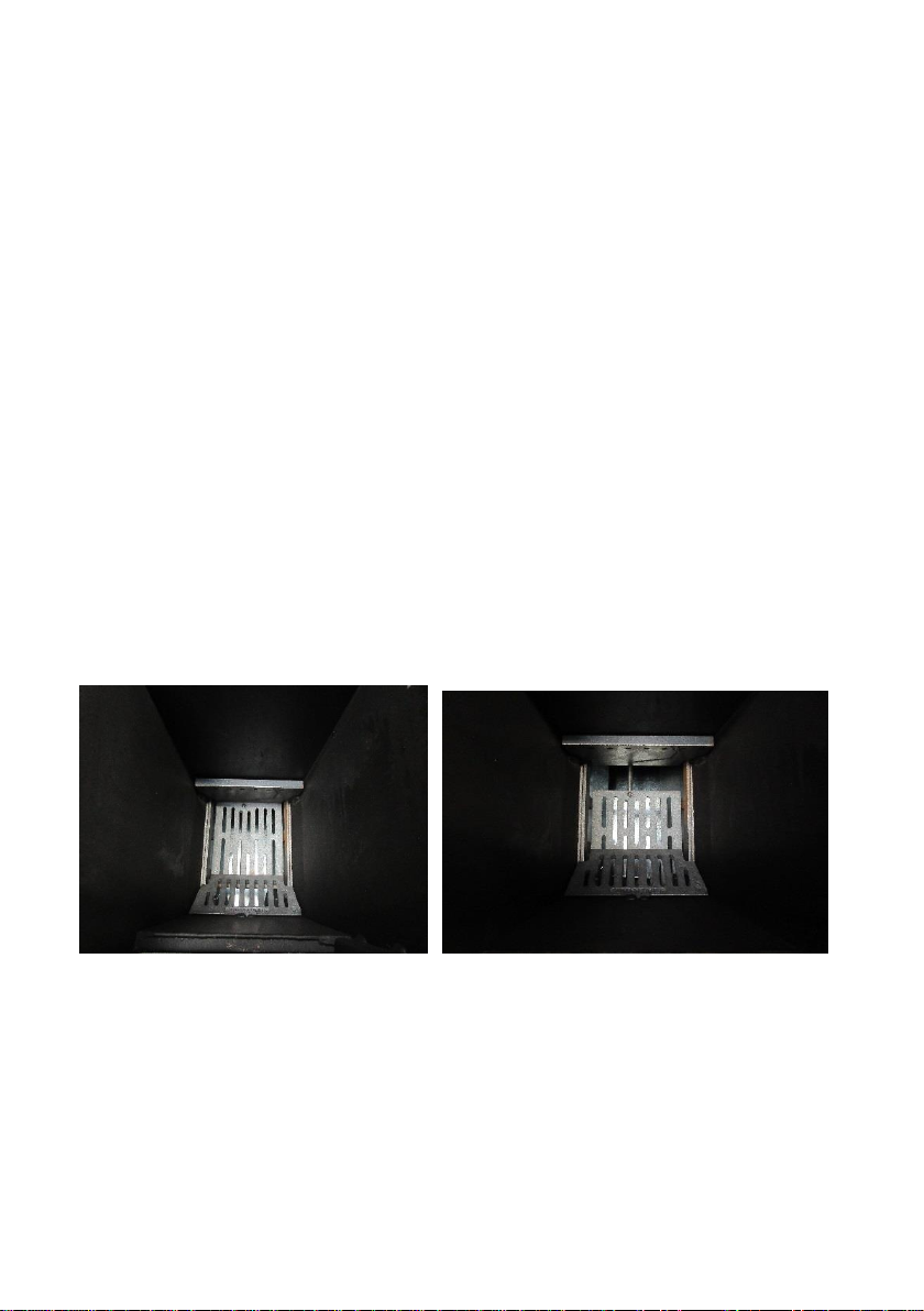
The ashtray door must be closed during the operation and the fire box door
may be opened only when adding fuel or grating in order to prevent the
combustion gases from leaking.
The ash must be filled in non-combustible containers provided with lids! Be
very careful when removing hot ash.
Observe the principles of fire safety.
Do not use damaged (non-functional) appliances.
If the operating conditions are not observed, some parts of the appliance
may be damaged. Thermal overloading of the appliance is forbidden.
If a defect covered by the warranty occurs during the warranty period, do
not correct it yourself and contact your dealer. The list of parts that can be
replaced by the consumer is included in the manual on the page 19.
Only original parts approved by the manufacturer should be used.
Unauthorized modifications of the appliance are prohibited.
It is forbidden to cover the hob top plate in any way if the appliance is in
operation!!
The appliance may be operated by adults only. Never leave the appliance
in operation unattended. Children must not operate the appliance nor stay
nearby the appliance without adult supervision.

KVS EKODIVIZE a.s. plant Dvorce Manual for Type 9106
Issued 1/2020 6 6
TECHNICAL SPECIFICATIONS
Appliance VSP-9106
Energy Efficiency Class A+
Nominal Heat Output (NHO) 8.4 kW
Nominal Heat Input 10.2 kW
Direct Heat Output 2.9 kW
Indirect Heat Output 5.5 kW
Energy Efficiency Index 110
Energy Efficiency at NHO 82.7%
Seasonal Efficiency 72.7%
Average Flue Gas Temperature at NHO 190°C
Flue Gas Mass Flow Rate at NHO 8.8 g/s
Space Heating Emissions a NHO (with O2 = 13%)
PM 36 mg/m3
OGC 96 mg/m3
CO 1,248 mg/m3
NOx 69 mg/m3
Minimum Flue Draught 12 Pa
Preferred Fuel Wood briquettes
Preferred Fuel Consumption 2.2 kg/h

KVS EKODIVIZE a.s. plant Dvorce Manual for Type 9106
Issued 1/2020 7 7
Height (of the hob top panel) 850 mm
Width 330 mm
Depth 640 mm
Flue Connector Diameter 130 mm
Cooking Range Hob Area 0.12 m2
Cooking Range Hob dimensions 486 x 254 mm
Weight 102 kg
System connection 1“
Heat Water Exchanger Capacity 14 l
Heated Area 150 - 180 m3
Maximum Water Working Overpressure 2 bar
Fire box dimensions:
width x height x depth 228 x 490 x 250 mm
Fire grate: width x length 165 x 205 mm
Stoke hole dimensions: width x height 192 x 135 mm
Accessories
Poker 1 pc

KVS EKODIVIZE a.s. plant Dvorce Manual for Type 9106
Issued 1/2020 8 8
DESCRIPTION - TYPE VSP-9106
Drawing 1
1. Hob Top
2. Fire Box Door
3. Temperature Gauge
4. Grate Handle
5. Ash Door
6. Combustion Air Intake Control

KVS EKODIVIZE a.s. plant Dvorce Manual for Type 9106
Issued 1/2020 9 9
DIMENSIONS
VSP-9106

KVS EKODIVIZE a.s. plant Dvorce Manual for Type 9106
Issued 1/2020 10 10
DESCRIPTION OF THE APPLIANCE AND ITS PARTS
Type VSP-9106 is designed for burning solid fuel (wood, wood briquettes) in periodic
batches for the purpose of home cooking and domestic central heating system,
currently according to CSN EN 12815:2002 and Amendment A1:2005. The appliance
can be connected to the flue only from the rear side. A permanent heating operation
cannot be set and the fuel must be added with the interval of 1-3 hours (i.e. The
appliance is suitable for short operational periods only).
Rooms are heated by radiant heat flowing into the space through the front section,
the hob and the sides. The built-in hot-water exchanger is able to heat the other
rooms using radiators, or to heat the water in a hot-water tank. The hob top is
designed for cooking and the whole surface is heated during operation.
FIRE BOX
The firebox consists of the heat exchanger proper (welded unit with fins), a bearing in
which the grates (sliding, suspended) are located, and a cast iron panel with holes for
the supply of secondary air. The horizontal sliding grating is controlled by moving the
grating lever back and forth, see the Drawing 6. The grating is only moved for cleaning
purposes. By moving it forward, a flow-through hole is formed at the back of the fire
box through which the unburnt fuel residues fall into the ashtray, see the Drawing 3.
During operation, the sliding grating must be fully retracted back, see the Drawing
2; grating is not allowed otherwise the burning fuel could get stuck in the hole!
Drawing 2 Drawing 3
During heating, it is recommended that the fuel is poked from time to time using a
poker to increase the supply of primary combustion air to the fire box. The grating in
the front part of the fire box improves combustion and also serves to improve

KVS EKODIVIZE a.s. plant Dvorce Manual for Type 9106
Issued 1/2020 11 11
cleaning of the burnt fuel, see the Drawing 4. The cast iron plate with holes supplies
the secondary air to the fire box, which guarantees better combustion, see the
Drawing 5.
Drawing 4 Drawing 5 Drawing 6
A cleaning flap is located under the hob top in the back top part of the appliance,
which is removed only for cleaning purposes. During operation, the flap must be
always fully retracted, see the Drawing 7. When the flue gas routes are cleaned,
hold the flap behind the bend and remove it completely, see the Drawing 8.
Drawing 7 Drawing 8
AIR INTAKE REGULATION
The primary air intake regulation is controlled using a combustion air intake control
built in into the ash door, see the Drawing 1, point 5. The air intake can be controlled
by turning the regulator handle, see the Drawing , point 6, to adjust the fuel
combustion speed and appliance performance. The regulation is indicated by
triangles on the ash door (Drawing 9), where the lever positioned under one triangle
means that the air intake is closed for slow burning. On the other hand, in the
position under four triangles the air intake is fully open for fast burning.

KVS EKODIVIZE a.s. plant Dvorce Manual for Type 9106
Issued 1/2020 12 12
Drawing 9 Drawing 10
During the operation of the appliance, the primary combustion air supply must be
ensured to the room in which the appliance is located. We do not recommend to use
air (vapour) suction devices unless the sufficient air supply for burning in the
appliance is provided.
The supply of secondary air flows into the fire box through a cast iron plate with
holes suspended in the back part of the fire box (Drawing 5) and through the fire box
door - a vent in the bottom part of the door heat shield. Secondary air flow cannot be
regulated.
TEMPERATURE GAUGE
A capillary temperature gauge in mounted on the front of the appliance that
measures the temperature of the water in the exchanger using a sensor. The scale is
colour marked, with the green field indicating the ideal operating temperature of the
exchanger (65 –90°C) and the red field indicating the system overheating (90 –
120°C), Drawing 11.
Drawing 11

KVS EKODIVIZE a.s. plant Dvorce Manual for Type 9106
Issued 1/2020 13 13
COOKING RANGE HOB
The cooking range hob is used for cooking and heating of food. It is made of steel and
has a spray of baking paint, Drawing 12.
Drawing 12 –Cooking range hob in the frame
BALL GEAR
The flue pipe with the diameter of 130 mm is located on the rear wall of the
appliance and is a part of the exchanger, Drawing 18.
CLEANING HOLE
The cleaning hole is located in the rear bottom part of the appliance. After removing
the cleaning flap (Drawing 8), the sufficient space is created to remove the cover
(Drawing 13 and Drawing 14).
Drawing 13 Drawing 14

KVS EKODIVIZE a.s. plant Dvorce Manual for Type 9106
Issued 1/2020 14 14
APPLIANCE INSTALLATION
All the local regulations including regulations concerning national and European
standards must be observed during installation of the appliance. The appliance for
solid fuel is intended to be used in the domestic environment. A sufficient supply of
the air necessary for burning must be provided in the room where the appliance is
installed. Do not use air suction devices unless the sufficient air supply for burning in
the appliance is provided.
The necessary condition of the proper operation is a stack with a sufficient draught.
The chimney draft requirements are specified in the technical parameters. It is
recommend to use a chimney with the inner diameter of at least 160 mm and the
min. height of 5 m from the connection to the flue collar. The appliance must be
connected to a separate chimney.
Upon delivery, the appliance is ready to be connected to the household chimney
using a connecting link. The connection to the chimney must comply with the
applicable standards; it should be as short as possible, straight and the connections
must be tight. The appliance does not include a chimney flap; therefore, it is
necessary to connect the appliance to the flue ducting with the chimney flap,
Drawing 15. Install the appliance to ensure adequate access for cleaning the flue
ducting and the chimney. The appliance may only be installed by
authorized persons.
The connection must comply with the national, European, local and
building regulations as well as the fire protection provisions. The
chimney inspection report must be available.
Ensure sufficient access to the chimney and the flue ducting; clean the
appliance several times a year during the operation according to the
applicable regulations. If regular inspection and chimney cleaning are
omitted, the probability of a fire in the chimney increases.
Drawing 15
Right Wrong
Drawing 16 - Connection of the flue ducting to the flue collar (applicable in the Czech
Republic).

KVS EKODIVIZE a.s. plant Dvorce Manual for Type 9106
Issued 1/2020 15 15
SAFETY INSTRUCTIONS
The smallest distance from the combustible materials with the combustibility grade
B, C1, C2, is at least 800 mm in the direction perpendicular to the opening wall, 400
mm from side and 400 mm from behind, Drawing 17. For combustible materials with
the combustibility grade C3and with the unknown combustibility grade, the distance
must be doubled. No flammable objects should be laid on the appliance and should
be kept at a safe distance from it. The appliance must stand on a non-combustible,
heat-insulated mat with the dimensions exceeding the section plan by at least 600
mm in front of the stoke hole and at least 300 mm from the sides of the stoke hole.
During heating, the heat energy is released, which leads to a noticeable heating of
the entire appliance.
Indication of areas where burns may occur:
Hob and hob frame, sidewall
Fire box door and ash door
Control handles
Flue ducting
Make your children aware of the risk of burns!
Drawing 17 –Safe distance sketch for placing the appliance, type VSP-9106

KVS EKODIVIZE a.s. plant Dvorce Manual for Type 9106
Issued 1/2020 16 16
INSTALLATION IN THE HOT-WATER SYSTEM
• The appliance and the exchanger may only be installed by a person authorised to
do so. The correct connection is the responsibility of the performing company or the
user. The appliance with a heat exchanger cannot be operated without heating
medium. The appliance claims caused by unprofessional interventions shall not be
accepted.
Observe the following instructions and recommendations during assembly and
operation:
• Level the appliance.
• Connect the heater exchanger heating and return water connections to the hot-
water system according to the diagram, Drawing 19.
• Due to the limited space of the appliance design, the water-water heat exchanger
dimensions are smaller with a smaller water volume. It is recommended to connect
to the circuit with forced water circulation, i.e. with a pump. Install the pump in the
return water line. In case of power failure, provide a pump drive backup power
supply, otherwise it will be necessary to stop the combustion in the appliance!!
• Connect the 1.8 bar / 3/4” relief valve to the system.
• As close as possible to the outlet from the exchanger, mount the pump
temperature sensor and set the pump switching temperature in the range 65-70°C.
Lower outlet temperature (with respect to a smaller exchanger volume) could cause
insufficient heating of the system.
• It is recommended to set the temperature gradient of 65°C to 55°C or 70°C to 60°C.
• It is recommended to connect two or three heating bodies (radiators) with the
length of 1,200 mm each, and a boiler with the volume of 80-100 l. When connected,
install the valves on each body.
• The entire heating system can be heated simultaneously. If the return water
temperature of at least 55°C is not reached, open the heaters one after another until
the sufficient return water temperature is reached.
• If the radiators are fitted with thermostatic heads, a heat accumulating tank
should be connected to the system.

KVS EKODIVIZE a.s. plant Dvorce Manual for Type 9106
Issued 1/2020 17 17
1. Plus - outlet - warm water
2. Minus - inlet - cold water
3. Flue dusting diameter 130 mm
Figure 18 - VSP-9106 Rear side
Drawing 19

KVS EKODIVIZE a.s. plant Dvorce Manual for Type 9106
Issued 1/2020 18 18
OPERATION AND CONTROL
Before firing the cooker for the first time
Remove the hob, route the packing rope all around the perimeter inside the
frame of the hob and seat the hob back.
The cleaning flap under the hob must be fully pushed towards the rear wall.
Ensure adequate ventilation of the room as protective paint, grease residues
and other materials will be baked.
Check that the grate is clean and in the correct position, i.e. retracted
backwards.
Put a piece of newspaper on the grate, spread small dry softwood chips on
the paper and a few pieces of smaller logs. To facilitate ignition, insert a
piece of paper in the stake hole.
Open the primary air intake on the ash door to the position for the maximum
flow. In case of worse draught conditions, the ignition may be performed
with the ash door slightly open. During further operation, the door must be
closed and the air intake is regulated only using the combustion air intake
control.
It is recommended to use long matches, dry wood chips or a solid fire lighter
for ignition. When the fuel is ignited, close the fire box door.
Once a glowing mat is formed, you can add more fuel.
Set the pump switching temperature in the range of 65 –70°C, open all
radiators or a boiler. When the temperature of the water in the exchanger
reaches the required temperature, the pump is switched on to distribute the
hot water to the radiators. The return water temperature should not drop
below 55°C, otherwise tarring and low temperature corrosion may occur. In
this case, leave the nearest radiator open and close the others. After
reaching the required return water temperature of 55°C, open the radiators
one after another.
Make sure that you do not smother the fire by adding the fuel too fast. Gradually
extend the fuel feed interval. Add the fuel manually. During the first week of use, you
must not overfill the fire box with fuel (up to a maximum of half the fire box height).
Any heat treatment of food is prohibited during the first heating since all parts of the
appliance are baked and the sheets of the skeleton are annealed when the appliance
is running in. Avoid fast heating of the appliance with the excessive load. If the above
conditions are not observed, parts of the appliance may be damaged. Easy visual
check of combustion - no heavy smoke can be seen rising from the chimney (except
the time immediately after stoking up). The capacity of the appliance is regulated by
the amount of fuel added and by the amount of primary air intake under the grate.
Occasionally clean the grate with help of a poker.

KVS EKODIVIZE a.s. plant Dvorce Manual for Type 9106
Issued 1/2020 19 19
Normal operation
Once the appliance is run-in, proceed as in the case of the first heating. The entire
fire box may be used for combustion; a larger amount of fuel may be added
gradually, until the fuel starts falling from the stoke door. If the appliance emits
smoke after the fuel is added, close the primary air intake on the ash door. Open the
stoke door partially to suck the air and only then fully open it and load the fuel. By
loading a larger amount of fuel, you can extend the feeding interval depending on
the type and amount of the fuel. Always make sure that you do not smother the fire
by adding the fuel. During heating, use a poker for grating to support burning.
Cooking on the cooking range hob
The cooking range hob is heated on the entire surface for all the time the appliance is
heated. The temperature of the hob top is influenced by the amount of fuel added
and the air supplied. When overboiling occurs during cooking, it is recommended to
remove larger impurities immediately so that they are not burnt on the hob, and
remove the remaining impurities upon the hob cools down. You should always use
pots with flat bases and metal handles.
CLEANING AND MAINTENANCE
The workmanship quality of the appliance guarantees a long service life, but without
proper operation and maintenance, this lifetime would be difficult to reach. Clean
the entire appliance, the flue ducting and the chimney on a regular basis. Check that
the parts of the appliance and the flue ducting for defects. Cleaning and maintenance
should always be carried out with an appliance completely cooled. After a longer
period of non-operation, perform a preventive inspection of the throughput of the
flue gas routes of the appliance, the flue ducting and the chimney.
List of parts that the consumer can replace (both during the
warranty and post-warranty period) themselves after
consultation with their dealer:
cooking range hob, all seals, cast iron parts
controls such as handles, grips, etc., mounted enamelled parts
Fire place and flue cleaning
Remove the cooking range hob and the cleaning flap (Drawing 7) and
remove any soot with a sweeper or a soot vacuum cleaner.
Remove the cover using a poker (Drawings 13 and 14).

KVS EKODIVIZE a.s. plant Dvorce Manual for Type 9106
Issued 1/2020 20 20
Clean the heat exchanger walls with a sweeper or a soot vacuum cleaner.
Sweep the residues from the cover area into the ashtray or remove them
using a vacuum cleaner.
Move the sliding grate forward and remove the ash residues from the hole
into the ash tray or remove them using a vacuum cleaner.
Once the entire appliance has been cleaned, put the cover back using a
poker and insert the cleaning flap back with the bend upwards.
Open the ash door, empty the tray, sweep out or vacuum clean the bottom
of the appliance and return the ash tray back.
Finally, seat the hob top back into the frame of the hob on a seal spread
around the entire perimeter.
Make sure that all parts are properly seated and perfectly sealed. Check for any
damage to all parts of the heating system.
Cleaning the external surfaces
Clean the painted surfaces using fixtures designed for this purpose, in the
Czech Republic, we recommend the MEFISTO products of Druchema
company. Never use abrasive agents, the enamel would be scratched!
Remove larger impurities using abrasive nonwovens (Drawing 20), which is
part of our offer. Otherwise the TORRO paste from Tatrachema (CR). Finally,
clean the hob with a damp cloth and dry thoroughly. During using the
appliance, apply a thin layer of vegetable or animal fat on the hob.
Cleaning set –(abrasive nonwovens) is
intended for cleaning of the hobs and
the ground stainless steel frame of the
hob. Do not use it to clean any other
parts; scratches may occur.
Grey abrasive nonwovens –for very
fine cleaning
Bordeaux abrasive nonwovens –for
medium-coarse cleaning
Drawing 20 Blue abrasive nonwovens –for larger
impurities, grinds in depth
Table of contents
Popular Stove manuals by other brands

Empire Comfort Systems
Empire Comfort Systems DVP20CC Series Installation instructions and owner's manual

Nordpeis
Nordpeis Havanna user manual

Dimplex
Dimplex CELESTE user guide

Cattara
Cattara TRAVELER instruction manual

Regency
Regency FG39-NG2 Owners & installation manual

Nordpeis
Nordpeis Bergen Installation and user manual