KVS MORAVIA TYPE 9101 Manual

TYPE 9101 07/2014 1
TYPE 9101
OPERATION & MAINTENANCE
MANUAL
INSTALLATION MANUAL
SOLID FUEL
RANGE COOKER

TYPE 9101 07/2014 2

TYPE 9101 07/2014 3
Dear customer,
Thank you or purchasing o the appliance KVS MORAVIA - solid uel range cooker. We trust that
our product serves you well. Some important principles should be observed during its operation.
There ore, in your interest, care ully study this manual and operate the product according to the
given instructions. The 9101 appliance has a manu acturer issued declaration o con ormity
according to Section 12, Article 3, o Law No. 22/1997 o the Czech Republic.
• No lammable liquids should be used when lighting the ire, nor should they be used to
increase the nominal output o the appliance.
• The appliance should not be used or waste incineration; only recommended uels may be
used.
• During operation, the ash tray door should be closed, and the ire door should only be opened
or lighting the ire or raking the grate in order to prevent lue gas bleeding.
• Ash should be put into non- lammable ash bins with covers! Be very care ul during the
removal o hot ash.
• Pay attention to ire sa ety!
• It is orbidden to use the appliance i it is damaged (un it or its unction)!
• Any contravention o the operating conditions may cause damage to some parts o the
appliance. It is recommended not to overload the appliance in any way.
• Poss ble no sy mpacts (popp ng) of the metal plates or ch pp ng of the f red clay l n ng
ns de the appl ance are not subject to repa r or a cla m procedure. The cause of these
mpacts s the nternal stress of the metal plates, wh ch w ll fade after a certa n t me ( t
depends on the f r ng frequency). These occurrences endanger ne ther the safety, nor
the funct on of the appl ance.
• Any repair o the appliance, except cleaning and ired claying must only be made by an
authorised worker.
• Local regulations, including those regulations related to national and European standards,
shall be observed during the installation o the appliance.
• It is recommended that you only use spare parts approved by the manu acturer.
• Unauthorised modi ications o the appliance are orbidden.
• The appliance must only be operated by adults, and during operation, the appliance requires
intermittent attendance and supervision.
OPERATION AND MAINTENACE MANUAL
Important Informat on, B nd ng Instruct on
s and Recommendat ons

TYPE 9101 07/2014 4
The TYPE 9101 appliance has been designed or solid uel combustion in periodic eed rates and
is intended or cooking in households and/or or heating the space in which it is situated, accor-
ding to the ČSN EN 12815:2002 Standard as amended by A1:2005. The appliance can be con-
nected to a chimney rom the back, both sides or rom the top by means o a hole in the hob-top
(Figure 1).
The appliance is suitable or short operational periods, so it is not possible to set the permanent-
heat process with a shortest interval o uel supply o 10 hours.
Appl ance TYPE 9101
Nominal heat output (NHO) wood coal
• summer mode 6 kW 6 kW
• winter mode 6 kW 6 kW
E iciency with NHO 73,3%
Average lue gas temperature with NHO 275°C
Flue gas mass low rate with NHO 8,3 g/s
Average concentration o CO with NHO (with O2 = 13%) 0,11 %
Minimum chimney draught 12 Pa
Working sur ace height (distance rom loor to hob top panel) 850 mm
Appliance width 325 mm
Appliance depth 620 mm
Exhaust branch diameter 120 mm
Height to lue centre 700 ± 0.5 mm
Hob-top panels area 0.12 m2
Tested uel wood: size 200-265 mm
Average wood consumption 2 kg/h
Weight 100 kg
D mens ons of the F re Box
Width x Height х Depth (summer regime) 190 х 220 x 270 mm
Width x Height х Depth (winter regime) 190 х 360 x 270 mm
Fire grate, Width х Depth (upper) 185 х 285 mm
Fire grate, Width х Depth (bottom) 140 х 240 mm
Stokehole, Width x Height 192 х 130 mm
Accessor es
Poker 1 piece
Techn c
al S
pec f cat ons

TYPE 9101 07/2014 5
1. Hob-top
2. Cover strip
3. Combustion chamber – door
4. Grate lever (with a sa ety lock)*
5. Ash tray door
6. Air rose
7. Fuel case
* the lock s only n some vers ons
of TYPE 9101 appl ances.
Figure 1
The upper working sur ace comprises a hob-top. The appliance casing is made o enamelled steel
plates. The thermally stressed parts o the appliance are made o cast iron and ired clay.
The appliance can be connected to a chimney rom the back, both sides or rom the top by means
o a hole in the Hob-Top (Fig.1 and 5).
The hotplate lid* is packaged separately behind the rear side o the appliance or ease o
transportation. A ter the appliance has been unpacked, insert the hinge pins into the openings at
the rear section o the hotplate rame. The springs in the hinges assist in keeping the lid in a
vertical position.
*The hotplate l d s suppl ed upon the customer’s request only.
NOTE:
The manu acturer reserves the right to carry out small changes resulting rom innovative or
technical changes o the product that will have no detrimental a ect on the unction o the
appliance.
Descr pt on
and D mens onal Sketch

TYPE 9101 07/2014 6
Fuel
The appliance has been designed or solid uel combustion:
- wood (tested uel),
- recommended uels are brown coal, wood-base waste, lignite briquettes, common commercial
uels. Take care that the uel used is dry. It is recommended that you avoid burning high-calori ic
uels which reduce the service li e o the appliance.
F re grates
The appliance is equipped with two grates – the upper one ( ixed) and the lower one (rotary). The
upper grate is placed in a position which guarantees optimum uel consumption in the summer. In
winter this grate should be removed (Figure 2) and the advantage o increased room o the
combustion chamber should be used. Combustion then takes place on the lower grate which can
be handled using a lever (Figure 3).
Rak ng
Raking must be done so the unburned uel alls to the ash tray below, increasing the combustion
(primary) air supply to the ire again. This must be carried out by holding the grate lever and
dragging it back and orth. Pieces too large to drop can be removed by turning the grate by means
o the lever (Figure 3) a ter ire extinction. Intermittent raking should be done even during heating
on the upper grate using the ire rake.
Note: Some versions are equipped with a rotary grate sa ety lock preventing spontaneous turn o
the grate so it should be unlocked by pressing to the le t (Figure 3) be ore turning the grate.
Figure 2
Serv ce
I
nstruct ons

TYPE 9101 07/2014 7
Figure 3
A r supply control (F gure 4)
The combustion air supply control is carried out by means o an air rose, which is a part o the ash
tray door. By turning it with the lever it is possible to control the air supply and thus a ect the burn-
ing rate o the uel (appliance output). The graphic representation o the control is made using
triangles and the lever under the
▲
symbol means slow burning (air supply is closed) and,
contrariwise, the lever below the symbol
▲▲▲▲
means ast burning (air supply is completely
open) (Figure 4). During the operation o the appliance, the combustion air supply should be
ensured and the air supply hole should not be blocked. In the room where the appliance is
situated, air exhausts should not be used unless an adequate air supply or venting is ensured
Figure 4

TYPE 9101 07/2014 8
Appl ance hob-top
The hob top panel is made rom steel. The ront o the hob-top (above the combustion chamber) is
especially intended or ast cooking, while the rear part has a lower temperature and is suitable or
slow cooking and keeping meals warm. You should always use pots with lat bases.
F g. 5 (dimensions in mm)

TYPE 9101 07/2014 9
When you are iring or the irst time, oodstu s should not be cooked. Ensure the room is well
ventilated as the appliance will burn o its protective painting and at residues.
Be ore beginning, open the ire place door and check whether the grate is clean. Use paper or
the base o the ire, over which small kindling o so t dry wood should be spread. Larger pieces o
dry wood should then be placed on top. Open the air supply under the grate through the air rose.
A ter lighting, close the ire place door and when the ire has caught add more pieces o wood.
When a burning bed o embers has ormed you can stoke additional uel. Be care ul not to
smother the ire by stoking a big amount o uel too quickly. Gradually extend the ignition period
(about 25 minutes or heating at the upper grate and 45 minutes or the lower one). Carry out
re uelling by hand or by means o a suitable shovel.
The appliance output can be controlled by the air supply under the grate. From time to time, purge
the grate using the ire rake. I the appliance emits umes during uelling, close the air intake.
The entire area o the ire place can be used. Take care that the uel does not all out o the ire
place. With poor draught conditions or with poor weather conditions you should use small dry
pieces o wood or uel.
Note: KVS EKODIVIZE Inc strongly recommends that their range cooker should be covered by
the uninsulated lid only a ter the cooker ceased its operation!
That means when the ood is being cooked on the hob, and uel is still being added or heating
purposes, or the burner is simply on, the lid must be kept in the raised position. It can be lowered
to cover the hob only when the cooker is not in operation or inishing its operation (no uel has
been added, the cooker is cooling down and the ire in the burner is burning down).
F re place and flue clean ng
In order to maintain the optimum working condition o the appliance, it is necessary to clean it
regularly. The combustion chamber should always be cleaned when the appliance is out o
service.
Be ore repeated ignition or a ter a longer service interruption, it is necessary to carry out an
inspection o the lue ways, lue gas ducting and chimney. Regular maintenance should be
per ormed by quali ied service personnel annually.
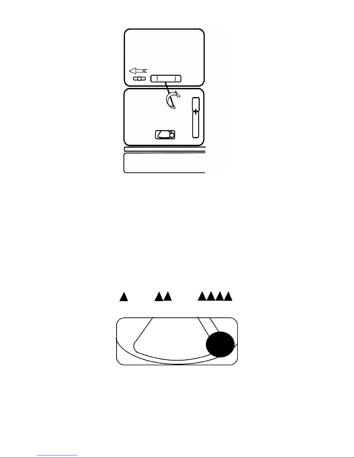
Remove unburned waste rom the upper grate by means o the shovel and the ire rake. Empty
the lower grate into the ash tray by pushing out and turning the grate lever to the right (Figure 3).
Remove the top-hob and sweep the soot rom the dirty internal sur aces, remove the cover in the
rear part o the grate bearing. From there the soot can be moved to the ash tray through a
sweeping hole. Empty the ash tray.
A ter cleaning, restore the appliance to its original state. Take care o the act that packing line is
set correctly as well as the top-hob in its rame.
Appl ance Operat on
Clean ng and
M
a ntenance

TYPE 9101 07/2014 10
Outer surfaces clean ng
Clean the appliance a ter cooling.
• Enamelled sur aces should be cleaned with a damp cloth or sponge, and then polished to
dryness. Never use abrasives which could a ect the enamel sur ace. With higher pollution
you can use detergents.
• It is important to protect the hob rom water to avoid corrosion. Clean it only when it is dry. I
you use a damp cloth with detergent when cleaning the hob, the hob should be dried when
inished. From time to time we recommend greasing the hob with a thin layer o vegetable at.
The appliance cannot be lit: - inspect the lue ways, lue gas duct and chimney
- check the, air rose, ire place door and ash tray
Overheated appliance - put out o service, do not stoke, close the air rose, let ire burn
out
Fire in the chimney - do not use water to extinguish the ire
- close all o the air intakes, cover the chimney i possible
- contact a quali ied chimney sweep service to evaluate the
chimney condition a ter the ire
- contact your supplier.
Do not carry out repairs by yoursel i aults occur during the guarantee period. File a claim in the
shop where the product was bought or in a guarantee repair shop and support it with a duly
completed guarantee card. Guarantee claim requests can be set up only in cases where all
guarantee conditions are met.
Corrugated board, packing paper - recycle
Wooden parts - recycle or re-use
PVC strips, sacks, oils - recycle i available, or dispose o sensibly
The appliance contains valuable materials that can be recycled. Your Local Authority or a licensed
scrap irm can organise this or you.
D sposal of the Packag ng
D sposal
of the Appl ance
after ts Serv ce L fe
Trouble
-
Shoot ng
Cla ms

TYPE 9101 07/2014 11
Based on the design solution and the use to which the appliance will be put, this solid uel
appliance must be installed into an environment which was de ined as an ordinary environment
( or example by ČSN 33 2000-3:1995 – Environment standard o the Czech Republic).
Requirements or combustion air supply will be met i the appliance is installed in a room with a
minimum volume o 20 m3. According to need, the appliance operation or in combination with the
contemporary operation o other heat equipment in the room, additional ventilation may be
necessary. In cases where dangerous situations may arise, such as the temporary ormation o
combustible gases and works which may cause a ire to start (potentially explosive), the appliance
should be put out o service (by closing the combustion chamber door the uel will be allowed to
burn out on the grate). I combustion, venting and heating air control louvers are used, it is
necessary to place them in such a way that clogging cannot occur.
Appl ance connect on to the ch mney
A lue (exhaust) branch is installed to an outlet on the appliance (rear, both sides, and top –
through the hob-top). The installation is carried out in such a way that a ring is applied to the
internal side o the appliance, which connects with the external lue branch, and they are mutually
screwed together moving in the opposite direction.
In case you use a side outlet, it is irst necessary to unscrew the side part, rom which we
dismantle the top cover o the hole, apply the blanking cap to close the rear outlet, replace the
side part and screw it closed.
With the use o the top outlet (through the hob-top) it is necessary to remove the blanking cap and
to attach the lue branch – without the ring, and use the delivered blank cover to close the rear
outlet.
A chimney with a su icient draught is absolutely essential or correct appliance operation. We
recommend the ch mney w th he ght of 5 meters and d ameter of 160 mm. Try to connect the
appliance using the shortest route. Flue gas ducting made o sheet-metal tubes consists o
several sections and i longer than 2,000 mm, shall be irmly anchored. The entire set shall be
mutually, irmly and tightly connected in the draught direction (individual overlaps must be a
minimum o 80 mm). An existing chimney lue shall be provided with an approved metal liner lue
that corresponds to the exhaust lue diameter. The appliance should be installed in such a way
that adequate access can be provided or cleaning o the lue ducting and the chimney.
Connection o the appliance to the chimney should comply with the individual national regulations
at place o installation and use ( or example ČSN 73 4201:2008 Standard o the Czech Republic).
The chimney shall be issued with a certi icate (revision report) given by a respective authority
(chimney sweeping agency). The appliance should be installed in such a way that adequate
access can be provided or cleaning o the lue ducting and the chimney. In assembly, it is
necessary to observe the principles o ire sa ety ( or example according to the ČSN 06 1008:1998
Standard o the Czech Republic). The cooker can be connected to a shared chimney (Fig. 6).
Chimneys and lue ducting to which solid uel are connected shall be swept 6 times a year ( or
example according to the Department o the Interior Czech Decree No. 111/82 Coll.). Routine
operation, especially due to damp uel, soot and tar creates deposits in the chimney. I regular
inspection and chimney cleaning are omitted, the probability o a ire in the chimney increases.
INSTALLATION MANUAL

TYPE 9101 07/2014 12
Safety nstruct ons
The minimum sa e distance rom lammable matters with a combustibility grade o B, C1, C2 is a
minimum 750 mm orward o the appliance and 200 mm to the sides and. For lammable matters
with C3 combustibility grade and/ or with an unproven combustibility grade, the distance should be
doubled. No lammable objects should be laid on the appliance and should be kept at a sa e
distance rom it. When the appliance is situated on a loor made o a lammable material, it should
be set on a ireproo , thermo-insulating plate overlapping its section plan:
- not less than 600 mm at the ront (be ore the stoke hole)
- not less than 300 mm rom the lateral side o the stoke hole.
A protective ba le plate is used in cases where, due to space reasons, the prescribed sa e
distance cannot be kept. The protective ba le plate shall have a constant position between the
appliance and the protected material in a distance o 30 ±5 mm rom the protected material. The
protective ba le plate shall overlap the protected material up to the nearest wall (ceiling) made o
a ireproo material, however not less than 300 mm at the upper side and 150 mm at the lateral
sides. We recommend that your nstaller check th s reduced d mens on w th your local
bu ld ng control department.
Description o materials type or lammable classi ication in cookers manuals (in accordance with
Czech and EU standard No.73 0823):
Flammable level Rat ng Mater als
______________________________________________________________________________
А. Non- lammable asbestos, brick, ceramic wall tile, chamotte,
plaster mixture (without organic enclosure).
В. Uneasy- lammable building wall panels ( or example a
gypsum wallboard), VELOX, IGNOS,
touchstone elt panels, ibreglass panels).
С1. Flammable with di iculty beech wood, HORBEX board,
wood multi-layer board, WERZALIT,
Formica, elt boards.
С2. Moderately lammable pine tree wood, larch wood, spruce wood,
wood chip boards.
С3. Easily lammable sarking elt, cellulose boards, tar panels,
wood-pulp ibre, phellem, polyurethane,
polystyrene, polypropylene, polyethylene.
Warn ng for places where burns can occur:
• hob-top, hob rame
• combustion chamber door

TYPE 9101 07/2014 13
Flue gas duct ng connect on to the ch mney
(valid or Czech Republic)
correct wrong
Figure 6

TYPE 9101 07/2014 14
1. Product on standards
KVS MORAVIA solid uel appliances are produced in accordance ČSN EN12815:2002 Standard
with amended A1:2005, which is valid or the Czech Republic and European Union.
2. Installat on and operat on standards
All the above installation and operation instructions or the appliances primarily comply with the
Czech regulations, and may not comply ully to individual national regulations at place o
installation and use!
The buyer should consult their installer or specialised o icials on all o the local installation and
operation regulations or this appliance or similar appliances!
D mens onal Sketch of the appl ance
Type 9101
(All of d mens ons are n mm)
Important not ce

TYPE 9101 07/2014 15

TYPE 9101 07/2014 16
Producer:
KVS EKODIVIZE, a. s.
Plant Dvorce
Opavská 272
793 68 Dvorce u Bruntálu
CZECH REPUBLIC
Telephone : +420 554 797 111
Fax : +420 554 745 500
E-mail: prodej.dvorce@kvs-ekodivize.cz
www.kvs-ekodivize.cz
Table of contents
Other KVS MORAVIA Cooker manuals
Popular Cooker manuals by other brands

Dometic
Dometic CU333 Installation use and service manual

Bosch
Bosch HCA628.2.U instruction manual

Cannon
Cannon HARROGATE C60DH Use and Installation Instructions

Hotpoint
Hotpoint EG1000EX operating instructions

Range Master
Range Master Professional+ 100 FX User's guide & installation instructions

Range Master
Range Master PROP90EI User's guide & installation instructions