Kyocera C100 User manual

Kyocera C100 Neutralisation unit
Instruction manual | Status - November 2023
SOFTWARE VERSION 3
IMPRINT
Editor
KYOCERA Fineceramics Europe GmbH
Environmental equipment
Steinzeugstraße 92
68229 Mannheim
Germany
Environmental equipment department
Tel: +49 621 40547-300
email: info@kyocera-fineceramics.de
Internet: www.kyocera-fineceramics.de
Authors
Text: Christian Schmitt
Photos: Christian Schmitt
Drawings: Roland Merscher
For more information and contact details for Kyocera Service, please follow the link:
www.kyocera-fineceramics.de
Our product specifications are based on extensive technical development and the results from stringent
tests. We have many years’ experience in different application areas which provides additional security
with regard to the durability of FRIDURIT environmental equipment. However, it is the responsibility of the
user to check our specifications and recommendations and conduct their own tests to confirm that they
are suitable for their intended purpose.
The statutory warranty provisions apply. We also refer to our General Terms and Conditions of Supply
and Payment.
We reserve the right to make technical changes.

Instruction manual | Status - November 2023 Page 2
1. PREFACE .............................................................................................................................................3
2. NOTES ON USING THE INSTRUCTION MANUAL .................................................................................3
ABOUT THIS INSTRUCTION MANUAL .......................................................................................................................... 3
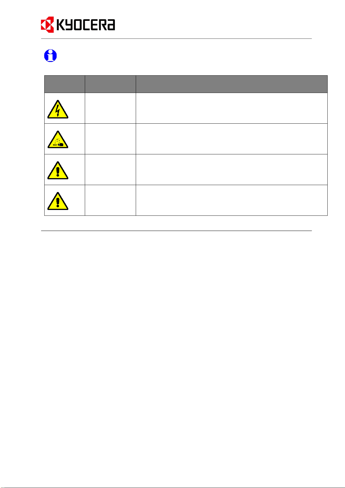
SYMBOLS AND MARKINGS.......................................................................................................................................... 3
3. INTENDED USE .....................................................................................................................................4
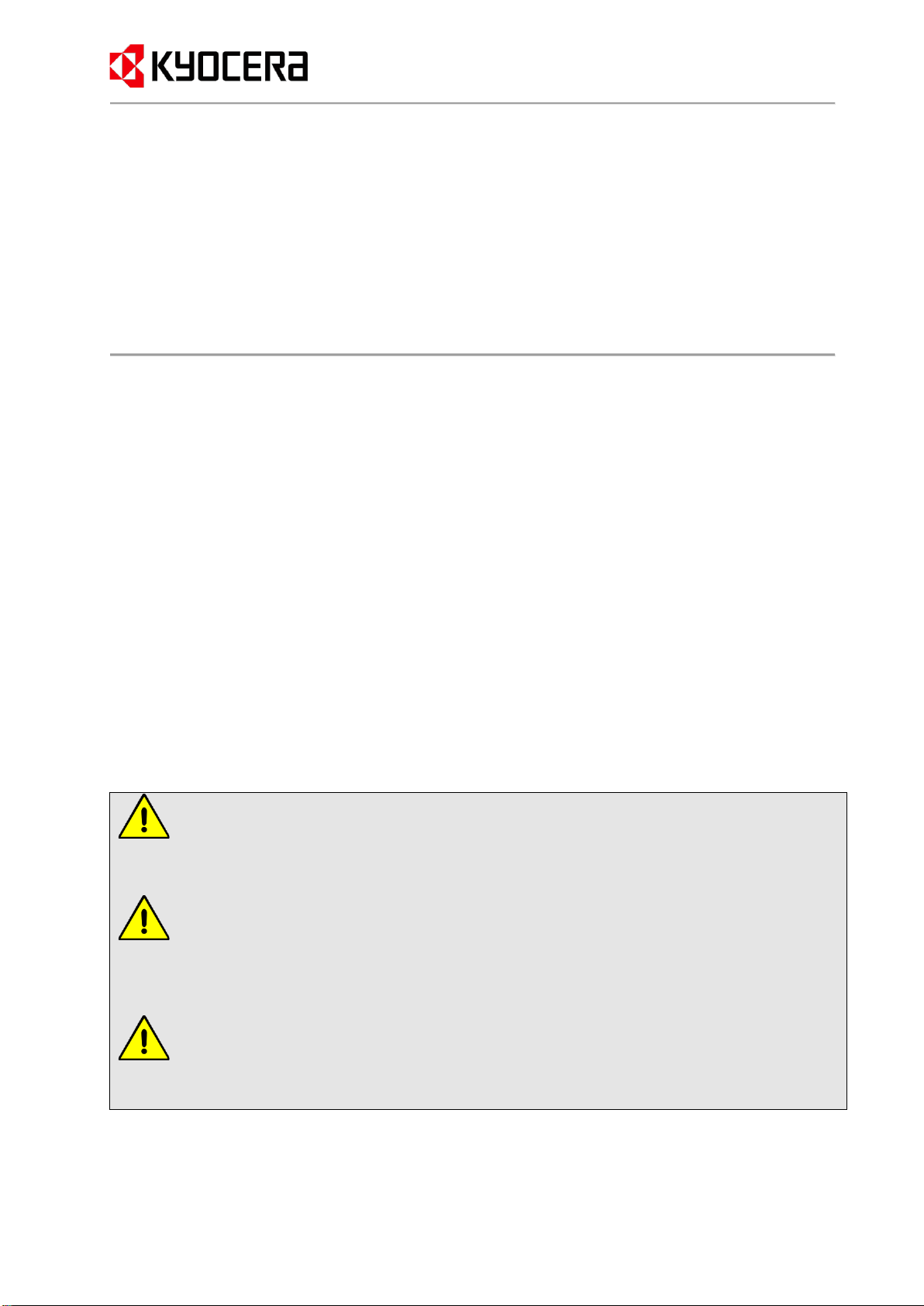
4. GENERAL SAFETY INSTRUCTIONS .......................................................................................................5
PRODUCT SAFETY ...................................................................................................................................................... 5
GENERAL SAFETY INSTRUCTIONS............................................................................................................................... 5
ASSEMBLY AND INSTALLATION ................................................................................................................................. 6
OPERATION................................................................................................................................................................ 6
MAINTENANCE .......................................................................................................................................................... 6
5. SYSTEM PROPERTIES............................................................................................................................7
MATERIAL ................................................................................................................................................................. 7
CONTROL SYSTEM...................................................................................................................................................... 7
TECHNICAL DATA ...................................................................................................................................................... 7
ACCESSORIES............................................................................................................................................................. 7
SCOPE OF SUPPLY....................................................................................................................................................... 8
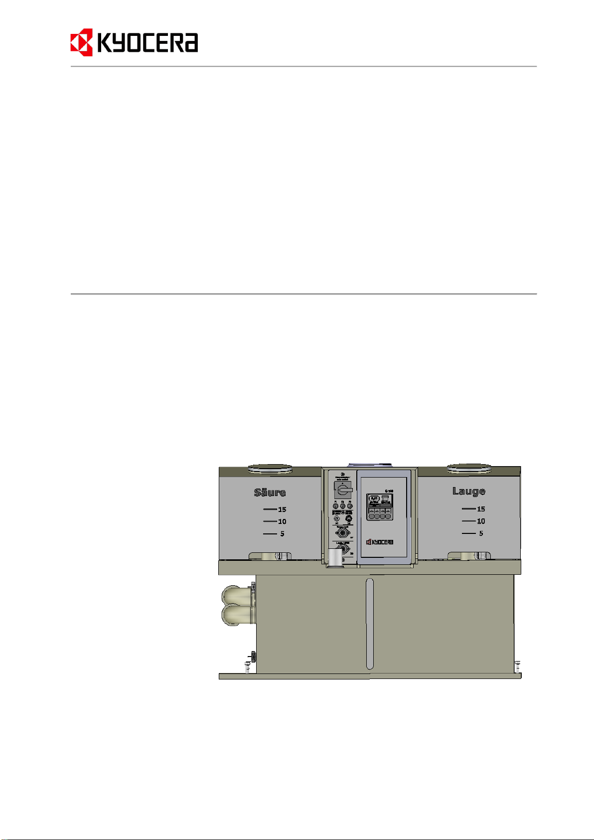
6. PRODUCT DESCRIPTION .....................................................................................................................8
FUNCTION.................................................................................................................................................................. 8
COMPONENTS ............................................................................................................................................................ 8
CONTROL ELEMENTS.................................................................................................................................................. 9
LCD DISPLAY WITH KEYPAD IN AUTOMATIC MODE ................................................................................................... 9
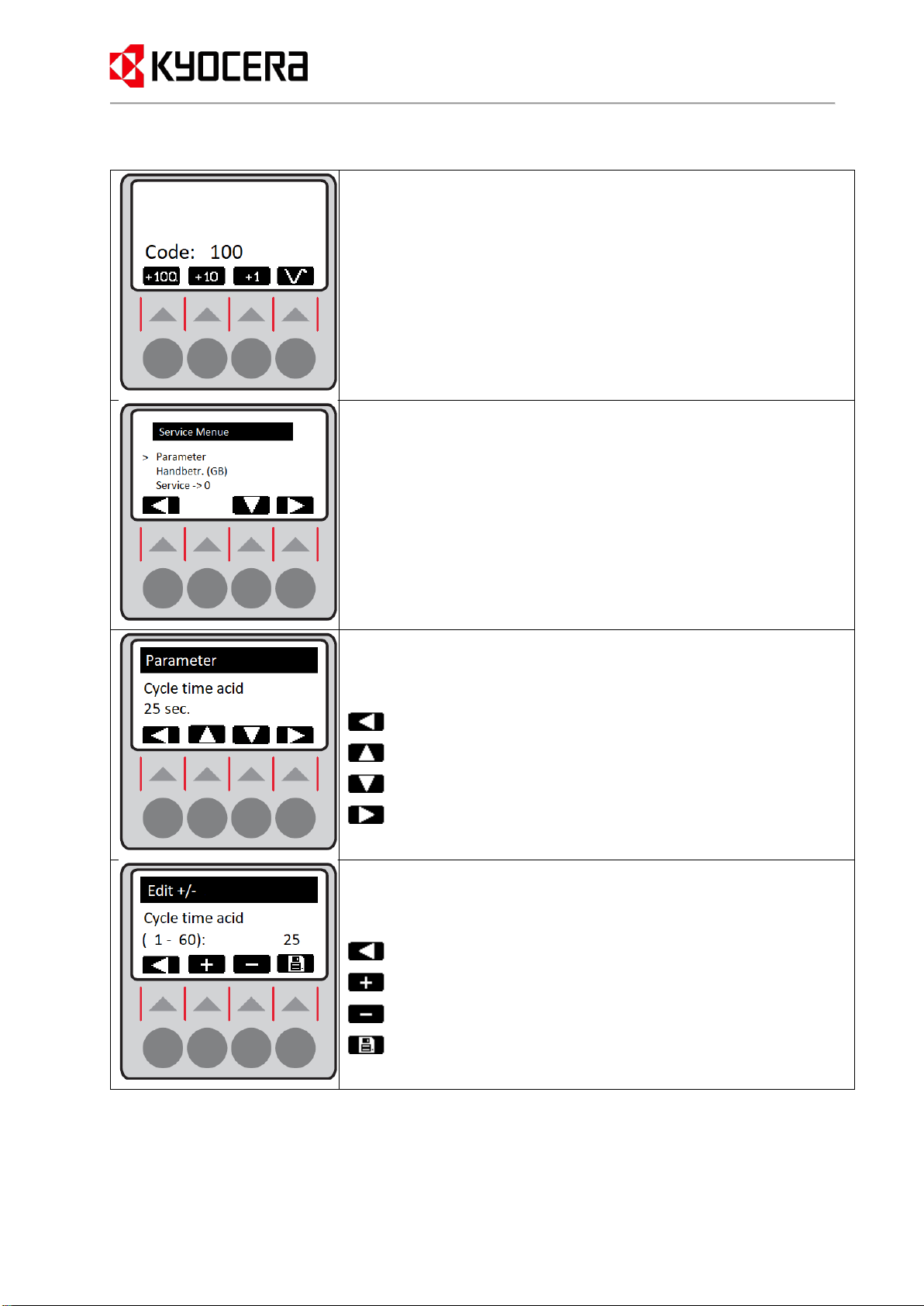
LCD DISPLAY WITH KEYPAD IN SERVICE MODE ....................................................................................................... 10
DEFINITION OF THE NEUTRAL RANGE....................................................................................................................... 11
NEUTRALISATION PROCESS (BATCH OPERATION):.................................................................................................... 11
7. OPERATION.......................................................................................................................................12
COMMISSIONING...................................................................................................................................................... 12
OPERATING INSTRUCTIONS ...................................................................................................................................... 12
CALIBRATION OF THE PHELECTRODE...................................................................................................................... 12
TOPPING UP THE CHEMICALS.................................................................................................................................... 14
8. MALFUNCTIONS AND TROUBLESHOOTING .....................................................................................15
9. SHUT DOWN THE DEVICE ..................................................................................................................16
10. ASSEMBLY .........................................................................................................................................17
QUALITY CONTROL.................................................................................................................................................. 17
UNPACKING ............................................................................................................................................................. 17
CHECKS ON DELIVERY ............................................................................................................................................. 17
ENVIRONMENTAL PROTECTION AND PACKAGING..................................................................................................... 17
11. INSTALLATION ...................................................................................................................................17
PLUMBING CONNECTIONS ........................................................................................................................................ 18

Instruction manual | Status - November 2023 Page 3
ELECTRICAL CONNECTION ....................................................................................................................................... 19
12. INITIAL COMMISSIONING ................................................................................................................20
13. MAINTENANCE AND SERVICING.....................................................................................................21
REGULAR MAINTENANCE......................................................................................................................................... 21
MAINTENANCE SCHEDULE ....................................................................................................................................... 21
14. ENVIRONMENTAL PROTECTION .......................................................................................................21
PACKAGING ............................................................................................................................................................. 21
NOTE ON DISPOSAL .................................................................................................................................................. 22
15. APPENDIX .........................................................................................................................................22
SPARE PARTS ........................................................................................................................................................... 22
CIRCUIT DIAGRAMS.................................................................................................................................................. 22
PARAMETER LIST ..................................................................................................................................................... 23
16. DECLARATION OF CONFORMITY.....................................................................................................24
1. PREFACE
With the Kyocera neutralisation unit, you are making an active contribution to protecting the environment.
Cleaning wastewater contaminated with chemicals directly at the point of origin protects the laboratory
and building structure and minimises risks. This is achieved with a minimum noise level and the smallest
possible installation space.
The Kyocera neutralisation unit helps you to comply with the limit values of municipal waste disposal
companies and their wastewater regulations.
The Kyocera neutralisation unit is characterised by its sophisticated technology, high-quality components
from leading manufacturers, simple and reliable construction and maintenance-friendly design.
2. NOTES ON USING THE INSTRUCTION MANUAL
About this instruction manual
This instruction manual contains both operating and assembly instructions, whereby the operating
instructions are given first because they are expected to be used more frequently. Users of the Kyocera
neutralisation unit should read the instruction manual...:
- Read carefully before use
- Store during the service life of the device
- Make it accessible to staff at all times
If you have any further questions, please do not hesitate to contact Kyocera Environmental Equipment
(see cover page for contact details).
Symbols and markings
The content of the instructions is divided into four text elements: Pure information text, procedural
instructions, notes and safety instructions. You can recognise the corresponding text elements by the
following markings:
Information text: Continuous text without mark-up

Instruction manual | Status - November 2023 Page 4
Notes: Blue information symbol with textual description.
Safety instructions: Yellow Hazard symbols with textual description are highlighted in grey.
Symbol
Signal word
Meaning
Warning!
Indicates a potentially hazardous situation caused by electrical energy.
Failure to observe the warning may result in serious damage to health
and/or property.
Warning!
Refers to a potentially hazardous situation caused by aggressive
chemicals. Failure to observe the warning may result in serious damage
to health and/or property.
Caution!
Indicates a potentially hazardous situation. If not avoided, minor injuries
and damage to property can result.
Attention!
Indicates a potentially harmful situation. If it is not avoided, the device or
objects in the vicinity may be damaged.
3. INTENDED USE
The Kyocera neutralisation unit should only be operated in the intended manner.
It purifies acidic and alkaline wastewater directly at the point of origin in chemical laboratories and similar
applications or as a central neutralisation unit in conjunction with storage tanks and other accessories.
Limit data:
Media temperature at the inlet connection: +10°C to +40°C
Ambient temperature: +10°C to +35°C
Non-intended use:
The Kyocera neutralisation unit is not suitable for treating the following substances:
•Hydrofluoric acid HF (concentration greater than 1 g/l)
•Heavy metals
•Oils and fats
•Sanitary wastewater
•Protein
•Starch
•Emulsions and dispersions
•Paints and varnishes
•Sticky and fibrous substances
•Solids

Instruction manual | Status - November 2023 Page 5
The following events may occur as a result of non-intended use:
•Defect in the pH electrode
•Failure in the pH measurement
•Pumping out non-neutralised wastewater
•Defect in the mix-pump unit
Service work and damage to the unit caused by the aforementioned substances are excluded from the
warranty.
Please discuss your specific application with the manufacturer
(see cover sheet for contact details).
4. GENERAL SAFETY INSTRUCTIONS
This chapter describes the general safety instructions. Please read these carefully. They provide
information on how to avoid damage to property or personal injury. These and other safety instructions
can also be found at the relevant points in the text.
Product safety
KYOCERA Fineceramics Europe GmbH guarantees a high quality standard of the manufactured products
through a certified quality management system (EN ISO 9001). All devices are subjected to a final
inspection before leaving the factory.
The Kyocera neutralisation unit may only be used if it is in perfect technical condition and in accordance
with its intended use, in a safe and hazard-conscious manner and in compliance with the instruction
manual.
Faults and defects in the unit that could impair safety must be rectified immediately.
Only original spare parts from the manufacturer may be used for repairs.
The applicable national, regional and company regulations must be observed, particularly with regard to
explosion protection, safety and accident prevention.
General safety instructions
Attention!
The unit must be installed by trained specialists. You can obtain the addresses of experienced
installers and service partners from the supplier of the unit.
Attention!
Do not feed: Please note that the unit is not suitable for treating hydrofluoric acid HF (concentration greater
than 1 g/l), heavy metals, sanitary wastewater, protein, starch, oils, fats, dispersions, paints, varnishes,
sludge, sticky and fibrous substances and solid impurities (see checklist).
Attention!
Observe the company accident prevention regulations! If in doubt, please contact the responsible
safety officer.

Instruction manual | Status - November 2023 Page 6
Attention!
Risk of contamination! Despite carefulmanufacturing and material selection, leaks may occur in the unit.
In this case, appropriate protective measures (safety tub, floor drain, etc.) should be provided.
Attention!
Ensure adequate ventilation! Ensure that theunit location is adequatelyventilated,especially when filling
the chemical tanks.
Assembly and installation
Attention!
Risk of damage to the device! Assembly and maintenance of the device may only be carried out by
qualified personnel. Damage caused by improper work will invalidate the warranty. The applicable norms
and standards must be observed for all assembly and maintenance work.
Danger!
Electrical energy! Risk of personal injury due to electrical energy. Risk of damage to the device. The
electrical connection of the Kyocera neutralisation unit should be carried out by a qualified electrician.
Damage caused by improper connection voids the warranty.
Warning!
Corrosive chemicals! Risk of chemical burns and damage due to leaks! The overflow shall not be closed
or restricted by a waste trap or a stop valve. Do not damage the seals during assembly.
Operation
Warning!
Corrosive chemicals! Risk of chemical burns or damage to the device! Do not remove any covers from
the device during operation!
Maintenance
Danger!
Electrical energy! Risk of personal injury due to electrical energy! When working on the device, set the
repair switch to "0" to disconnect the control system from the power supply.
Warning!
Corrosive chemicals! Risk of chemical burns due to contact with the neutralisation chemicals! Wear
protective clothing during maintenance work. Please also observe the company safety regulations. Avoid
contact with the wastewater in the unit and in the pipework!

Instruction manual | Status - November 2023 Page 7
5. SYSTEM PROPERTIES
Material
All wetted parts of the Kyocera neutralisation unit are made of chemically resistant plastics. The reaction
tank, the chemical tanks and the wetted parts of the mix-pump unit are made of polypropylene (PP).
Other construction materials include polytetrafluoroethylene (PTFE), polyvinyl chloride (PVC),
fluoropolymer (FPM) and ethylene propylene diene monomer rubber (EPDM).
Control system
The control and monitoring elements required for operation are housed in a compact control housing that
has been integrated into the housing contours. The use of a modern electronic control system ensures
that the Kyocera neutralisation unit functions reliably. Numerous interfaces enable simple and flexible
connection of the control system to other components and on-site equipment.
The optionally available analogue output (receptacle X4) must be ordered separately. Otherwise, the
corresponding receptacle is fitted but not wired.
Technical data
Capacity:
Reaction chamber: approx. 100 litres
Acid/alkali tank: approx. 25 litres
Neutralisation performance:
max. 200 l/h with average pollutant content in the wastewater (acid or
alkali)
pH measurement:
High-resistance voltage measurement, measuring range 0-14 pH,
floating, resolution 0.1 pH
Alarm contact:
Potential-free changeover contact, 250 V AC, 2 A, 200 W
Operator guidance:
Membrane keypad with backlit graphic display 128x64 pixels and 4
operating buttons
Interfaces:
Optional: Analogue interface 0/4 - 20 mA,
serial interface RS-232
Temperature range:
Ambient/media temperature: +5 - +35 °C
Accessories
Note: We also stock suitable accessories for your individual application, such as storage
tanks and neutralisation units for chemically contaminated wastewater, paper and screen
loggers, a complete pH follow-up check, etc. If required, please contact our application
technology department.
The following components can be supplied for customised applications:
•DN40 inlet installation set made of PVC-U, consisting of manual ball valve, soil trap and 230V
50Hz motor ball valve
•Kyocera storage containers with capacities from 300 to 2000 litres, each with electronic visual
and audible alarm for maximum fill level
•Independent monitoring device for the pH value in the wastewater downstream of the
neutralisation unit with recording by a paperless logger

Instruction manual | Status - November 2023 Page 8
•Chemical-resistant pump unit with plastic feed pump and electrical control system
All components are coordinated and optimised for easy installation. Please discuss your individual
application with the Kyocera environmental equipment staff.
Scope of supply
The Kyocera neutralisation unit is supplied as a complete and ready-to-use unit. The following parts are
included in the scope of supply:
Kyocera C100 neutralisation unit with integrated chemical tanks, mix-pump unit and integrated control
system, pre-assembled ready for operation.
Accessory pack with accessories (mating connector for plug-in connectors, fastening parts).
Technical documentation (operating and assembly instructions for neutralisation unit and accessories,
circuit diagrams, etc.).
6. PRODUCT DESCRIPTION
Function
The Kyocera C100 neutralisation unit is used for the simple and reliable neutralisation of laboratory
wastewater directly at the point of origin.
It can be operated in conjunction with a Kyocera fume scrubber to neutralise the scrubbing liquid or as a
free-standing unit. Various additional components, such as a storage tank, chemical-resistant pump unit,
inlet installation set, etc., enable customised adaptation to different tasks.
Components
1. Reaction vessel
2. Chemical container for
acid
3. Chemical container for
alkali
4. Control system with pH
meter, keypad and
graphic display
5. Mix-pump system
(behind the control
system)
6. Inlet connection
7. Overflow connection

Instruction manual | Status - November 2023 Page 9
Control elements
1. Repair switch for disconnecting the unit from
the power supply for servicing
2. Miniature fuses F1 to F3 (see chapter
Troubleshooting)
3. Input receptacle for
pH electrode connection cable
4. Plug-in connection for analogue and digital
interface (option 1)
5. Receptacle for acid solenoid valve plug
(orange cable colour)
6. Receptacle for alkali solenoid valve plug
(grey cable colour)
7. Display for unit status and operator guidance
8. Keypad for operation
LCD display with keypad in automatic mode
Top left:
Symbolic representation of the unit function.
Top right:
Current pH value in the reaction tank.
Centre:
Text description of the unit function in keywords.
Below:
Dynamic assignment of button functions.
Symbol
Description
Manual start of the neutralisation process, regardless of the fill level in
the reaction tank, in the "Fill tank" state.
Activates the backlight of the LCD display, otherwise no function is
executed.
Activates the service menu to change parameters or perform service
functions (e.g.: Set language). The menu is password-protected
against unauthorised access.
Activates the calibration menu for calibrating the pH probe. The step-
by-step calibration is described in detail in the operation chapter.

Instruction manual | Status - November 2023 Page 10
LCD display with keypad in service mode
The service code is set by pressing the corresponding buttons and can
be confirmed with the right button.
If an incorrect code is entered, the control system returns to automatic
mode.
To reset the code and restart the entry, press the left button until a code
above 1000 is reached, then the initial value of 100 is set again.
The service menu offers the following options:
Parameters: Display and change parameters such as mixing time,
control parameters, etc.
Manual operation: Performing manual functions such as pumping out,
controlling valves.
Service -> 0: Resets the maintenance message.
Display parameters:
Centre line: Name of the parameter
Bottom line: Set value of the parameter
Cancel process
Display previous parameter
Show next parameter
Change parameters
Change (edit) parameters:
Centre line: Name of the parameter
Bottom line: Setting range and setting value
Cancel process
Increase parameter value
Decrease parameter value
Save parameters

Instruction manual | Status - November 2023 Page 11
Attention!
Functions activated in manual mode as described below can lead to uncontrolled dosing of
chemicals or wastewater contaminated with chemicals entering the sewer system.
This is the sole responsibility of the operator!
Manual operation (manual function):
> (Cursor) marks the current function
Cancel process
Select previous function
Select next function
Activate function
Manual operation (manual function):
The activated function is displayed inversely
Cancel process
Select previous function
Select next function
Deactivate function
Note: Changing the function deactivates all previous activations!
Definition of the neutral range
Neutralisation process (batch operation):
Step
Description
Symbol in the display
1
The discharged wastewater is channelled into the reaction tank
2
Once the maximum fill level has been reached, the container contents
are first mixed.
3
After premixing the contents of the container, acid or alkali is dosed
from the reservoir tanks until the pH value in the reaction tank is
within the legally permitted limits.
(dosing valve open)
(dosing valve closed)

Instruction manual | Status - November 2023 Page 12
Step
Description
Symbol in the display
4
The pH value in the reaction tank must remain stable in the neutral
range during the monitoring time, otherwise dosing will start again.
5
After a preset monitoring time, the motor stops to change the
direction of rotation
6
The contents of the tank are pumped into the wastewater pipe.
This fully automatic batch operation is controlled by a special measuring and control system with a RISC
microcontroller.
7. OPERATION
Commissioning
Switch on the unit with the main switch
Inlet ball valve opens (if present)
Operating instructions
In normal operation, all control functions are performed automatically. Please refer to the maintenance
schedule for the regular maintenance activities to be carried out by the operating personnel.
A regular check of the pH electrode ensures the functionality of the unit and thus compliance with legal
requirements.
Attention! Risk of non-compliance with limit values. Regular recalibration ensures the functionality of the
unit and thus compliance with the required limit values.
Calibration of the pH electrode
Before calibration
Please note the following points in advance:
•Before the first calibration, a pH electrode must first be placed in normal drinking water (not
demineralised water!) for several hours in order to provide accurate measurement data.
•Also use normal drinking water to rinse the electrode.
•Please observe the electrode manufacturer's instructions on the supplementary sheet enclosed
with each probe. If the supplementary sheet is no longer available, you can of course obtain a
replacement from Kyocera.
•The glass membrane of the electrode is very sensitive to mechanical influences. Please proceed
with appropriate caution during the calibration process.

Instruction manual | Status - November 2023 Page 13
Disassembly and assembly of the pH electrode
Disassembly
Assembly
Step
Description
Illustration
Step
Description
Illustration
1
Carefully pull the
protective tube and
bracket apart.
1
Unscrew the
electrode plug.
2
Unscrew the electrode
plug.
2
Carefully insert the
electrode into the
holder and screw it
hand-tight into the
thread.
3
Unscrew the electrode
from the thread and
carefully pull it upwards
out of the holder.
3
Screw the electrode
plug back on.
4
Screw the electrode
plug back on.
4
Plug the protective
tube and bracket
together.

Instruction manual | Status - November 2023 Page 14
Perform calibration
Step
Description
Symbol in the
display
1
Pressing the button in automatic mode sets the control system
to calibration mode and stops automatic mode
*** Calibration ***
2
Remove the pH electrode from the fitting (see section "Disassembly")
and clean carefully with water. When cleaning is complete, press
to continue.
3
Immerse the pH electrode in buffer 1 and wait for a stable measured
value (pH value in the top line), accept the measured value with the
button or set the correct buffer value with the or
buttons.
4
Remove the pH electrode from buffer 1 and clean it carefully with
water. When cleaning is complete, press to continue.
5
Immerse the pH electrode in buffer 2 and wait for a stable measured
value (pH value in the top line), accept the measured value with the
button or set the correct buffer value with the or
buttons.
6
Calibration log is displayed. This calibration data is permanently
saved in the control system as soon as the button is pressed.
Calibration is now complete and the control system returns to
automatic mode.
Information in the calibration log
The values in the top two lines indicate which buffer was used for calibration and which internal values
were measured. These values can be helpful for troubleshooting, but are not relevant for calibration.
The lower lines indicate the zero point and the slope of the calibration. The further the zero-point deviates
from the ideal value (0 mV), the greater the shift in the zero point. This is a quality criterion, a value
greater than +/- 50 mV is an indication of "poisoning" of the electrode, the electrode should be replaced
as soon as possible.
The steepness of the electrode serves as a further quality criterion. This is the ratio of the actual
measured value to the theoretical value (-59 mV/pH). A slope of less than 80% is also an indication that
the electrode will soon fail, so it should be replaced as a precaution.
Note: If the slope is below 80%, the electrode no longer measures reliably and should be
replaced immediately!
Notes:
If a fault occurs during calibration, this is shown on the display at the end of the calibration process.
Please repeat the calibration.
Topping up the chemicals
The chemical tanks of the neutralisation unit should be checked from time to time by checking the level
on the sight glass. Refilling is necessary if the fill level falls significantly below 5 litres.
Please proceed as follows:
•Switch off the unit
•Unscrew and remove the plug from the empty container

Instruction manual | Status - November 2023 Page 15
Attention: It is essential to wear protective goggles, gloves and
protective clothing when carrying out the following steps, as accidents
involving acid and alkali can result in severe burns.
Filling the acid and alkali tank
•Pull the container out forwards until it locks in place or
remove the container from the holder (sketch) and place it
on a stable surface
•Unscrew the cover
•Fill acid and alkali tank with:
Hydrochloric acid HCl or caustic soda NaOH,
maximum concentration 20%, technical quality sufficient!
Never mix acid and alkali, as this will lead to a violent reaction between the chemicals and
generate a lot of heat!
Risk of tipping! Do not place the chemical canister on the tank when filling.
Please adhere to the specified concentration. At higher concentrations, the service life of the
seals is considerably reduced.
After filling
•Screw the cover on
•Remove any contamination (splashes) immediately.
•Put the tank back into the holder and make sure it is seated correctly.
•Insert the plug into the control system and lock it.
•Switch the unit on again.
Tip: When filling the chemicals for the first time, the tanks should be filled no more than half full, as
they must be removed again by the service department during commissioning activities or in the
event of a leak in the chemical container (e.g.: damage during transport).
8. MALFUNCTIONS AND TROUBLESHOOTING
Follow the list and check the individual questions. If the answer is "Yes", go to the next point; if the
answer is "No", read the instructions in the right-hand column.
Attention: Before working on the electrical parts of the neutralisation unit, disconnect the plug in
the supply line. Disregard can result in considerable damage to property and personal injury!!!
Fault:
Check
Action if "No"
Unit not working
Repair switch in position "I"?
Switch on the repair switch
Is the supply plug inserted
correctly?
Insert supply plug correctly
Voltage at the mains socket?
Have the cause determined by an
electrician
Fault in electrical circuit, request
service!
1.
2.

Instruction manual | Status - November 2023 Page 16
Unit does not fill
Ball valve in supply line open
(knob parallel to pipe?)
Open ball valve
Inlet strainer still clean?
Close the ball valve,
unscrew the strainer tube holder,
clean the strainer insert,
screw in the strainer tube holder,
open the ball valve again
Is X11 plug on the rear of the
control system plugged in?
Insert plug firmly and lock
clockwise
Request service!
"ALARM PH MEASUREMENT"
message
Are the cable connections of the
pH electrode still OK?
Screw or lock the cable tightly.
pH electrode still OK (visual
check)?
Order a new pH electrode or
request service
Probe recalibrated in accordance
with the maintenance schedule?
Recalibrate electrode
Order service!
Unit has been running for a long
time without any change in the pH
value
Are sufficient neutralisation
chemicals still available?
Refill container
Are the pH electrode and chemical
tank cables plugged in?
Plug the cable into receptacle X5
on the control system and lock it in
place
pH electrode still OK (visual
check)?
Order a new pH electrode or
request service
Probe recalibrated in accordance
with the maintenance schedule?
Recalibrate electrode
Order service!
Storage tank control system
issues alarm
Tank full and neutralisation unit
neutralising?
See point "Unit does not fill"
Stop operation and wait until the
alarm light goes out again (switch
off the horn with the
"Acknowledge" button)
The following cases require a service call without prior inspection:
•Message "Motor fault" appears on the display
•Control system stops during the mixing process, despite display of pH value > 6.5 and < 9.0
•Unit does not mix (lack of motor noise) or does not pump out
•Unit overflows
9. SHUT DOWN THE DEVICE
In automatic mode, press the button to close the motor ball valve
After switching off the motor ball valve, turn the repair switch on the control system to the "0" position

Instruction manual | Status - November 2023 Page 17
10.ASSEMBLY
Quality control
Kyocera laboratory equipment has been used for several years to protect the environment and building
structures. Strict quality control of every device delivered ensures that our products only leave our
premises in perfect condition.
Unpacking
To prevent damage to the device, transport and removal of the packaging as well as assembly should be
carried out with appropriate care.
We recommend that you observe the following points:
Secure the device against knocks or falling during transport.
Particular care must be taken when handling pointed or sharp objects due to the housing material.
Do not use any aggressive or abrasive cleaning agents to clean the device.
Important: We strongly recommend wearing safety goggles when removing the transport straps to
protect against eye injuries
Checks on delivery
We recommend a visual inspection of the packaging for external damage as soon as the neutralisation
unit is delivered. The device should be unpacked and visually inspected as soon as possible after
delivery. In addition to checking for external defects, the scope of supply must also be checked. If a
defect is discovered, a written complaint must be submitted to us within 5 working days of delivery, stating
the order number and the reason for the complaint.
Environmental protection and packaging
The packaging required for the safe transport of our environmental equipment has already been reduced
to a minimum. We recommend recycling the materials used as follows:
Packaging cardboard is fed into the recycling cycle as a valuable raw material.
The packaging film is made of polyethylene (PE) and can likewise be recycled.
For stability reasons, the tensioning straps are made of fibreglass-reinforced plastic and are therefore
residual waste.
For the disposal of wooden pallets, please contact the municipal waste disposal companies.
11. INSTALLATION
The Kyocera C100 neutralisation unit can be installed in laboratory furniture or operated free-standing.
In general, however, the following points should be taken into account during planning:
•The unit requires a minimum substructure height of 64 cm, as otherwise it is not possible to
remove or pull out the chemical containers for filling.
•In order for the Kyocera neutralisation unit to function properly, the local conditions must ensure
that the device is installed horizontally. Installation on the floor is best, as the unit can be
precisely aligned using the 3 levelling screws, thus ensuring safe operation.
•When installing on a frame, make sure that the support area is not too small so that the contact
pressure does not lead to deformation of the plastic housing due to the high weight when filled.

Instruction manual | Status - November 2023 Page 18
•The nature of the installation site should take into account that carelessness when handling the
chemicals or leaks at the connections can lead to contamination in the installation area. Ideally, it
should be installed in a tiled tray that is equipped with a floor drain to remove impurities.
•The drain into which the neutralised wastewater is to be pumped shall not be higher than one
metre from the lower edge of the unit.
•The unit requires a connection for the emergency overflow, which may be positioned a maximum
of 20 cm above the lower edge of the neutralisation unit in order to ensure a sufficient gradient to
the sewer.
•The installation site must be easily accessible for the service technician and must provide
sufficient space for carrying out routine and service work.
•The venting of the reaction tank must be connected to a continuous extraction system so that no
aggressive vapours and gases can escape from the system.
•The room temperature at the installation site must not fall below +5°C in order to ensure reliable
operation of the control system and to prevent the unit from freezing.
•A wastewater connection (min. DN 50) must be available directly at the installation location of the
unit; if the unit is designed with a storage tank, an overflow connection (min. DN 100) must also
be available.
Plumbing connections
The inlet connection and the overflow connection of the neutralisation unit are designed ex works
with a threaded socket R 1½".”This enables a universal connection with all common materials used in
installation technology.
Important: The overflow connection must be routed into the wastewater pipe via the shortest
route and must not be prevented from functioning properly as an emergency overflow by a
reducer, a waste trap, or a stop device
Inlet, overflow, venting of reaction tank;
Mix-pump unit, chemical tank
Figure 2.3: Plumbing connections
Figure 2.4: Pump-out connection
To vent the unit, a connection with an internal thread size R3/4" ”is provided, located under the unit's’acid
tank. The connection should be connected to an existing ventilation pipe or routed to the outside with a
pipe or hose connection via a continuous extraction system.
Note: To ensure that the unit functions properly, we strongly recommend that the ventilation
system is connected correctly . In special cases, considerable material damage may
otherwise occur due to acid vapours or a malfunction of the overflow.

Instruction manual | Status - November 2023 Page 19
The pump-out connection of the neutralisation unit is located directly behind the motor of the mix-pump
unit. A DN15 hose nozzle was provided for the connection so that a simple connection to the existing
wastewater pipe is possible.
The following points must be observed when installing the lines.
•The pump connection must be routed into the wastewater pipe without a stop device.
Components such as syphons are not necessary due to the design of the unit and lead to a
reduction in the flow rate or, in extreme cases, to faults in the operation of the unit.
•The maximum pump-out height is 1 m from the lower edge of the neutralisation unit. The
maximum flow rate is 10 l/min. For higher pumping capacities, please contact our application
technology department.
•In the case of wastewater pipes that are laid below the unit level, the flow of the wastewater must
be interrupted (e.g.: by a higher funnel), as otherwise the suction effect could cause
unneutralised wastewater to enter the sewer system.
•Due to the corrosive properties of the medium to be neutralised, no metallic materials may be
used for parts in contact with the medium.
•Please note that devices such as fume scrubbers, which discharge their wastewater into the
neutralisation unit, have smaller drain cross-sections. In this case, a transition to the larger inlet
cross-section of the neutralisation unit must be made.
Electrical connection
The mains connection of the Kyocera neutralisation unit is equipped with a plug-in connection to ensure
reliable disconnection from the mains and easy replacement of the complete control system for servicing.
The neutral conductor must always be connected, as otherwise malfunctions or the destruction of
individual components may occur.
Ensure that the supply line fuses are clearly labelled and clearly laid out.
Arrangement of the connections on the rear of the control system and their function:
X3: Connection to the motor mix-pump unit
X8: Bottom float switch (minimum fill level)
X9: Top float switch (maximum fill level)
X10: Plug-in connection for connection line, for interlocking with Kyocera fume scrubber and
neutralisation unit
X11: Plug-in connection for connecting motor ball valve or storage tank
X12: Plug-in connection for potential-free fault signalling
Please refer to the enclosed wiring diagrams for the wire allocation on the individual connectors
Important: The electrical connection of the neutralisation unit should be carried out by a qualified
electrician. Damage caused by improper connection is excluded from the warranty!
The applicable standards must always be observed and applied!
Depending on the version and application of the neutralisation unit, the required connection cables are
not included in the scope of supply, as different cable versions and cable lengths are required depending
on the local conditions. These cables should have a minimum cross-section of 1 mm² and a chemical-
resistant sheath (e.g.: PVC). The protective earth conductor (PE) must be included and connected in
every cable.

Instruction manual | Status - November 2023 Page 20
Figure 3.2: Motor ball valve connection
Further information on the electrical design can be found in the enclosed wiring diagrams.
12. INITIAL COMMISSIONING
The initial commissioning of the device should be carried out by a trained and experienced technician
from a Kyocera service partner, as parts of the unit may be damaged or destroyed if faults occur in the
plumbing or electrical installation. In the event of unauthorised commissioning, Kyocera shall only be
liable for faults that are demonstrably attributable to material or assembly errors at the factory.
Initial commissioning can only take place after the Kyocera neutralisation unit and the associated
components have been fully assembled. The installation site must be freely accessible and any materials
required, such as ladders, tools, etc., should be available. Please also note the information on the order
confirmation. The Kyocera service partner will check all the necessary requirements before
commissioning.
Commissioning includes the following activities:
•Checking the installation and functional testing of the unit with the additional components
supplied
•Instruction of the operating personnel
•Test run in the presence of the operator and operating personnel
•Answering questions
Note: The Kyocera service partner will only commission the Kyocera neutralisation unit and the
parts supplied by Kyocera. However, it is advisable to set up the components associated with the
neutralisation unit on the same day so that the interaction of the individual parts can also be
tested. In any case, the Kyocera service partner will endeavour to take desired dates into account
as far as possible.
Please contact the supplier of the unit or Kyocera directly to request the Kyocera service partner.
It is also possible to contact the responsible Kyocera service partners directly. More information
on the Internet at www.kyocera-fineceramis.de
Table of contents