KYOWA MRS-10A User manual

IM-A1174C Jan. 2019
INSTRUCTION MANUAL
MRS-10A
Digital Telemeter
Control Software
Thank you for purchasing KYOWA’s product MRS-10A Control Software.
Read this Instruction Manual carefully in order to make full use of the high
performance capabilities of the product.
Do not use the product in methods other than described in this Manual.
Generally, company names and trade names described in this Instruction Manual are trademarks or registered
trademarks of the companies.
This Instruction Manual may not be copied or reproduced, in whole or part, without consent of KYOWA.
Copyright © Kyowa Electronic Instruments Co., Ltd. All rights reserved.
The contents of the Instruction Manual are subjected to change without prior notice.
We assume no responsibility whatever for any damage resulting from the use of this product.

1
CONTENTS
CONTENTS ····················································································· 1
NOTATIONS USED IN THE INSTRUCTION MANUAL ················································· 2
1.OUTLINE OF PRODUCT········································································· 3
2. SETUP························································································ 4
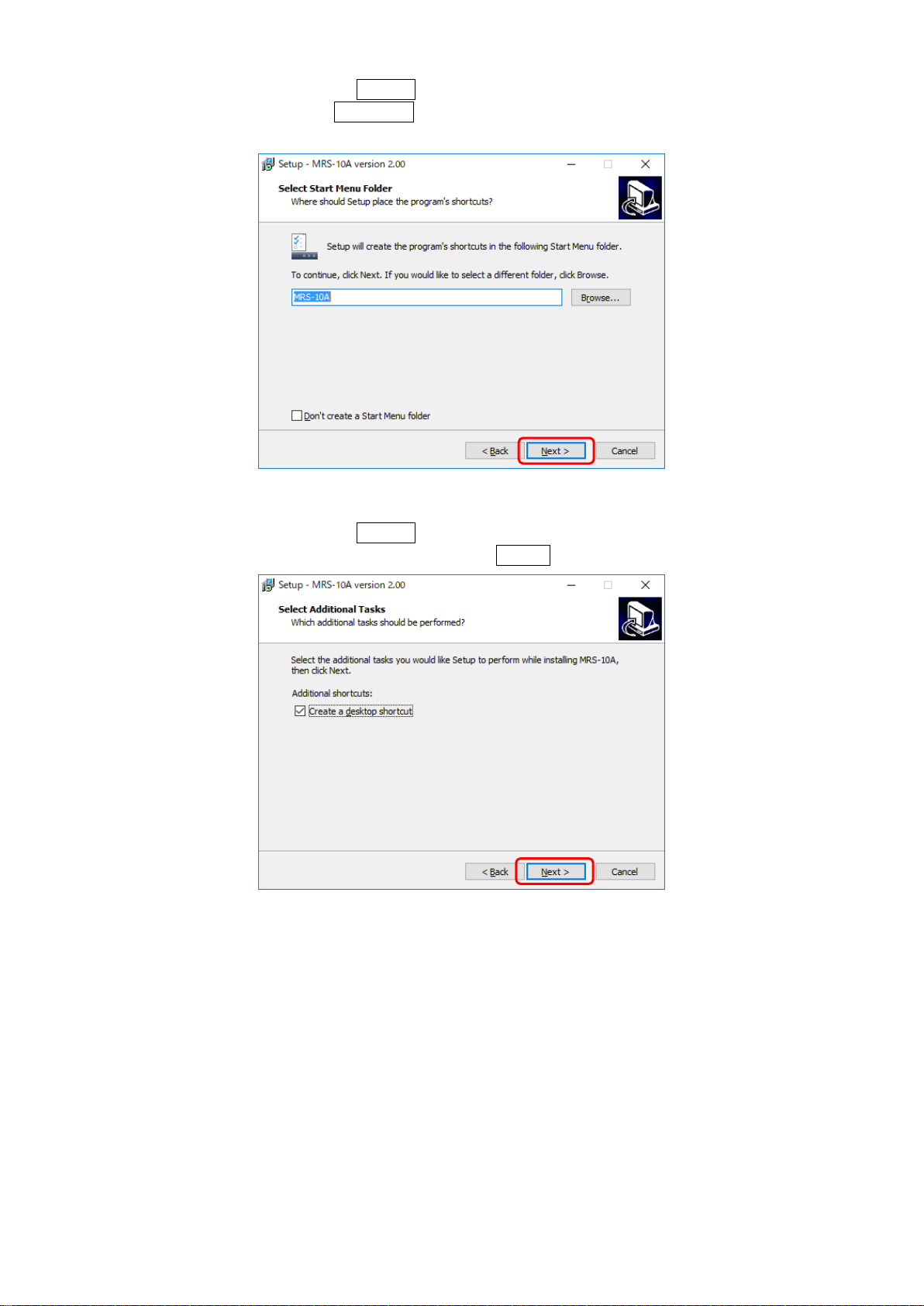
2-1. INSTALLATION ··········································································· 4
2-2. UNINSTALLATION········································································· 9
3. OPERATIONS················································································· 11
3-1. Operation flow ············································································· 11
3-2. Startup procedure··········································································· 12
3-3. Start ····················································································· 12
3-4. [Pairing settings] ··········································································· 18
3-5. [Transmitter settings] ········································································ 22
3-6. [Frequency channel settings] ·································································· 25
3-6-1. Confirm RSSI ·········································································· 26
3-6-2. Change Frequency CH ··································································· 27
3-7. [Sleep settings]············································································· 28
3-7-1. Sleep ················································································· 28
3-7-2. Tx OFF ··············································································· 29
3-8. [Measurement] ············································································· 30
3-8-1. Balance ··············································································· 32
3-8-2. Check ················································································ 33
3-8-3. Communication Error Handling ···························································· 33
3-8-4. RSSI ················································································· 34
3-9. EXIT····················································································· 35
4. The installation of USB device driver ······························································· 36
5.SPECIFICATIONS·············································································· 39

2
Reference items required when handling the product.
Essential precautions required when handling the product.
NOTATIONS USED IN THE INSTRUCTION MANUAL
Certain notations are used as necessary to attract your attention to information that requires special care when handing
the product, and to information provided for reference purposes.
Examples of Notations
IMPORTANT PRECAUTIONS WHEN USING MRS-10A
⚫When any of the following states are enabled on your computer, this software may not function properly:
・Screensaver is scheduled to be activated.
・Energy-saving features such as system standby are activated.
・Software applications such as anti-virus programs are scheduled to be activated.
・Computer is receiving access from the network
or the computer is accessing the network.
⚫About window font size
Select the font size Normal (small).
・Windows 7
Right-click the desktop, and then click “Personalize”from the pop-up menu.
In [Display] window, select “Smaller - 100% (default)”and then click Apply.
・Windows 8 and 8.1
Right-click the desktop, and then click “Personalize”from the pop-up menu.
In [Display] window, select “Smaller”and then click Apply.
・Windows 10
Right-click the desktop, and then click [Display settings] from the pop-up menu.
Move the slider on "Change the size of text apps and other items" to 100% (Recommended).
NOTE
MEMO

3
Some combinations cannot be used depending on the MRS-10Asoftware Ver. and Transmitter and
Receiver Firmware Ver.
Please refer to the following table during use.
〇: usable ×: not usable
MRS-10A
Ver.1.00
Ver.2.00
MRS-111A/-E
Ver.1.00
Ver.2.00
Ver.1.00
Ver.2.00
MRS-101A-S/SE
Ver.1.00
〇
×
〇
〇
Ver.2.00
×
×
〇
〇
MRS-101A-V
Ver.2.00
×
×
〇
〇
If already using MRS-10AVer.1.00, uninstall Ver.1.00, upgrade to Ver.2.00, and then respecify the
Transmitter and Receiver [Pairing settings].
The latest version of MRS-10A can be downloaded from our company’s website.
The Transmitter and Receiver Firmware Ver. can be confirmed from MRS-10A.
The Receiver Firmware Ver. can be confirmed from Receiver information displayed on the [Connect]
tab, and the Transmitter Firmware Ver. can be confirmed from Transmitter information displayed on
the [Transmitter settings] tab.
The MRS-10Asoftware Ver. is displayed on the toolbar.
1.OUTLINE OF PRODUCT
MRS-10A (hereinafter referred to as the Control Software) is software designed to configure and operate the
MRS-111A/-E (hereinafter referred to as the Receiver) and the MRS-101A-S/SE/V (hereinafter referred to as the
Transmitter.)
This manual describes ways for setting and operating the Control Software.
In the following pages, Windows 10 is used to explain the procedure.
NOTE
MEMO
MEMO

4
2. SETUP
2-1. INSTALLATION
Install the Control Software.
When installing updates, follow “2-2. Uninstall” to remove the old version before installing the update.
(1)Select MRS-10A_v*.**.exe in the CD-ROM included, “right-click”, and then select “Run as administrator”.
(2) When the User Account Control pop-up is displayed, click Yes to continue.
(3) Select the display language (English) and then click OK .
(4) Click Next>

5
(5) License Agreement is displayed. Read and verify what it says.
To agree with the conditions, select "I accept the agreement", and then click Next> .
If you select "I do not accept the agreement", you cannot proceed.
(6) Specify the installation directory.
When you verify the installation directory, click Next > .
To select another folder, click Browse... and specify the desired installation directory.
If a folder with the same name already exists, the installation directory confirmation prompt is displayed.
Confirm that the directory is correct and click Yes .

6
(7) Create a program icon.
Once details are confirmed, click Next > .
To select another folder, click Browse... and specify the desired installation directory.
If you do not wish to create a Start Menu folder, check "Don’t create a Start Menu folder".
(8) Create a desktop icon.
Once details are confirmed, click Next > .
If you do not wish to create one, untick, and then click Next> .

7
(9) Confirmation of installation setting is displayed.
When you click Install , the installation starts.
To confirm or change settings, click <Back .
(10) The following window is displayed during the installation.

8
(11) Installation is complete.
Click Finish to close the Setup.
After clicking Finish, the Control Software starts automatically.
If you do not wish to start the Control Software, untick Launch MRS-10A, and then click Finish .
(12) When you select “Create a desktop icon”, an icon is created on the desktop.

9
2-2. UNINSTALLATION
When you perform an uninstallation, the Control Software functions are uninstalled.
(1) From the Control Panel, select “Uninstall a program”.
(2) From the list of programs displayed, select “MRS-10A”and then click Uninstall .
(3) A confirmation pop-up is displayed. Click Yes to start uninstallation.

10
(4) The following window is displayed during the uninstallation.
(5) Once the uninstallation is complete, the following window is displayed.
Click OK and complete the operation.

11
If using the software for the first time, the pair is unknown, or pairing has not been performed, the
popup window below is displayed upon attempting to move to a different tab, preventing you from
doing so.
Click Retry , and then specify the [Pairing setings].
3. OPERATIONS
3-1. Operation flow
Turn the transmitter on.
Turn the receiver on using the
"POWER" switch.
Start up MRS-10A
Connect
[Connect]
・If using for the first time
・If the pair is unknown or there is no pair
Move to a tab
Move to a tab
Pair unknown,
not paired
[Transmitter settings]
[Frequency channel settings]
[Sleep settings]
[Measurement]
[Pairing settings]
Specify pair
settings
Each operation
MRS-10A operation flow
* It is necessary to specify the [Pairing settings] for the Transmitter and Receiver.
NOTE

12
This device uses the 2.4GHz frequency band, which is the same as a wireless LAN, Bluetooth, and
microwave ovens.
Devices using a wireless LAN may create radio interference that could cause communication errors on
this device.
Ensure such devices are not located close by while this device is in operation.
Also, any wireless LAN and Bluetooth features on the computer being used may generate radio
interference. When using a computer to operate this device, ensure that the built-in wireless LAN and
Bluetooth features of the computer are turned off.
The Transmitter mode after turning on the power differs depending on the Transmitter Firmware Ver.
・For Firmware Ver.2.00 or later, it is the Measuring Mode.
・For Firmware Ver.1.00, it is the Command Mode.
3-2. Startup procedure
After turning on the Transmitter, turn on the Receiver.
3-3. Start
(1) Connect the Receiver to a USB port of a computer on which the Control Software has been installed, and then, to
start up, double-click the Control Software icon.
NOTE
MEMO

13
(2) The [Connect] window is displayed, as is the COM port to which the Receiver is connected.
The [Connect] window is displayed.
1) COM: Displays the list of COM ports on the computer.
2) Connect/Disconnect: Connects/disconnects the Receiver to/from the selected COM port.
Before turning off the power of the Receiver, ensure the disconnect procedure is
performed.
When multiple COM ports are detected
Normally, the COM port to which the Receiver is connected is displayed, but multiple COM ports are displayed
in some cases.
In such cases, select the COM port to which the Receiver is connected, and then click Connect .
1)
2)
Multiple
COM ports
Select the COM port
to which the
Receiver is connected.
Click Connect.

14
From the Device Manager, open “Ports (COM & LPT)”, and then confirm the connected port.
If COM port field is blank
This could be due to the following reasons:
a) The Receiver was turned on after starting up the Control Software.
b) Receiver power is not turned on.
c) The USB cable connection is faulty.
d) USB driver is not installed.
In case a), click COM port 1) to search for COM ports and display the COM port to which the Receiver is
connected.
If there are no problems with the Receiver power or USB cable connection, install the USB driver as described
in “4. The installation of USB device driver”.
COM port 1) is blank.
The port the Receiver is connected to is
displayed as "USB Serial Port".

15
Even in the Measuring Mode, establishing a connection switches the system from the Measuring Mode to
the Command Mode, and operations from the Control Software become possible.
(3) When the computer and Receiver are successfully connected, the Receiver information 4) of the connected
Receiver is displayed and the operation can be performed.
4) Receiver information: Information about the connected Receiver is displayed.
5) ID: Displays ID of the paired Transmitter (Transmitter that can perform communication).
6) Clear logs: Deletes communication log.
7) Save logs: Saves communication log.
8) Communication log area: Displays communication log.
When the Receiver information is not displayed, the computer and Receiver are not connected.
Check the Receiver power and perform the connect procedure again.
6)
7)
4)
5)
8)
MEMO

16
If the Transmitter is in the Measuring Mode, clicking Connect sends a command from the Receiver to
the Transmitter to switch to the Command Mode.
If switching to the Command Mode fails, the following popup window is displayed.
Click OK , and then click Connect again.
If the Transmitter is turned on after starting up the Control Software, the following popup window might
be displayed.
In this case, click STOP .
The system switches to the Command Mode, and the Control Software can be used to perform operations.
If switching to the Command Mode fails, the following popup window is displayed.
Click Retry to try switching to the Command Mode again.
Click Disconnect to disconnect from the computer.
Click Connect again.
NOTE
NOTE

17
If the Receiver is connected to the computer, the panel switches cannot be used.
Once the Receiver is connected, use the Control Software to operate the device.
When you click Disconnect to disconnect the computer and Receiver, the switches on the main
Receiver body are activated.
NOTE

18
When a Transmitter other than the target Transmitter exists, the Pairing settings may fail or the other
Transmitter not intended to be paired may be paired to the Receiver.
When performing the Pairing settings, only turn on the power of the target Transmitter.
When using this device for the first time, the Paring settings must be performed.
When changing the Transmitter and Receiver pair, the Pairing settings must be performed.
If the [Pairing settings] are not specified, measurement errors will occur, and normal communication will
not be possible.
3-4. [Pairing settings]
To use this device, the Frequency CH of the Transmitter and Receiver must be identical, and the Transmitter ID and
Transmitter information (including Transmitter type,Range and Bridge resistance) to identify the Transmitter must
be registered in the Receiver.
For this purpose, the Pairing setting must be performed to match the specified Transmitter ID and Frequency CH
before the Transmitter information (including Transmitter type,Range and Bridge resistance) already registered in
the Transmitter can be registered to the Receiver.
(1) To execute the Pairing settings, place the Transmitter and Receiver within a 50cm range.
(2) Click Start .
NOTE
NOTE

19
When using multiple transmitter-receiver pairs, ensure the Transmitter ID and Frequency CH are not the
same as the ones used by other pairs.
When overlapping, normal communication cannot be established.
(3) Set the Transmitter ID and the Frequency CH to be used for the communication.
Select each value from the pull-down menu, and then click Settings .
For the Transmitter ID, 47 choices between 0 and 46 are available. For the Frequency CH, 16 choices between 0
and F are available.
(4) When the Transmitter ID and Frequency CH are different from other transmitter-receiver pairs, click
Execute .
NOTE
This manual suits for next models
1
Table of contents
Other KYOWA Measuring Instrument manuals