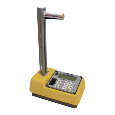
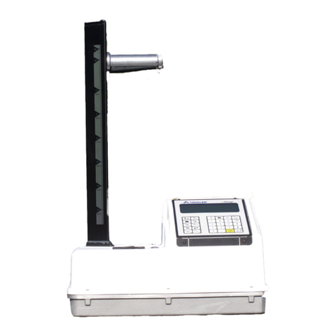
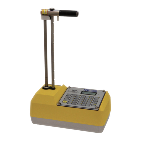
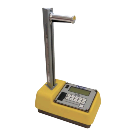
Troxler RoadReader 3430 User manual

Manual of Operation and Instruction
Troxler PlusLoader
For Loading Calibration
Constants into Troxler
Model 3430, 3440, and
3451 Gauges
Troxler Electronic Laboratories, Inc.
3008 Cornwallis Rd. •P.O. Box 12057
Research Triangle Park, NC 27709
Phone: 1.877.TROXLER
Outside the USA: +1.919.549.8661
Fax: +1.919.549.0761
www.troxlerlabs.com

ii
Troxler products are protected by U.S. and foreign Patents
Copyright 2015
Troxler Electronic Laboratories, Inc.
All Rights Reserved
No part of this manual may be reproduced or transmitted in any
form or by any means, electronic or mechanical, including
photocopying, recording, or information storage and retrieval
systems, for any purpose without the express written
permission of Troxler Electronic Laboratories, Inc.
PN 110190
December 2015
Edition 2.0

Model 4590 iii
TROXLER SERVICE CENTERS
Troxler Corporate Headquarters
P.O. Box 12057
Research Triangle Park, NC 27709
Phone: 1.877.TROXLER (1.877.876.9537)
Outside the U.S.A.: +1.919.549.8661
Fax: +1.919.549.0761
Technical Support
Phone: 1.877.TROXLER
(1.877.876.9537)
TroxTechSupport@troxlerlabs.com
North Carolina Service Center
3008 E. Cornwallis Road
Research Triangle Park, NC 27709
Phone: +1.919.549.8661
Fax: +1.919.549.0761
TroxTechSupport@troxlerlabs.com
Florida Office & Service Center
2376 Forsyth Road
Orlando, FL 32807
Phone: +1.407.681.4221
Fax: +1.407.681.3188
TroxTechSupport@troxlerlabs.com
Midwestern Office & Service Center
1430 Brook Drive
Downers Grove, IL 60515
Phone: +1.630.261.9304
Fax: +1.630.261.9341
TroxTechSupport@troxlerlabs.com
Western Office & Service Center
11300 Sanders Drive, Suite 7
Rancho Cordova, CA 95742
Phone: +1.916.631.0234
Fax: +1.916.631.0541
TroxTechSupport@troxlerlabs.com
Southwestern Office &
Service Center
2016 East Randol Mill Rd., Suite 406
Arlington, TX 76011
Phone: +1.817.275.0571
Fax: +1.817.275.8562
TroxTechSupport@troxlerlabs.com
Troxler Europe & Service Center
Troxler Electronics GmbH
Gilchinger Strasse 33 D.82239
Alling nr. Munich, Germany
Phone: ++ 49.8141.71063
Fax: ++49.8141.80731
troxler@t-online.de
Troxler Electronic Technologies
(Zhangjiagang)
1F, Bldg G, No. 1 Guotai North Road
ZJG, China, 215600
Phone: 0086.512.56793702
Fax: 0086.512.56793701
kjin@troxlerlabs.cn
To locate an independent, Troxler-authorized service partner
near you, call 1.877.TROXLER (1.877.876.9537).

iv
TABLE OF CONTENTS
CHAPTER 1: WHEN WOULD I NEED PLUSLOADER ...........................7
Introduction ...................................................................................................8
CHAPTER 2: INSTALLING AND ACTIVATING THE SOFTWARE.........11
Installing the PlusLoader ..........................................................................12
Activating the PlusLoader........................................................................13
CHAPTER 3: PREPARING THE GAUGE TO ENTER CONSTANTS ......15
Connect Gauge to the Computer .........................................................16
CHAPTER 4: LOADING AND READING THE CALIBRATION .............17
Loading the Calibration Constants into the Gauge..........................18
Reading the Calibration Constants from the Gauge........................27
CHAPTER 5: CHECKING THE LICENSE STATUS ................................30
APPENDIX A: PLACING THE GAUGES IN CLI MODE..........................31
Putting Models 3430 Plus, 3440 Plus, and 3440 Enhanced in CLI
Mode .............................................................................................................32
Putting the Troxler Model 3430 Enhanced in CLI Mode ................33
APPENDIX B: UPLOADING CALIBRATION CONSTANTS TO PDA......34
Uploading Calibration Constants (Model 3451 Only)......................35

Model 4590 v
LIST OF FIGURES
Figure 1: 3440 Plus Gauge ........................................................................9
Figure 2: 3440 "Legacy" Gauge............................................................. 10
Figure 3: Opening Window, PlusLoader............................................. 12
Figure 4: Activation Screen..................................................................... 13
Figure 5: PlusLoder Main Menu............................................................ 18
Figure 6: Communications Port Selection Screen............................ 19
Figure 7: Gauge Model Selection Screen........................................... 19
Figure 8: Query Regarding Whether to Read Calibration
Constants from Gauge ............................................................................ 20
Figure 9: Data Entry Screen for Model 3430 or 3440, Plus or
Enhanced..................................................................................................... 21
Figure 10: Opening Data Screen for Model 3451. ......................... 22
Figure 11: Second Data Entry Screen (Thin Layer Data) for Model
3451. ............................................................................................................. 23
Figure 12: Communications Protocol Initialization Prompt. ........ 24
Figure 13: Security Check Confirmation ............................................. 24
Figure 14: Calibration Storage Complete Message......................... 25
Figure 15: Calibration Data Passed to Gauge Message................. 25
Figure 16: License Status Display Screen............................................ 26
Figure 17: Calibration Constants Complete Message..................... 28
Figure 18: Example Downloaded Constants Screen ....................... 29
Figure 19: Socket™ Bluetooth™ Cordless Serial Adapter.............. 36

vi
Figure 20: Socket
Bluetooth
cordless serial adapter
installed in the gauge............................................................................... 36
Figure 21: Intermec® 700 Color mobile computer ....................... 37
Figure 22: Pocket PC Opening Screen .............................................. 38
Figure 23: Pocket PC Initialization Screen.......................................... 38
Figure 24: Pocket PC Gauge Status Screen...................................... 39
Figure 25: Gauge Warmup Screen ..................................................... 39
Figure 26: RoadReader Plus Main Menu for Pocket PC. .............. 40
Figure 27: Pocket PC Gauge Tools Menu ......................................... 40
Figure 28: Pocket PC Diagnostic Menu ............................................. 41
Figure 29: Pocket PC Diagnostic Menu with Dropdown Menu ... 41
Figure 30: Service Code Input Box...................................................... 42
Figure 31: Pocket PC Service Menu.................................................... 42
Figure 32: Pocket PC Calibration Constants Menu ........................ 43
Figure 33: Pocket PC Calibration Constants Collection Screen.... 44
Figure 34: Calibration data transfer from the gauge to the Pocket
PC was successful...................................................................................... 44

Model 4590 7
Chapter 1:
When Would I Need
PlusLoader
This chapter covers the purpose of the PlusLoader
and when it is needed.

8
Introduction
For added security and data confidentiality and control, the
following gauges do not allow the user to enter calibration
constants manually into the gauge through the keypad:
•Model 3430 Plus
•Model 3440 Plus
•Enhanced Model 3430
•Enhanced Model 3440
•Model 3451
There are only two ways to load calibration constants into these
gauges: either the full Troxler calibration software program
specific to these gauges, or the PlusLoader program.
A distinct visual characteristic with which one can easily
distinguish between the Plus or Enhanced models of the 3430
and 3440 (which do require the PlusLoader) and the “Legacy”
versions of the 3430 and 3440 (which do not require the
PlusLoader and allow the user to enter calibration constants
manually into the gauge through the keypad) is the source rod
tower. Specifically, the Plus and Enhanced models of the 3430
and 3440 have a triangular shaped source rod tower as shown
here:

Model 4590 9
Figure 1: 3440 Plus Gauge
Note the triangular source rod tower. The 3430 Plus, the 3430
Enhanced, and the 3440 Enhanced also have this same tower
design.
By contrast, the “Legacy” versions of the Troxler Model 3430
and 3440 do not have a triangular shaped source rod tower, but
rather a cylindrical, notched index rod parallel to and adjacent
to the cylindrical source rod, neither of which is enclosed in a
tower assembly:

10
Figure 2: 3440 "Legacy" Gauge
Note the cylindrical source rod (the leftmost rod) and the
adjacent, likewise cylindrical index rod.

Model 4590 11
Chapter 2:
Installing and Activating
the Software
This chapter covers the following topics and tasks:
Installing the PlusLoader
Activating the PlusLoader

12
Installing the PlusLoader
The Troxler PlusLoader program must be installed, then
activated, before it can be used to load calibration constants into
a Troxler gauge.
1. The first step in the process is to contact the Sales
Department at Troxler Electronic Labs to purchase a
specific number of uses for the PlusLoader program. A
“use” consists of one successful upload of calibration
constants into the gauge.
2. Once the purchase is complete, Troxler will provide you
with a link to the installation application for the
program. Download this application from the provided
link.
3. Run the installation program.
4. When the installation is complete, go to the “Troxler
Plusloader” program group in Windows and double-
click the “PlusLoader” icon.
5. When the PlusLoader program loads for the first time,
the following screen displays.
Figure 3: Opening Window, PlusLoader

Model 4590 13
Activating the PlusLoader
If you wish to view online instructions for product activation,
including an instructional video, then click the “Go To Website”
link.
1. Click the green “Activate Troxler Plusloader…” button,
an Activation Screen similar to the following displays:
Figure 4: Activation Screen
2. Email the “User Code 1” and “User Code 2” values back
to your Sales contact at Troxler that sent you the link.
3. Troxler will reply to your application in the form of an E-
mail that has the “Activation Code 1” and “Activation
Code 2” values you will need.
4. Once you get the activation codes from Troxler, re-start
the PlusLoader program and return to the Activation
Screen shown in Figure 4.
5. Enter the Activation Codes you received from Troxler in
the spaces provided on the Activation Screen.

14
6. Once you enter the Activation Codes, the “Continue”
button on the screen becomes active. Click “Continue”,
and the software activates.

Model 4590 15
Chapter 3:
Preparing the Gauge to
Enter Constants
Once the software is registered and activated, the process of
loading calibration constants into the gauge can proceed. In
order to load the constants into your gauge, however, your will
require two pieces of hardware:
oRS-232 port on your computer, or a USB port on your computer
and an RS-232 serial to USB adapter. Most currently manufactured
computers do not come with an RS-232 PCI card as standard
equipment. Purchasing an RS-232 PCI card to install in your
computer, or purchasing an RS-232 serial to USB adapter to plug
into an available USB port on your computer, are options. Neither
of these hardware devices is particularly expensive or difficult to
install. Please keep in mind that if you purchase a RS-232 serial to
USB adapter that you have not used before in your computer, you
will have to install the driver that comes with the adapter.
oRS-232 cable to connect between the gauge and the computer’s
RS-232 port. If you are using this software to load calibration
constants into a Troxler Model 3451 gauge, this cable will have to
be a regular RS-232 cable (with a DB9 female connector on one
end and a DB9 male connector on the other.) If instead you are
using a Troxler Model 3430 or 3440 gauge, the cable will have to
be an RS-232 null modem cable with full handshaking (Troxler Part
No. 106514), with a DB9 female connection on both ends.

16
Connect Gauge to the Computer
Before one can load the calibration constants into the gauge,
the gauge must be connected to the computer and the gauge
must be ready to communicate with the computer. In order to
make these preparations, please do the following
1. Turn on the gauge. If the gauge is a Model 3430 or a Model
3440, allow the gauge to complete the self-check, but you
can skip the 300 second warm-up period.
2. Connect the proper RS-232 cable between the gauge and the
computer. Take note of the number assigned to the
computer communications port that you are using (if you
have more than one port.) This can be done from the
Windows Device Manager.
3. If the gauge is a Model 3451, there is no further preparation
required; proceed to Chapter 4: Loading and Reading the
Calibration to begin the process of loading the calibration
constants into the gauge.
4. If the gauge is a Model 3430 or 3440, however, the gauge
must be put into Command Line Interface (CLI) mode in
order for the communications between the gauge and the
computer to work.
oIf the gauge is a Model 3440 Enhanced, a Model 3440
Plus, or a Model 3430 Plus, then refer to Section
“Putting Models 3430 Plus, 3440 Plus, and 3440
Enhanced in CLI Mode” in Appendix A for instruction
in performing this task.
oIf the gauge is a Model 3430 Enhanced, then refer to
Section “Putting the Troxler Model 3430 Enhanced
in CLI Mode” in Appendix A for instructions on
performing this task.
5. Once the gauge is in CLI mode, the gauge software and
hardware configurations are ready for loading constants;
proceed to Chapter 4: Loading and Reading the Calibration
to begin the process of loading or reading the calibration
constants.

Model 4590 17
Chapter 4: Loading and
Reading the Calibration
This chapter covers the following topics and tasks:
Loading the Calibration Constants into the Gauge
Reading the Calibration Constants from the Gauge

18
Loading the Calibration Constants
into the Gauge
Once the PlusLoader is downloaded and activated, the
calibration constants can be loaded into the gauge from the
PlusLoader program. If the user wishes to re-use some of the
calibration constant that are currently in the gauge from a
previous calibration, this step in the process allows them to do
this task automatically. However, if there are calibration
constants that the user wishes to enter into the gauge that are
not already in the gauge from a previous calibration, the user
must have these new values available at this point.
To load the calibration constants into the gauge:
1. Click the Windows Start button, then select the All
Programs menu and the Troxler PlusLoaderProgram
group.
2. From the Troxler PlusLoader Program group, select the
PlusLoader program.
3. At this point the PlusLoader Main Menu displays (see Figure
5.)
Figure 5: PlusLoder Main Menu
4. Select the option “Upload Calibration constants to a Troxler
Model 3430 Plus, 3440 Plus, or 3451”, then click the
“Proceed” button.

Model 4590 19
5. The program now prompts the user to select the RS-232
communication port through which the computer is
connected to the gauge. All available communications ports
are listed on the Communications Port Selection Screen (see
Figure 6.)
Figure 6: Communications Port Selection Screen
6. Select the appropriate port number, and then click the
“Proceed” button.
7. After the communications port is selected, the Gauge Model
Selection Screen displays (see Figure 7.)
Figure 7: Gauge Model Selection Screen
8. Select the gauge model, and then click the “Proceed” button.
9. At this point the Calibration Constants Initial Readout Query
screen (see Figure 8) displays.

20
Figure 8: Query Regarding Whether to Read Calibration
Constants from Gauge
If the initial readout option is selected, then the computer
reads the calibration constants that are currently in the
gauge and “pre-load” the values into the data entry screens.
This option is useful if you plan to re-use some of the
current calibration constants in the new calibration, but
would only create more work if you do not plan to re-use.
If the initial readout option is declined, then skip the next
step and proceed to Step (11). If the initial readout option is
accepted, however, then proceed to the next step
10. The program now reads the calibration constants out of the
gauge and prepares them for display. Once the data are
read from the gauge, a message box stating “Calibration
Constants Complete” displays. Click “Ok” on that message
box and proceed to the next step.
11. At this point the Opening Data Entry Screen displays.
If the gauge is a Model 3430 or 3440, it looks similar to
Figure 9.
Other manuals for RoadReader 3430
3
This manual suits for next models
2
Table of contents
Other Troxler Measuring Instrument manuals

Troxler
Troxler RoadReader Plus 3450 User manual

Troxler
Troxler EGauge 4590 User manual

Troxler
Troxler 3400-B Series User manual

Troxler
Troxler TroxAlert User manual

Troxler
Troxler EGauge Combo 4540 User manual

Troxler
Troxler 3430 Plus User manual

Troxler
Troxler 3440-L User manual

Troxler
Troxler 3241 Series User manual
Troxler
Troxler EGauge Combo 4540 User manual

Troxler
Troxler RoadReader 3430 Guide