Kysor/Warren QDV5V14 User manual

Part Number: 31E11003
Date Revised: 03-11-2009
5201 Transport Boulevard
Columbus, GA 31907
706-568-1514
Installation
&
Operation
Manual
QDV5V(1)(3)4/Medium Temperature
QIV5V(1)(3)4/Low Temperature
Reach-In Display Cases
with modular condensing unit
IMPORTANT – KEEP IN STORE FOR FUTURE USE

3/11/2009 2

3/11/2009 3
Table of Contents
Introductions – General Information ................ 4
Case Description............................................... 4
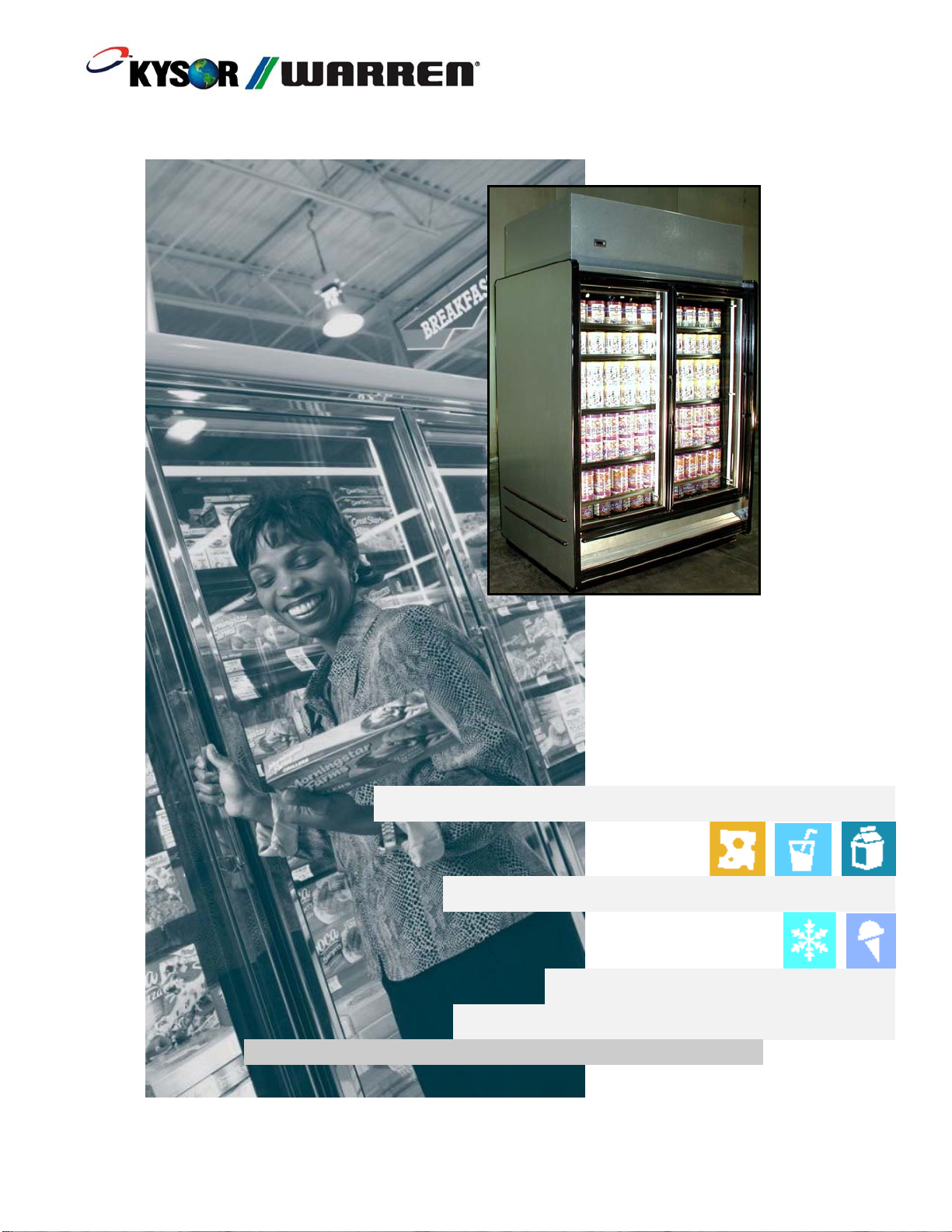
Standard Reach-in Case................................ 4
Receiving/Shipping Damage/Lost Items .......... 5
Refrigerant ........................................................ 5
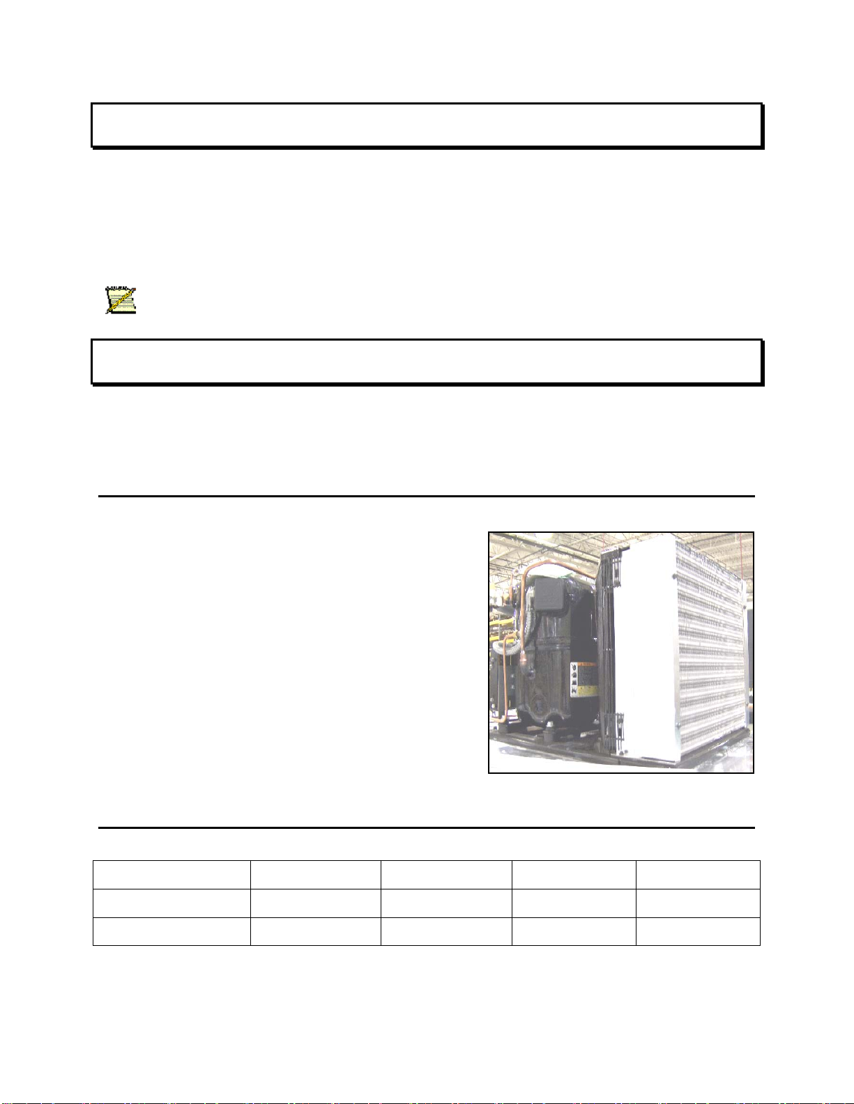
Modular Condensing Unit: ........................... 5
Refrigerant Charge........................................ 5
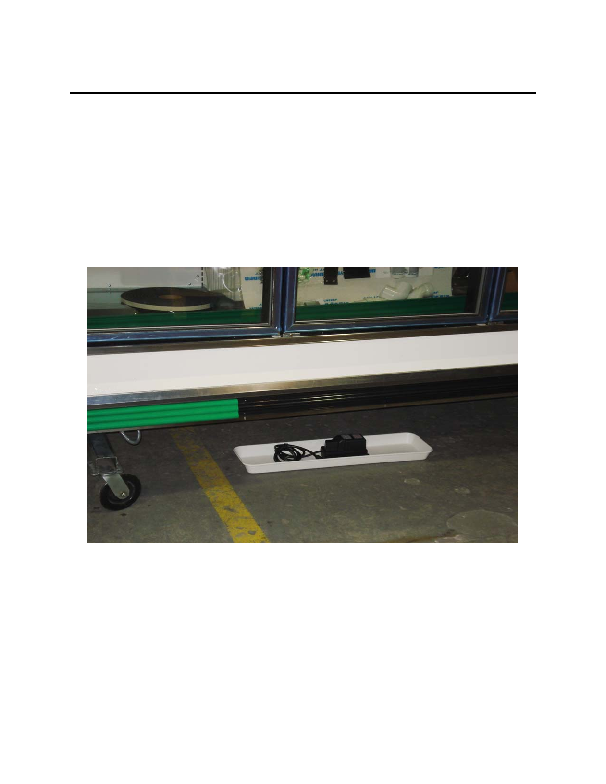
Condensate Pump.......................................... 6
Case Controller ............................................. 7
Programming Paragon Case Controller........ 8
Condensate Evaporator Pan Heater ............ 13
Buck & Boost Transformer (optional)........ 13
Plan View and Cross Section.......................... 15
Case Data........................................................ 16
Case Installation.............................................. 18
Preparation (with modular condensing unit)18
Installation....................................................... 18
Unpacking................................................... 18
Installing Assembly .................................... 19
Modular Condensing Unit............................... 20
Mounting Base & Enclosure....................... 20
Refrigeration Connections.......................... 22
Coupling Connection Instructions .......... 22
Initial Connections.................................. 23
Coupling Description.............................. 25
Waste Outlet (Drip Pipe) Description and
Location .................................................. 29
Drain Strainer.......................................... 29
Electrical Connections – General.................... 30
Electrical Termination ................................ 30
Wiring Diagrams......................................... 30
Fan Relay Assembly/Wiring....................... 34
Expansion Valve and Superheat ..................... 35
Operation......................................................... 36
Loading....................................................... 36
Normal Operation (with modular
condensing unit).......................................... 36
Cleaning...................................................... 37
Parts Drawing.............................................. 40
Parts List –
QDV5V(14)(34)/QIV5V(14)(34)............... 41
Warranty ......................................................... 42
Parts Warranty Policy................................. 42
New Equipment Parts Shortages and
Defects ........................................................ 42
Parts Ordering Procedure............................ 42
Return Authorization Procedure................. 42
One-Year Warranty..................................... 43

3/11/2009 4
Introductions – General Information
This manual has been prepared for our customers and the personnel involved in setting up and
maintaining our cases.
The Kysor//Warren case is designed to provide years of
trouble free service. The glass door reach-in cases are
designed to merchandise frozen food, ice cream, and medium
temperature products. Basic designs are 2, 3, 4, or 5 door
cabinets for each of the models listed below. Each of these
cases has an optional modular condensing unit.
These cases should be installed and operated according to the
instructions contained in this manual to insure proper
performance. They are designed for display of products in an
air-conditioned store where temperature and humidity are maintained at a maximum of 75º dry
bulb temperatures and 55% relative humidity.
Case Description
Standard Reach-in Case
The standard Reach-In Cases will have the following features as default options with an
additional option, a Modular Condensing Unit:
• Anthony Eliminator Doors
• Top/Rear Piping (Pipe Line sized to the Case spec)
• Top Wiring
• Suction to liquid line heat exchanger
• All Low Temp Cases are Electric Defrost (208V/60Hz/1Ph),
• Medium Temp Cases are Off Cycle Defrost
Model Description
QDV5V(14)(34) Upright/Glass Door Medium Temp Merchandiser
(Off-Cycle Defrost) Vertical Lighting/Eliminator Door
QIV5V(14)(34) Upright/Glass Door Ice Cream Merchandiser
(Electric Defrost) Vertical Lighting/Eliminator Door
Icon Key
Caution
Special Note
Warning

3/11/2009 5
Receiving/Shipping Damage/Lost Items
All equipment should be examined for shipping damage before and during unloading. If there is
any damage, the carrier should be notified immediately and an inspection requested. The
delivery receipt must be noted that the equipment was received damaged. If damage is of a
concealed nature, you must contact the carrier within three (3) days following delivery. The
consignee for all damages must file a claim with the carrier.
Note: All claims for shortages must be within 10 days after receipt of shipment.
Refrigerant
The QDV5V(14)(34) medium temperature and QIV5V(14)(34) low temperature cases use
R404A refrigerant.
Modular Condensing Unit:
The selected Condensing Unit will have following default features
• Electrical rating of 208-230V/60Hz/1Ph
• Refrigerant R404A
• Manual Reset High Pressure Safety Cut-Out
• Receiver and Suction Valve
• All Refrigeration Lines Sweat Connections
• Each Condensing Unit designed to operate one Case
• Condensing units are UL Listed
Refrigerant Charge
MODEL 2 Door 3 Door 4 Door 5 Door
QDV5V14 3.75 Lbs 4.50 Lbs 5.80 Lbs 7.2 Lbs
QIV5V14 4.75 Lbs 5.5 Lbs 8.25 Lbs 11.20 Lbs

3/11/2009 6
Condensate Pump
The Condensate Pump is a compact, submersible pump with a built-in, hermetically sealed,
pressure activated switch. It has following features
• Electrical rating of 120V/60Hz/1Ph, 0.9A
• Capacity: 45GPH @ 10’ of head
• Quiet operation
• Pump operates automatically when water level reaches approx 1.2” & turns off at .75”
• Pump is field installed into a 3-gallon drain pan
• Pump is UL Listed

3/11/2009 7
Case Controller
A Paragon Case Controller is provided to control the compressor, fan, and case defrosts.
• Temperature Control - When the case reaches the desired discharge air temperature, the
controller shuts off the compressor. When the discharge air temperature increases above the cut-
in set point, the compressor turns on.
• Compressor Control – Compressor operating parameters such as minimum off time,
minimum run time and start-up time delay are field adjustable.
Remote Display

3/11/2009 8
Programming Paragon Case Controller
To program the case controller, remove cover from Paragon display so the display LED is
visible. The display must be as shown below:

3/11/2009 9

3/11/2009 10
Continued on next page

3/11/2009 11

3/11/2009 12
PLEASE USE BELOW VALUES WHILE PROGRAMMING:
QDV5V14 (Med Temp Cases):
1. Adjust the correct time of the day.
2. Discharge Air Temp – Set (cut out): 32’F
3. Display Status: rSP’ – Discharge Temperature
4. Defrost Type: dFtP – Select ELEC for Electric Defrost/Off Cycle Defrost
5. Fan Status During Defrost – Select Default (Fan will not be controlled through the Case
Controller)
6. Defrost Interval: dFIN – tdAy
7. Number of Defrosts: nodF: 1 per day
8. Defrost Start Time: dEF1 – Set the desired Defrost Time

3/11/2009 13
9. Defrost Duration: dEFd: 30 Min
10. Defrost Termination Temp: dEF’: 40’F
11. Set point Differential: diF’: 4’F
QIV5V14 (Low Temp Cases):
1. Adjust the correct time of the day
2. Discharge Air Temp – Set (cut out): -12’F
3. Display Status: Select rSP’ – Discharge Temperature
4. Defrost Type: dFtP – Select ELEC for Electric Defrost/Off Cycle Defrost
5. Fan Status During Defrost – Select Default (Fan will not be controlled through the Case
Controller, will be controlled Current Sensing Relay & Fan Delay Thermostat
6. Defrost Interval: dFin – tdAy
7. Number of Defrosts: nodF: 1 per day
8. Defrost Start Time: dEF1 – Set the desired Defrost Time
9. Defrost Duration: dEFd: 45Min
10. Defrost Termination Temp: dEF’: 65’F
11. Set point Differential: diF’: 4’F
Condensate Evaporator Pan Heater
The Condensate Evaporator Pan Heater has following features
• Electrical rating of 120V/60Hz/1Ph, 8.3A, 1000 W
• Condensate dissipation rate: 8.5 Gallons per day
• 3 Gallon Evaporator Pan
• Evaporator Pan Heater is UL Listed
Buck & Boost Transformer (optional)
A 1.5 KVA Buck & Boost transformer is an available option. The
primary and secondary of Buck & Boost transformer can be
interconnected for use as an autotransformer to slightly step up or
down voltages. When used as an autotransformer to slightly adjust
voltage, the Buck & Boost Transformer can carry loads in excess of
its nameplate rating.
Example: With the transformer wired to provide 208V output with 195V input, the load
capacity of the transformer is 19.5KVA.

3/11/2009 14
When the Buck & Boost transformer option is chosen, the transformer is factory wired to provide
208V output with 195V input. The transformer connections can be rewired in the field to
provide alternative buck and boost percentages. Wiring instructions are provided on the
transformer cover. Transformer is UL listed.

3/11/2009 15
Plan View and Cross Section
QDV5V(14)(34) and QIV5V(14)(34)

3/11/2009 16
Case Data
QIV5V(14)(34) – Low Temp – Eliminator Door With Modular Condensing Unit
115V Circuit Data 2 Door 3 Door 4 Door 5 Door
Power Supply 115/1/60
Anti-Sweat Amps (ELM Door) 2.43 3.32 4.40 5.44
Evap Fan Motor Amps (PSC opt) 0.44 0.66 0.88 1.10
Evap Fan Motor Amps (EMC opt) 0.40 0.60 0.80 1.00
Light Amps (T8) 1.39 1.80 2.32 2.79
LED Light Amps (Gelcore opt) 0.70 1.05 1.40 1.73
Drain Pan Heater 0.39 0.65 0.91 1.17
Condensate Pump Amps 0.94 0.94 0.94 0.94
Condensate Evaporator Amps 8.00 8.00 8.00 8.00
Minimum Circuit Amp 13.83 15.61 17.69 19.68
Maximum Overcurrent Protection 20.00 20.00 20.00 20.00
208V Circuit Data 2 Door 3 Door 4 Door 5 Door
Power Supply 208/1/60
Compressor RLA 9.60 11.40 11.4 16.7
Compressor LRA 59.20 59.20 59.2 87.0
Condenser Fan Motor Amps 0.85 2.60 1.70 5.20
Defrost Heaters Amps 6.09 9.13 12.17 15.22
Minimum Circuit Amp 12.85 16.85 15.95 26.10
Maximum Overcurrent Protection 15.00 20.00 20.00 20.00
Horse Power 1 2 2 ¼ 3
DEFROST CONTROLS
Defrost Per Day Fail Safe Termination
Electric 1 45 min 65°F
BTU Per Door
PSC Fan 820
ECM Fan 780
NOTE: For sizing conventional/individual condensing units. Maintained
temperature -5°F.
Discharge Air Velocity Discharge Air Temp
300 FPM -5/-12 °F

3/11/2009 17
QDV5V(14)(34) – Med Temp – Eliminator Door With Modular Condensing Unit
115V Circuit Data 2 Door 3 Door 4 Door 5 Door
Power Supply 115/1/60
Anti-Sweat Amps (ELM Door) 0.81 1.17 1.57 1.91
Evap Fan Motor Amps (PSC opt) 0.44 0.66 0.88 1.10
Evap Fan Motor Amps (EMC opt) 0.40 0.60 0.80 1.00
Light Amps (T8) 1.67 2.22 2.78 3.34
LED Light Amps (Gelcore opt) 0.70 1.05 1.40 1.73
Condensate Pump Amps 0.94 0.94 0.94 0.94
Condensate Evaporator Amps 8.00 8.00 8.00 8.00
Minimum Circuit Amp 12.10 13.23 14.41 15.53
Maximum Overcurrent Protection 15.00 20.00 20.00 20.00
208V Circuit Data 2 Door 3 Door 4 Door 5 Door
Power Supply 208/1/60
Compressor RLA 4.20 5.70 5.70 5.70
Compressor LRA 16.80 24.10 24.10 24.10
Condenser Fan Motor Amps 0.70 0.70 0.70 0.70
Minimum Circuit Amp 5.95 7.83 7.83 7.83
Maximum Overcurrent Protection 10.00 10.00 10.00 10.00
Horse Power 1/3 1/2 1/2 1/2
DEFROST CONTROLS
Defrost Per Day Fail Safe Termination
Off Cycle 1 30 min 40°F
BTU Per Door
PSC Fan 820
ECM Fan 780
NOTE: For sizing conventional/individual condensing units. Maintained
temperature +38°F.
Discharge Air Velocity Discharge Air Temp
300 FPM +32 °F
Note: Temperature is measured in discharge air. Defrost frequency is at design
conditions. Higher temperature or humidity may require more defrost and longer fail-safes.
Maximum 75 ºF and 55% humidity continuously is recommended for the efficiency of your case.
Refer to www.kysorwarren.com for other electrical data and information.

3/11/2009 18
Case Installation
The display cases are installed individually.
Preparation (with modular condensing unit)
Prepare the installation area as follows:
1. Clean area where case is to be installed.
2. Verify installation area is at least 15 feet from any outside entrances or heating and cooling
outlets.
3. Verify at least 2 feet distance between hot and cold cases.
Caution: To prevent condensation on the end panels of cases, a minimum of 6.0 inches
between walls or other cases is required for airflow. If 6.0 inches is not possible, then the space
between the cases must be completely filled and sealed or an updraft fan kit must be installed to
provide air circulation through the space.
4. Ensure floor loading will support the case and the case contents.
5. Ensure proper AC power is available. Refer to case AC input requirements located in the
electrical connections section of this manual.
6. Ensure that R404A Refrigerant is available at the installation site.
Installation
The following instructions are provided for unpacking, moving, loading, and lifting the case
prior to installation.
Note: READ ALL INSTRUCTIONS CAREFULLY BEFORE BEGINNING
INSTALLATION
Unpacking
1. Remove all shipping tape from lamps and ensure that all lamp ends are snapped in place.
Caution: Use caution when removing the strapping in the following procedure, as the
shelves are very heavy and could fall causing personal injury or equipment damage.
2. Ensure the evaporator cover is installed correctly and the deck pans are installed.
3. Move the case into position.

3/11/2009 19
Caution: Be careful not to damage the factory-installed end while moving the case. Use
the case lift points on the case to move it to the proper location.
Installing Assembly
1. Ensure all preparation for installation, as outlined in the above paragraphs, have been fully
complied with and are complete.
2. Allow a minimum of 6 inches between the rear of the case and the store walls and/or other
cases. This space reduces the possibility of condensation problems. It may be necessary to
provide forced air ventilation in some installations.
3. All cases must be located on a firmly based floor and leveled within plus or minus 1/16 in.
4. Use shims provided to support and level the entire length of your case(s). All rails of the case
must be properly shimmed and in contact with the floor. Cases with shims on the ends must also
have shims in the middle and no more than 4 ft. apart. All legs of the case must be properly
adjusted and in contact with the floor.
5. If multiple cases are to be installed, refer to the floor plan and install the first case in the line
up by snapping a chalk line where the front and rear of the cases are to be located.
6. Continue the chalk line if multiple cases are to be installed. The first case is typically the case
that is at the highest area on the floor.
7. Connect water drain line. Reference waste outlet (drip pipe) description and location
procedure later in this chapter.
8. Connect input AC power (SEE Case Data Section).
9. Set condensing unit on top of case at location supplied. Pipe into case using the sight glass
and liquid line filter drier supplied. Follow normal procedures for brazing; pressure testing, and
evacuation of the system. Once system has been evacuated charge system, program controller
and check for proper operation.
10. Remove shipping tape on fluorescent lamps and remove all other shipping material
CASES MUST BE LEVELED FROM FRONT TO BACK END-TO-END AND SUPPORTED
CONTINUOUSLY AS NEEDED WITH SHIMS.

3/11/2009 20
Modular Condensing Unit
Mounting Base & Enclosure
The evaporator pan, control box, and Buck & Boost transformer are factory mounted on a base
plate attached to the top of the case. Condensing unit, enclosures panels, sight glass, & liquid
line filter drier are shipped loose and
Will be field installed. (Refer to pictures below)
Assembly – Modular Condensing Case
The front enclosure panel has a knock out provided for the controller display.
This panel must face the front of the case
This manual suits for next models
1
Table of contents
Other Kysor/Warren Refrigerator manuals