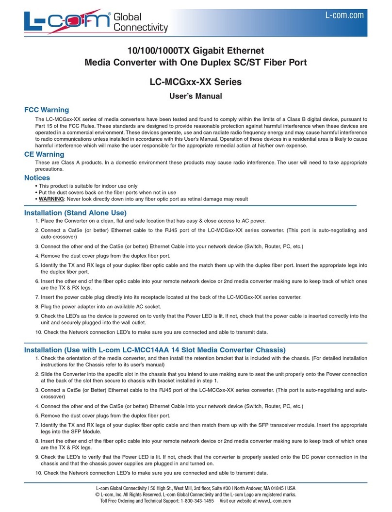
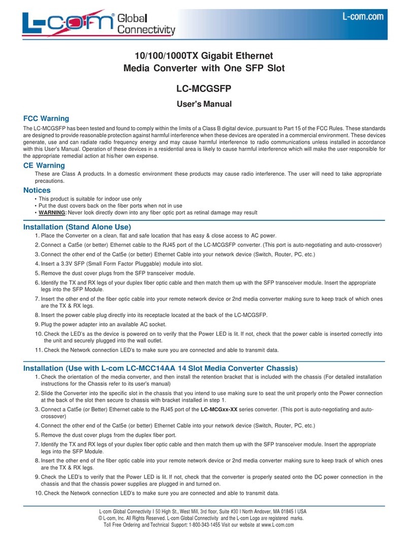
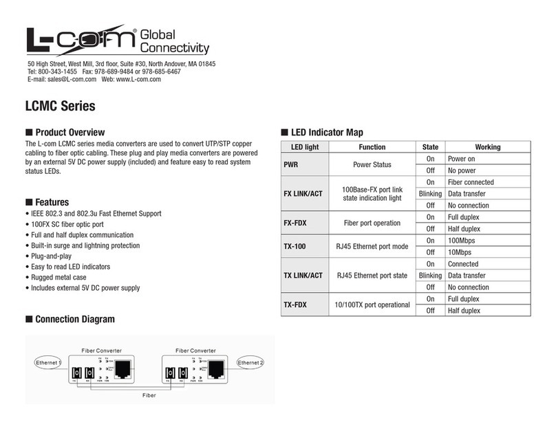
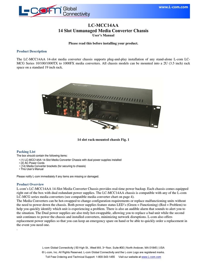
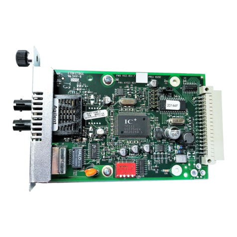
l-com LCTP-10BT-10B2 User manual

L-com, Inc. 50 High St., West Mill, 3rd Floor, Suite #30 North Andover, MA 01845
© L-com, Inc. All Rights Reserved. L-com Global Connectivity and the L-com logo are registered marks.
10 Base-2/T
Converter
LCTP-10BT-10B2
Installation Guide

FCC WARNING
COPYRIGHT
WARRANTY
All rights reserved. No part of this publication may be reproduced,
stored in a retrieval system, or transmitted in any form by any
means, whether electronic, mechanical, photo copying, recording or
otherwise, without the prior written permission of the publisher.
This equipment has been tested and found to comply with the limits
for a class A device, pursuant to part 15 of FCC rules. These limits
are designed to provide reasonable protection against harmful
interference in a commercial installation. This energy and, if not
installed and used in accordance with the instructions, may cause
harmful interference, in which case, the user will be required to
correct the interference at user's own expense.
Due to the confidence of the quality of our products we are now
extending our warranty period to 1 year against any defects in
workmanship.
Note: All guarantees for this product are in effect providing it is
used in the manner it was intended. Damages caused by customer
misuse, abuse, and neglect will cause any implied or written
guarantees to be null and void.
*See "Terms and Conditions of Sales" for complete warranty
L-com, Inc. 50 High St., West Mill, 3rd Floor, Suite #30 North Andover, MA 01845
© L-com, Inc. All Rights Reserved. L-com Global Connectivity and the L-com logo are registered marks.

L-com, Inc. 50 High St., West Mill, 3rd Floor, Suite #30 North Andover, MA 01845
© L-com, Inc. All Rights Reserved. L-com Global Connectivity and the L-com logo are registered marks.
CONTENTS
I. Overview ............................................................................1
II. Thin Ethernet Termination Switch .....................................2
III. 10Base-T Connection Switch.............................................3
IV. LED Indications .................................................................4
V. Set-Up Procedures.......................................................... 5-6
VI. Troubleshooting..................................................................7
VII. Specifications .....................................................................8

L-com, Inc. 50 High St., West Mill, 3rd Floor, Suite #30 North Andover, MA 01845
© L-com, Inc. All Rights Reserved. L-com Global Connectivity and the L-com logo are registered marks. 1
OVERVIEW
This booklet is designed as a guide for the easy installation of
10Base-2 to 10Base-T Converter.
The 10Base-2/T Converter is designed to connect an
existing 10Base-2 Thin Ethernet adapter
card or 10Base-2 network to a 10Base-T
system. The converter works by simply
repeating the signals from 10Base-2 to a
suitable format for transmission over UTP
(Unshielded Twisted Pair) cables to a
10Base-T hub or workstation.
I. Overview

L-com, Inc. 50 High St., West Mill, 3rd Floor, Suite #30 North Andover, MA 01845
© L-com, Inc. All Rights Reserved. L-com Global Connectivity and the L-com logo are registered marks. 2
SWITCH
•ON - Set the terminator to the "ON" Position when the
converter is placed at the end of the segment. See set-up, page 5.
•OFF - Set the terminator to the "OFF" Position when the convertor
is placed in the middle of the segment. See set-up page 5.
II. Thin Ethernet Terminator Switch

3
SWITCH
•Hub Connection - Set the connection switch
to the Hub position connection.
•Workstation Connection - Set the connection
switch to the W/S position for a Workstation
connection.
1=TX+
2=TX-
3=RX+
6=RX-
III. Connection Switch
L-com, Inc. 50 High St., West Mill, 3rd Floor, Suite #30 North Andover, MA 01845
© L-com, Inc. All Rights Reserved. L-com Global Connectivity and the L-com logo are registered marks.

L-com, Inc. 50 High St., West Mill, 3rd Floor, Suite #30 North Andover, MA 01845
© L-com, Inc. All Rights Reserved. L-com Global Connectivity and the L-com logo are registered marks. 4
LEDs
•COL Each of the two collision indicators blinks when data collision
occurs at either the 10Base-T or 10Base-2 Port.
•LINK/RCV With this indicator ON, data link is
operating and converter is ready to receive data.
When this indicator blinks, data transmission is occurring on
the 10Base-T port.
•POWER This indicator is continuously "ON" while the converter
is receiving power from the external power adapter.
•BNC/RCV When this indicator is blinking, data is being received
from 10Base-2 Port.
IV. LED Indicators

5
SET-UP
Example I
• Converterisplacedontheendofasegment.
Procedure
• SetTerminatorSwitchto"ON"(50ohm).
• PlugcoaxialcableintoBNCconnector.
Example 2
• Converterisplacedonthemiddleofasegment.
Procedure
• SetterminatorSwitchto"OFF".
• PlugcoaxialcableintoBNCconnector.
V. Set-Up Procedures - 10Base-2 Connection
RJ-45
Converter
BNC
Connectors
Coaxial Cable
To 10Base-T Hub
or Workstation
Converter
BNC
Connectors
Coaxial Cable
RJ-45
To 10Base-T Hub
or Workstation
L-com, Inc. 50 High St., West Mill, 3rd Floor, Suite #30 North Andover, MA 01845
© L-com, Inc. All Rights Reserved. L-com Global Connectivity and the L-com logo are registered marks.

L-com, Inc. 50 High St., West Mill, 3rd Floor, Suite #30 North Andover, MA 01845
© L-com, Inc. All Rights Reserved. L-com Global Connectivity and the L-com logo are registered marks. 6
SET-UP
V. Set-Up Procedures - 10Base-T Connection
Converter
BNC Connectors
Hub
Thin Ethernet
Coaxial Cable
Unshielded
Twisted-Pair
Cable
BNC Connectors
Converter
Workstation
RJ-45
Thin Ethernet
Coaxial Cable
Unshielded
Twisted-Pair
Cable
Example I
• 10Base-THubConverter
Procedure
• SetTerminatorSwitchtoHubposition.
• ConnectRJ-45Jackwithpin-to-pinpatchcontrol.
Example 2
• 10Base-TWorkstationConnection.
Procedure
• SetconnectionswitchtoWorkstationposition.
• ConnecttheRJ-45Jackwithpin-to-pinpatchcord.

L-com, Inc. 50 High St., West Mill, 3rd Floor, Suite #30 North Andover, MA 01845
© L-com, Inc. All Rights Reserved. L-com Global Connectivity and the L-com logo are registered marks. 7
TROUBLESHOOTING
VI. Troubleshooting
Symptom Possible Solution
Power not "ON" Bad power connection Check external power adapter
LINK/RVC not
"ON"
- Wrong connection switch
- Bad connection
- Check Connection switch setting
- Check patch cord
COL LED Wrong termination setting Check Terminator setting
Check coaxial

L-com, Inc. 50 High St., West Mill, 3rd Floor, Suite #30 North Andover, MA 01845
© L-com, Inc. All Rights Reserved. L-com Global Connectivity and the L-com logo are registered marks. 8
SPECIFICATIONS
Standard
Interface
Cable Type
Technique
Standard
Terminator Switch
Connection Switch
Temperature
Humidity
Dimensions
Power Adapter
EMI
IEEE 802.3 10-Base-T, 10Base-2 standards
BNC connector for thin Ethernet
RJ-45Jackfor10Base-TEthernet
RG-58 coaxial cable for thin Ethernet connection;
Category 3, 4, or 5 UTP cable for 10Base-T UTP cable
Base band
IEEE 802.3 10Base-2 and 10 Base-T Ethernet
Two position (OFF or ON) for BNC
Two position switch for Hub or Workstation settings
0° to 55°C (Standard Operating)
10% to 90% (non-condensing)
4.2" x 2.2" x 0.8"
12V DC input, 1 Amp
Meets FCC Class A subpart B of Part 15 Requirements
VII. Specifications
Table of contents
Other l-com Media Converter manuals
Popular Media Converter manuals by other brands
CYP
CYP CDPS-4KQ-AD Operation manual
RSF Elektronik
RSF Elektronik AK MSS 25 1 Vss Mounting instructions
Extron electronics
Extron electronics VSC 200 user manual
AJA
AJA FS3 Installation and operation guide
Magewell
Magewell Ultra Encode User Manual, Reference and FAQ
VersaLogic
VersaLogic VL-EPH-V6 Reference manual
Microflex
Microflex 101-0010 Installation and operation manual
Visionary Solutions
Visionary Solutions Duet-2 user manual
Harman Kardon
Harman Kardon ADP 303 owner's manual
Sharp
Sharp RT-XV300H B C Service manual
TWERD Power Electronics
TWERD Power Electronics AFC200 user manual
Converters.TV
Converters.TV CCR-2SRGB Operation manual
