L3 Stormscope II Series User manual

User’s Guide
For the
Model WX-500
Aviation Products
Series II Weather Mapping Sensor
Stormscope®


iStormscope®WX-500 User’s Guide
Welcome
L3 Aviation Products one of the world’s most experienced companies
in airborne thunderstorm avoidance instruments, is pleased to
welcome you to the family of tens of thousands of pilots who are
enjoying the benets of safer ight with a Stormscope®weather
mapping system.
Fly with Greater Condence
You now own one of the leading instruments in the world for airborne
detection and mapping of thunderstorms. Unlike other products, your
new Stormscope sensor will enable you to make better informed
thunderstorm avoidance decisions so you can y more safely and
with greater condence than ever before.
The Original
Don’t be fooled by Stormscope system lookalikes. There is only
one Stormscope system, and only one company that makes the
Stormscope line of weather mapping systems. The Stormscope
system, the original, most accurate weather mapping system is
manufactured by L3 Aviation Products
Stormscope®System Advantages
Convenient Features
The advanced, patented technology in your new Stormscope sensor
was developed over many years and is so unique, so revolutionary, it
surpasses all others. Here are some of its features:
• Precisely maps electrical discharges up to 200 nmi away
• Provides for a 120° forward view and a 360° view of the
surrounding airspace
• Outputs both cell and strike data

ii Stormscope®WX-500 User’s Guide
Methods and apparatus disclosed and described herein have been
developed solely on company funds of L3 Aviation Products. No
government or other contractual support or relationship whatsoever
has existed which in any way affects or mitigates proprietary rights of
L3 Aviation Products in these developments. Methods and apparatus
disclosed herein may be subject to U.S. Patents existing or applied
for. L3 Aviation Products reserves the right to add, improve, modify,
or withdraw functions, design modications, or products at any time
without notice.
L3 Aviation Products
5353 52nd Street, S.E.
Grand Rapids, MI 49512 USA
Customer Support (800) 453-0288
International (616) 949-6600
FAX (616) 977-6898
www.L3aviationproducts.com
User’s Guide
WX-500
Document Part No. 009-11501-001, Revision D
Model: WX-500
© Copyright 2017
L3 Aviation Products
All Rights Reserved
Aviation Products
Distributed by:
Export Notice
This technical data is controlled under the Export Administration
Regulations (EAR) and may not be exported without proper
authorization by the U.S. Department of Commerce.
Stormscope®is a registered trademark of L3 Aviation Products

iiiStormscope®WX-500 User’s Guide
Document Precedence
This User’s Guide provides general information about the operation
of the WX-500 and the weather display. Refer to your FAA-approved
Airplane Flight Manual (AFM) and its ight manual supplements for
information specic to your aircraft. If there is conicting information
between the AFM and this guide, the AFM takes precedence over
this guide.
CAUTION
WARNING
Never use your Stormscope system to attempt to
penetrate a thunderstorm. The FAA Advisory Circular,
Subject: Thunderstorms, and the Airman’s Information
Manual (AIM) recommend that you “avoid by at least
20 miles any thunderstorm identied as severe or
giving an intense radar echo.”
Safety Summary
These warnings and cautions appear later in this guide and are
repeated here for emphasis:
There are several atmospheric phenomena other
than nearby thunderstorms which can cause isolated
discharge points in the strike display mode. Clusters
of two or more discharge points in the strike display
mode however do indicate thunderstorm activity
when they reappear after clearing the screen. Avoid
the clusters and you’ll avoid the thunderstorms. In
the cell display mode, even a single discharge point
may represent thunderstorm activity and should be
avoided.
Page 4-1
Page 4-1

iv Stormscope®WX-500 User’s Guide
Important Notice
All Stormscope® WX-500 functions are controlled through various
Multi-Function Displays (MFDs). The many capabilities of the WX-
500 allow MFD manufacturers to create screens compatible with the
various functions of their display. The display screens illustrated in
this guide are intended to be characteristic of a group of MFDs that
are congured to work with the WX-500. The examples are intended
to assist the pilot in interpreting lightning data output by the WX-500.
Each MFD shows the information consistent with the capabilities of
that particular display.
Revision Highlights
This revision D of the user’s guide updates the company name,
email/web addresses, and some format changes.

vStormscope®WX-500 User’s Guide
Table of Contents
Section Page
List of Illustrations ......................................................................................... vi
List of Tables ................................................................................................. vi
Chapter 1, System Description
General Description ....................................................................................1-1
Processor ...................................................................................................1-2
Antenna ......................................................................................................1-2
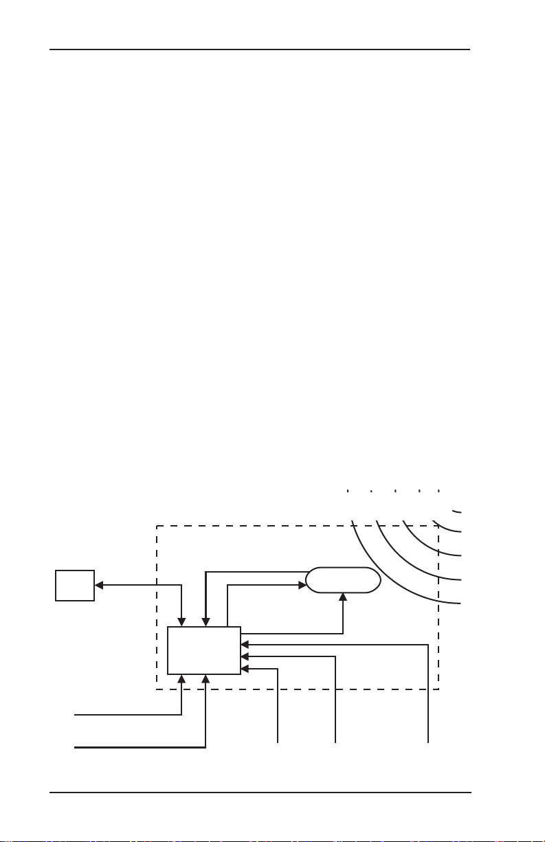
Functional Description ................................................................................1-2
Cell Data .....................................................................................................1-3
Strike Data ..................................................................................................1-3
Strike Rate ..................................................................................................1-3
Features . ....................................................................................................1-4
Chapter 2, Storm Mapping Principles
Anatomy of a Thunderstorm .......................................................................2-1
Stages of a Thunderstorm ..........................................................................2-3
The WX-500 & Weather Radar ...................................................................2-4
Chapter 3, Operation
Introduction .................................................................................................3-1
Power-Up.................................................................................................... 3-1
Continuous & Operator-Initiated Self Test ..................................................3-1
Clear All Discharge Points ..........................................................................3-2
Heading Stabilization ..................................................................................3-2
Error Messages ..........................................................................................3-2
Chapter 4, Weather Display Interpretation
Introduction .................................................................................................4-1
Radial Spread .............................................................................................4-2
Typical Patterns . .........................................................................................4-3
Mapping Headings Past Thunderstorms ....................................................4-6
Special Patterns ...................................................................................... 4-10
Chapter 5, Specications .........................................................................5-1

vi Stormscope®WX-500 User’s Guide
List of Tables
List of Illustrations
Table Title Page
3-1 Error Messages....................................................................................3-3
5-1 WX-500 Specications .........................................................................5-1
Figure Title Page
1-1 WX-500 Major Components .................................................................1-1
1-2 WX-500 Functional Diagram ................................................................1-2
2-1 Electrical Discharges in Thunderstorms ...............................................2-1
2-2 Discharge Rate a Function of Wind Shear ...........................................2-2
4-1 Airspace Diagram .................................................................................4-1
4-2 Three Clusters Within 200 nmi ............................................................ 4-3
4-3 Range Changed to 100 nmi ................................................................. 4-4
4-4 Two Clusters Within 200 nmi ................................................................4-5
4-5 Range Set at 200 nmi ...........................................................................4-6
4-6 Aircraft Progresses 100 nmi .................................................................4-7
4-7 Range Changes to 100 nmi ..................................................................4-8
4-8 Aircraft Turns to Avoid Thunderstorms ................................................. 4-9
4-9 Randomly Scattered Discharge Points ...............................................4-10
4-10 Cluster & Splattering Within 25 nmi...................................................4-11
4-11 Discharge Points Off the Aircraft’s Nose............................................4-12
4-12 Line of Discharge Points While Taxiing ............................................4-13
4-13 Developing Cluster Within 25 nmi ....................................................4-14

Stormscope®WX-500 User’s Guide 1-1
CHAPTER 1
SYSTEM DESCRIPTION
GENERAL DESCRIPTION
The Stormscope®Series II Weather Mapping Sensor, model WX-500
(gure 1-1) detects electrical discharges from thunderstorms within
a 200 nmi radius of the aircraft. This information is then sent to an
external Multi-Function Display (MFD) that plots the location of the
thunderstorms.
The WX-500 is a passive sensor that listens for electromagnetic
signals with a receiving antenna. There’s no transmitter and no harmful
transmissions. The WX-500 works as well on the ground as it does in
the air, thereby giving the pilot important planning information before
takeoff.
Figure 1-1: WX-500 Major Components

Stormscope®WX-500 User’s Guide1-2
Chapter 1 - System DescriptionMajor Components
Figure 1-2. WX-500 Functional Diagram
Discharge
Signals
Test Strike
Control
Heading Input
Antenna
Power
±12 V dc
External
Clear
Input
Comm
Mic
Inhibit
Processor
WX-500
Power
Input
11–32 V dc
Heading Valid Input
Electromagnetic Signals Radiating from Atmospheric
Electrical Discharges Associated with Thunderstorms
Antenna
RS-232
or
RS-422
MFD
PROCESSOR
This compact, tray-mounted computer processor receives electrical
discharge information from the antenna, processes it to determine
range and azimuth, processes the heading input, then forwards the
information for presentation on the MFD. The processor may be
installed almost anywhere in the aircraft.
ANTENNA
This combined crossed-loop and sense antenna is sealed in an
aerodynamic at-pack and mounted on the outside of the aircraft
where it detects electrical discharges associated with thunderstorms.
Stormscope thunderstorm detection systems can correlate the
electric and magnetic signatures of lightning strikes better than
other systems due to their patented sense channel technology. The
antenna is designed to help lter out pulsed noise from sources other
than atmospheric electrical discharges.
FUNCTIONAL DESCRIPTION
Figure 1-2 and the following paragraphs describe how the major
components of the WX-500 connect to each other and to other aircraft
systems.

Stormscope®WX-500 User’s Guide 1-3
Chapter 1 - System Description Functional Description
The antenna detects the electric and magnetic elds generated by
intra-cloud, inter-cloud, or cloud-to-ground electrical discharges that
occur within a 200 nmi radius of the aircraft and sends the resulting
“discharge signals” to the processor. The processor digitizes,
analyzes, and converts the discharge signals into range and bearing
data then stores the data in memory. The processor then sends this
information to the MFD as cells and strikes. The WX-500 updates the
MFD every 2 seconds.
CELL DATA
The WX-500 uses a clustering algorithm to locate storm cells. Cell
data is most useful during periods of heavy electrical discharge
activity. Displaying cell data during these periods allows the pilot to
quickly see where the cells are without having to sift through and
analyze a screen full of discharge points.
STRIKE DATA
Strike data is most useful during periods of light electrical activity
because strike data may show the initial discharges associated with
a building thunderstorm sooner than cell data would. The WX-500
plots strike discharge points in relation to where the discharges are
actually detected instead of plotting them close to an associated
group of discharge points as is done with cell data.
STRIKE RATE
Pilots may use the strike rate (approximate number of strikes per
minute) to determine if storm cells are building or decaying. The MFD
calculates the strike rate for the current range and view.

Stormscope®WX-500 User’s Guide1-4
Chapter 1 - System DescriptionFeatures
FEATURES
Detects and plots intra-cloud, inter-cloud, and cloud-to ground
electrical discharges
• Operates passively requiring no transmitter
• Allows total control through the MFD
• Detects discharges up to 200 nmi away
• Outputs cell and strike data to the MFD
• Repositions discharge points automatically on the display
relative to the latest aircraft heading (i.e. heading stabilization)
when connected to a compatible heading system
• Performs three types of self test: power-up, continuous, and
operator-initiated
• Allows the pilot to clear discharge points using a remotely
mounted “clear screen” button (not supplied)
• Inhibits thunderstorm processing when the communications
transmitter is keyed to prevent the processing of corrupted data
(some installations need to use this mic inhibit feature, others
don’t)

Stormscope®WX-500 User’s Guide 2-1
CHAPTER 2
STORM MAPPING PRINCIPLES
ANATOMY OF A THUNDERSTORM
The WX-500 is intended to help pilots avoid the dangers associated
with thunderstorms (convective wind shear, lightning, icing,
tornadoes, etc.). The WX-500 locates thunderstorms by detecting the
electrical discharges that thunderstorms always generate. Figure 2-1
shows how thunderstorms create electrical discharges and radiate
electromagnetic signals.
Figure 2-1: Electrical Discharges in Thunderstorms
Warm Air Mass
Cold Air Mass
Warm Air Mass
Cold Air Mass
1
0
0
n
m
i
20
0
n
mi
abbc d
a. The convective ow of air currents (warm air going up and
cold air going down) leads to friction between the opposing air
currents and wind shear in the space between the opposing
air currents. The closer together the opposing air currents are,
the greater the shearing force of the air currents.
b. The friction between the opposing air currents causes
electrical charges in the area to separate. As positive (+)
and negative (–) electrical charges are separated, they
accumulate in masses of similar charges (positive charges
near the top of the cloud and negative charges near the
bottom).

Stormscope®WX-500 User’s Guide2-2
Chapter 2 - Storm Mapping Principles
Figure 2-2 shows that the rate of electrical discharges detected in
an area is directly related to the amount of convective wind shear
turbulence present. In fact, as convective wind shear increases, the
rate of electrical discharges increases at an increasing rate. This
relationship means that if you nd the electrical discharges, you’ve
found the wind shear.
Anatomy of a Thunderstorm
c. Electrical discharges occur as the accumulated masses of
separated positive and negative charges attempt to rejoin.
These discharges continue to occur repetitively as long as the
convective wind shear persists. A few of the discharges are
visible as lightning, but most electrical discharges occur within
a cloud or between clouds and are hidden by those clouds.
Only a small percentage of discharges occurs between the
clouds and the ground. Cloud to ground lightning occurs
when the negatively charged lower part of a cloud induces
a positive charge on an object on the ground. The immense
charge separation nally breaks down the insulating air and
a discharge occurs dumping negative charge from the cloud
onto the object and the surrounding ground.
d. All electrical discharges radiate electromagnetic signals in
all directions close to the speed of light. The electromagnetic
signals have unique characteristics and varying rates of
recurrence and signal strength.
Figure 2-2. Discharge Rate a Function of Wind Shear
Light Moderate
Increasing Turbulence Due to Convective Wind Shear
Increasing Rate of
Electrical Dischar
ges
Severe

Stormscope®WX-500 User’s Guide 2-3
Chapter 2 - Storm Mapping Principles
STAGES OF A THUNDERSTORM
All thunderstorms begin as cumulus clouds, build to an intense
mature stage, and nally dissipate. Each of these stages in the life
of a thunderstorm present a different set of dangers to aircraft. The
WX-500 maps all stages in the life of a thunderstorm so that you
won’t be caught unaware by a thunderstorm that can build, mature,
and dissipate in as little as 20 minutes.
CUMULUS STAGE
The cumulus or beginning stage of a thunderstorm is usually
precipitation free. In this stage, the risks to an aircraft and its
occupants include strong vertical winds, severe turbulence, icing,
and convective wind shear.
MATURE STAGE
In the mature and most intense stage of a thunderstorm, the water
droplets within the cloud collide and combine to form rain and hail
and, at cooler temperatures, sleet and snow. This stage poses
many hazards to aircraft including heavy precipitation, high winds,
convective wind shear, severe turbulence, down bursts, hail, icing,
tornadoes, and lightning.
DISSIPATING STAGE
In the dissipating stage, the updraft weakens and at the same time,
the convective wind shear and other hazardous conditions begin to
subside. There may be high rainfall rates in this stage, but the severe
dangers are diminishing.
Anatomy of a Thunderstorm

Stormscope®WX-500 User’s Guide2-4
Chapter 2 - Storm Mapping Principles
THE WX-500 & WEATHER RADAR
The storm mapping technology used in the WX-500 is fundamentally
different than the technology used in weather radar. Weather radar
operates by transmitting UHF radio waves in the direction of interest
and then receiving echoes from water droplets, whereas the WX-500
operates by receiving signals already present in the atmosphere due
to electrical discharges. The WX-500 processor analyzes the unique
characteristics of these signals, their signal strength, and their
varying rates of recurrence to determine the location and intensity of
the thunderstorms that generated the discharges. The WX-500 can
receive radiated electromagnetic signals from electrical discharges
up to 200 nmi away.
One disadvantage of weather radar is that the cumulus stage of
a thunderstorm (usually precipitation free) is unlikely to appear
on weather radar; however, it generally does contain electrical
discharges which will be detected by the WX-500 as a light but
increasing cluster of discharge points.
Another disadvantage of weather radar is that due to attenuation,
it may not see the “storm behind the storm” or may understate its
intensity. The WX-500 is not subject to attenuation. With the WX-
500, electrical discharges are mapped throughout the storm area.
The size of the cluster of discharge points detected by your WX-
500 indicates the size of the storm area. The speed with which the
discharge points appear indicate the intensity of the storm regardless
of the size of the cluster. The more intense the storm, the faster the
discharge points reappear.
Storm Mapping Technology

Stormscope®WX-500 User’s Guide 3-1
CHAPTER 3
OPERATION
POWER-UP
At power-up, the WX-500 performs a power-up self test. The self test
takes about 25 seconds to ensure that all major WX- 500 functions,
including antenna reception, memory, and microprocessor functions,
are operating properly. An error message is displayed if a fault is
detected. Refer to the Error Messages section later in this chapter for
more information.
INTRODUCTION
The MFD controls the WX-500 functions. Refer to your Aircraft Flight
Manual Supplement (AFMS) and the documentation supplied with
the MFD for detailed operating instructions. This chapter provides
supplemental information. The user should already be familiar with
their AFMS and MFD.
CONTINUOUS & OPERATOR-INITIATED SELF TEST
The WX-500 performs a continuous self test of antenna operation,
microprocessor functions, memory, and heading inputs among others
several times a minute. The WX-500 also provides for an operator-
initiated self test through the MFD.

Stormscope®WX-500 User’s Guide3-2
Chapter 3 - Operation
CLEAR ALL DISCHARGE POINTS
Clearing the discharge points periodically while you’re monitoring
thunderstorms is a good way to determine if the storm is building or
dissipating. Discharge points in a building storm will reappear faster
and in larger numbers. Discharge points in a dissipating storm will
appear slower and in smaller numbers. The WX-500 allows for the
clearing of discharge points through the MFD or an optional Remote
Clear button.
If you have the standard heading stabilization feature connected
and turned on, you do not have to clear discharge points after every
heading change to ensure that the discharge points are positioned
correctly with respect to the current heading.
HEADING STABILIZATION
The heading stabilization feature automatically adjusts the position
of the discharge points on the display when your aircraft changes
heading. Normally, if the WX-500 is installed to use the heading
stabilization feature, you should never have to turn heading
stabilization off; however, a situation may occur in which the heading
input appears to be invalid but no heading ag is displayed. In this
case, you should turn heading stabilization off until the heading
input is corrected. If you are ying with heading stabilization turned
off, or do not have a compatible heading system, you can clear all
discharge points after each heading change to display new discharge
points in the proper location relative to the nose of the aircraft.
ERROR MESSAGES
The WX-500 detects most common faults and sends error messages
to the MFD indicating the nature of the faults and which functions
may be inoperative. These error messages enable your authorized
Stormscope dealer or L3 Aviation Products factory service
personnel to quickly diagnose and correct the fault. Table 3-1 lists
all the possible error messages, the probable causes, and the
recommended actions.
Clear All Discharge Points

Stormscope®WX-500 User’s Guide 3-3
Chapter 3 - Operation
Table 3-1: Error Messages
ERROR FAULT SOURCE TYPE* RECOMMENDED ACTION
Error 01
Processor Fault
Main processor F Turn off the unit and see
your dealer for service.
Errors 05 thru 08
Processor Fault
Main processor
memory
F Turn off the unit and see
your dealer for service.
Errors 09 thru 12
Processor Fault
DSP memory F Turn off the unit and see
your dealer for service.
Errors 14 and 15
Processor Fault
DSP F Turn off the unit and see
your dealer for service.
Error 16
Antenna Fault
Antenna is not
able to receive or
forward the neces-
sary thunderstorm
data or it could be
a faulty connec-
tion
NF/R Continue without weath-
er mapping functions.
See your dealer for
service.
Error 17
Processor Fault
No test strikes** NF/R Continue without weath-
er mapping functions.
See your dealer for
service if this error oc-
curs frequently.
Error 18
Processor Fault
Invalid test strikes NF/R Continue without weath-
er mapping functions.
See your dealer for
service if this error oc-
curs frequently.
*F=Fatal, NF=Nonfatal, R=Recoverable, NR=Nonrecoverable (Description
follows table.)
**Flying within 5 nmi of a certain Government antenna near Annapolis
Maryland can also cause this error to appear. The recommended action in
this case is to do nothing.
Error Messages

Stormscope®WX-500 User’s Guide3-4
Chapter 3 - Operation
ERROR FAULT SOURCE TYPE* RECOMMENDED ACTION
Error 19
Processor Fault
Main Processor
data overload
NF/R Continue without weath-
er mapping functions.
See your dealer for
service if this error oc-
curs frequently.
Error 20 Congu-
ration Changed
Antenna jumper
conguration
changed since
last time power
was applied to the
system
NF/R Select antenna location
via MFD. If selection
matches processor con-
guration jumpers, nor-
mal operation returns. If
not correctable, continue
without weather mapping
functions and see your
dealer for service.
Error 21
Processor Fault
Main processor F Turn off the unit and see
your dealer for service.
Error 22
Invalid Synchro
Signals
Invalid XYZ input
(gyro may still be
spinning up)
NF/R Continue without head-
ing stabilization. See
your dealer for service.
Error 23
Invalid Synchro
Ref
No 400 Hz refer-
ence
NF/R Continue without head-
ing stabilization. See
your dealer for service.
Error 24
Mic Key Stuck
Mic key (inhibit
line) stuck. The
microphone key
has been de-
pressed for more
than 1 minute
NF/R Turn off the unit and see
your dealer for service.
Errors 35 and 36
Processor Fault
DSP or main
processor
F Continue without weath-
er mapping functions.
See your dealer for
service.
Errors 35 and 36
Processor Fault
DSP or main
processor
NF/R See your dealer for ser-
vice if this error occurs
frequently.
Error 40
Processor Fault
Main processor NF/R See your dealer for ser-
vice if this error occurs
frequently.
Table 3-1: Error Messages (continued)
*F=Fatal, NF=Nonfatal, R=Recoverable, NR=Nonrecoverable (Description
follows table.)
Error Messages
This manual suits for next models
1
Table of contents
Popular Accessories manuals by other brands

Nokta
Nokta RS PinPointer quick guide

Desa
Desa 598-1172-02 user manual

Ryobi
Ryobi 4710300 Operator's manual

OBH Nordica
OBH Nordica 9960 instruction manual

Integrated Visual Data Technology Inc.
Integrated Visual Data Technology Inc. ED3-RFID SkidWeigh Plus Series Installation & Calibration Manual

RHINO
RHINO 311346 Manual of User