Laird Sentrius RS191 User manual

A
™
Version 1.12

https://www.lairdconnect.com/wireless-modules/lorawan-
solutions
2
© Copyright 2020 Laird Connectivity.
All Rights Reserved
Americas: +1-800-492-2320
Europe: +44-1628-858-940
Hong Kong: +852 2923 0610
Version
Date
Notes
Contributor
Approver
1.0
05 Dec 2017
Initial version
Christopher Hofmeister
Jonathan Kaye
1.1
09 Apr 2018
Indicated that the Sentrius™ Sensor with an external
sensor port (RJ45) will be available rather than is
available.
Mark Cai
Jonathan Kaye
1.2
17 Oct 2018
Updated for firmware version 4.4. Added in Packet
Format and Packet Type sections.
Colin Anderson
Jonathan Kaye
1.3
19 Dec 2018
Updated logos and URLs
Sue White
Jonathan Kaye
1.4
May 2019
Reset button, LIFO, and FIFO backlog retrieval. Updated
rest of doc for clarity.
Colin Anderson
Jonathan Kaye
1.5
July 2019
Introduction of AS923 and AU915 regions.
Colin Anderson, Mark
Monson, Daniel Cesarz
Jonathan Kaye
1.6
15 Aug 2019
Added AS923 Region Label Support within various
sections and created Section 16
Robert Gosewehr
Jonathan Kaye
1.7
28 Aug 2019
Reflect new part numbers and modified ext.
probe specification
Chris Boorman
Jonathan Kaye
1.8
04 Nov 2019
Added details of Laird 2 packet format
Greg Leach
Chris Boorman
1.9
02 Dec 2019
Added AS923 Region Supported Label Section
Changed Guide and Manual references to Configuration.
Robert Gosewehr
Chris Boorman
1.10
29 Jan 2020
Added the following;
▪Details of Open/Closed sensor packet format
▪Details of Open/Closed sensor configuration
▪Details of Open/Closed sensor state machine
Greg Leach, Robert
Gosewehr, Chris
Hofmeister
Chris Boorman
1.11
21 April 2020
▪Updated for firmware version 6.0 release
▪Updated region labels reflect addition of Singapore
▪Added the following:
–Details of backlog configuration and behavior
–Details of battery life calculation algorithms
Greg Leach, Robert
Gosewehr, Chris
Hofmeister
Chris Boorman
1.12
22 June 2020
▪Updated Cayenne packet format tables
▪Updated region part numbers table
Greg Leach
Chris Boorman

https://www.lairdconnect.com/wireless-modules/lorawan-
solutions
3
© Copyright 2020 Laird Connectivity.
All Rights Reserved
Americas: +1-800-492-2320
Europe: +44-1628-858-940
Hong Kong: +852 2923 0610
1About this Guide..................................................................................................................................................................6
2Introduction..........................................................................................................................................................................6
2.1 Product Overview.......................................................................................................................................................6
2.2 Specifications.............................................................................................................................................................6
2.3 Architecture Overview................................................................................................................................................7
3Powering Up the Sensor......................................................................................................................................................7
3.1 Battery Types.............................................................................................................................................................7
3.1.1 Changing Battery Type.........................................................................................................................................8
3.2 Inserting Batteries ......................................................................................................................................................8
3.3 Battery Level Measurement .......................................................................................................................................9
3.3.1 Alkaline Battery Level Measurement....................................................................................................................9
3.3.2 Lithium Battery Level Measurement...................................................................................................................10
4Connecting to a LoRa Network Server ..............................................................................................................................11
4.1 AppEUI.....................................................................................................................................................................11
4.1.1 Default AppEUI...................................................................................................................................................11
4.1.2 Reading or Changing the AppEUI......................................................................................................................11
4.2 DevEUI.....................................................................................................................................................................11
4.2.1 Reading the DevEUI Back Label........................................................................................................................11
4.3 AppKey.....................................................................................................................................................................12
4.3.1 Reading the AppKey...........................................................................................................................................12
5Configuring the Packet Format..........................................................................................................................................13
6Configuring the Packet Type .............................................................................................................................................15
7Adaptive Data Rate (ADR) ................................................................................................................................................16
7.1 Definitions ................................................................................................................................................................16
7.2 Data Rate, Sensor Performance, and Tradeoffs......................................................................................................16
7.2.1 Range.................................................................................................................................................................16
7.2.2 Battery Life.........................................................................................................................................................16
7.2.3 Bandwidth...........................................................................................................................................................16
7.2.4 EU Considerations..............................................................................................................................................16
7.3 MAC Commands and the LoRa Standard................................................................................................................16
7.3.1 902-928 MHz US and Canada ...........................................................................................................................16
7.3.2 863-870 MHz EU................................................................................................................................................16
7.3.3 915-928 MHz AS................................................................................................................................................17
7.3.4 915-928 MHz AU................................................................................................................................................17
7.3.5 Data rate control.................................................................................................................................................17
8Device Operation...............................................................................................................................................................18
8.1 Care and Maintenance.............................................................................................................................................18

https://www.lairdconnect.com/wireless-modules/lorawan-
solutions
4
© Copyright 2020 Laird Connectivity.
All Rights Reserved
Americas: +1-800-492-2320
Europe: +44-1628-858-940
Hong Kong: +852 2923 0610
8.2 Positioning of the Sensor .........................................................................................................................................18
8.3 Important Operational Consideration........................................................................................................................18
8.4 LoRa Messages .......................................................................................................................................................18
8.5 Join Sequence .........................................................................................................................................................19
8.6 Ack/Retries...............................................................................................................................................................19
8.7 Disconnect ...............................................................................................................................................................20
8.8 Network Time...........................................................................................................................................................20
8.9 Logging Feature.......................................................................................................................................................21
8.9.1 On Fail................................................................................................................................................................21
8.9.2 Continuous.........................................................................................................................................................21
8.10 Backoff Period..........................................................................................................................................................22
8.10.1 Operation at 902-928 US with DR0....................................................................................................................22
8.11 Measuring Humidity..................................................................................................................................................22
8.12 Setting Up the Sensor..............................................................................................................................................22
8.12.1 Sensor Read Period...........................................................................................................................................22
8.12.2 Sensor Aggregate ..............................................................................................................................................22
8.12.3 Alarm Levels.......................................................................................................................................................23
8.12.4 LED Behavior .....................................................................................................................................................23
8.13 Sensor Firmware Version.........................................................................................................................................23
8.14 Resetting the Sensor................................................................................................................................................23
9Configuration.....................................................................................................................................................................24
9.1 Device Configuration................................................................................................................................................24
10 Mobile Application .............................................................................................................................................................25
10.1 Overview..................................................................................................................................................................25
10.2 Install Sentrius Sensor Mobile App on Device..........................................................................................................25
10.3 Connect to Sentrius Sensor .....................................................................................................................................25
10.3.1 Select Device .....................................................................................................................................................26
10.4 Main Screen.............................................................................................................................................................26
10.4.1 Sensor Configuration..........................................................................................................................................27
10.5 View Sensor Data.....................................................................................................................................................28
10.6 LoRa Configuration ..................................................................................................................................................28
10.7 LoRa Network ..........................................................................................................................................................29
10.8 BLE Info ...................................................................................................................................................................29
10.9 Update Firmware......................................................................................................................................................30
10.10 Alerts and Backlogs..................................................................................................................................................31
10.11 Battery Life Calculator..............................................................................................................................................31
10.12 Integrating Sentrius™ Sensor into a Third-Party Application ...................................................................................32
11 Bluetooth SIG....................................................................................................................................................................32
12 FCC and ISED Canada Regulatory Statements................................................................................................................32

https://www.lairdconnect.com/wireless-modules/lorawan-
solutions
5
© Copyright 2020 Laird Connectivity.
All Rights Reserved
Americas: +1-800-492-2320
Europe: +44-1628-858-940
Hong Kong: +852 2923 0610
12.1 Power Exposure Information....................................................................................................................................32
12.2 OEM Responsibilities...............................................................................................................................................32
FCC Interference Statement..............................................................................................................................................33
FCC Warning.....................................................................................................................................................................33
Industry Canada (IC) Warning...........................................................................................................................................33
ISED Radiation Exposure Statement.................................................................................................................................33
13 CE Regulatory...................................................................................................................................................................34
13.1 EU Declarations of Conformity.................................................................................................................................34
14 Ordering Information..........................................................................................................................................................35
14.1 Evaluation Kit Details (applies to 455-0001, 455-0002, and other regional variants) ...............................................35
15 Other Variants ...................................................................................................................................................................36
15.1 External Temperature Sensor..................................................................................................................................36
15.2 External Open/Closed Sensor..................................................................................................................................36
15.3 External RTD Sensor ...............................................................................................................................................37
16 Label Info...........................................................................................................................................................................39
16.1 Back Label ...............................................................................................................................................................40
16.1.1 QR Code 1 Info ..................................................................................................................................................40
16.1.2 QR Code 2 Info ..................................................................................................................................................40
16.1.3 QR Code 3 Info ..................................................................................................................................................40
16.2 Label (Back Label Space)........................................................................................................................................40
16.3 AS923 Region Labels...............................................................................................................................................41
16.3.1 Singapore (SG –923 MHz)................................................................................................................................41
16.3.2 Taiwan (TW –923 MHz).....................................................................................................................................41
16.3.3 New Zealand (NZ –923 MHz)............................................................................................................................41
16.3.4 Hong Kong (HK –923 MHz)...............................................................................................................................41
16.3.5 Australia (AU –915 MHz or 923 MHz) ...............................................................................................................41
17 Additional information........................................................................................................................................................42
18 Appendix A - Cayenne packet format................................................................................................................................42

https://www.lairdconnect.com/wireless-modules/lorawan-
solutions
6
© Copyright 2020 Laird Connectivity.
All Rights Reserved
Americas: +1-800-492-2320
Europe: +44-1628-858-940
Hong Kong: +852 2923 0610
This document provides a comprehensive guide on how to configure the Sentrius™RS186 and RS191 sensors to suit the
intended application. It covers all Sentrius™RS1xx functionality, including Bluetooth and LoRa configurations in detail, as well
as setting up the sensor on a LoRa network server.
In order to comply with the LoRaWAN spec, Laird offers several different versions of the Sentrius Sensor. Regions covered
include Europe (EU), North America (US) and Australia (AU915) and a growing number of countries in the Asia(AS) region.
In order to meet local regulatory requirements, these regions are covered by individual firmware versions for each country.
The regional setting of the Sentrius Sensor cannot be modified by customers.
Note: Step by step instructions, screen shots, and images are based on the Sentrius™RS191, but the same are
applicable for the Sentrius™RS186 or other variants. Any differences are noted.
The Sentrius™RS1xx LoRa-Enabled Sensor from Laird is the ultimate in secure, scalable, robust
LoRa solutions for end-to-end control of your private LoRaWAN network. Based on the Semtech SX1272
chipset, it offers a long range up to ten miles, perfect for highly scalable, flexible IoT networks. The Sentrius
RS1xx Sensor works with Laird’s Sentrius™RG1xx Series Gateways for simple out-of-the-box integration
and is compatible with third-party and LoRa network servers.
Figure 1: Top of the
Sentrius RS1xx sensor
1. Temperature and humidity
sensor
2. Bluetooth button
3. LEDs
4. Fixing holes
Figure 2: Back side of the Sentrius RS1xx
sensor
Note: Laird has a comprehensive staff of design services engineers available to help customize the sensor.
Please contact your local Laird sales representative for more details.
See the RS1xx product brief for detailed specifications. It’s available from the Documentation tab of the RS1xx Series product
page: https://www.lairdconnect.com/wireless-modules/lorawan-solutions/sentrius-rs1xx-lora-enabled-sensors

https://www.lairdconnect.com/wireless-modules/lorawan-
solutions
7
© Copyright 2020 Laird Connectivity.
All Rights Reserved
Americas: +1-800-492-2320
Europe: +44-1628-858-940
Hong Kong: +852 2923 0610
The major pieces of a LoRa network can be seen in Figure 3. The RS1xx sensor is an End Node in the diagram below. The
RS1xx requires the other components in the diagram below to operate.
Figure 3: LoRa architecture
Note: The Sentrius Sensor has no power switch. Inserting the batteries powers up the device.
The Sentrius Sensor is designed for use with primary cell AA batteries, either lithium or alkaline 1.5V cells. Lithium batteries
have more capacity but are costlier. Lithium batteries also have a lower temperature range of -40° C, as opposed to -20° C for
alkaline.
Figure 4 displays the results of an experiment done with lithium and alkaline batteries at cold (-20° C) temperatures. A
discharge profile was set up on a power analyzer that consumed 75 mA for 200 mS and then rested 400 mS before repeating.
This resulted in an average current of 25 mA continuous.
The lithium batteries lasted around 130 hours, or (25 mA x 130 hours) 3250 mA/hours. The rated capacity is 3500 mA/hours,
so it lasted 93% of its rated value.
The alkaline battery shows signs of instability at -20° C. It descended below the 2.1V cutoff, but then recovered some time
later. In a real-world situation, the devices would have stopped operating around 28 hours, or (25 mA x 28 hours) 700
mA/hours. The rated capacity is 2500 mA/hours, so it lasted only 28% of its rated value.

https://www.lairdconnect.com/wireless-modules/lorawan-
solutions
8
© Copyright 2020 Laird Connectivity.
All Rights Reserved
Americas: +1-800-492-2320
Europe: +44-1628-858-940
Hong Kong: +852 2923 0610
Figure 4: Lithium vs alkaline batteries
You must specify the type of battery being used because the algorithm that determines the percentage of remaining battery life
must account for the battery type.
Default Battery Type for the Sentrius Sensor: Alkaline batteries
The battery type can be changed via the Sentrius™ mobile application. Refer to the Configuration section for details.
The batteries are inserted on the rear panel of the RS1xx sensor, as shown in Figure 2.
Note: The battery door cover has a gasket inside to keep out liquids. It is important that all screws on the back of the unit
are properly inserted and tightened. Failure to do so could result in liquid ingress which would void the device
warranty.

https://www.lairdconnect.com/wireless-modules/lorawan-
solutions
9
© Copyright 2020 Laird Connectivity.
All Rights Reserved
Americas: +1-800-492-2320
Europe: +44-1628-858-940
Hong Kong: +852 2923 0610
The battery level is measured each time a sensor data uplink is performed, with a scale of 0 through 5 being used to represent
remaining percentage of 0 through 100%, as shown in Table 1.
Table 1 - Battery percentage values
Value
Percentage Range
0
< 5
1
5 –20
2
21 - 40
3
41 - 60
4
61 - 80
5
81- 100
Depending upon the battery type in use, different algorithms are used to calculate the remaining battery level. These are
described in the following sections.
The relatively linear effect of temperature upon alkaline battery discharge permits a look up table system for calculating the
remaining battery life. Temperature dependent voltages (combined series voltages of the two AA batteries inserted), as shown
in Table 2 through Table 7, are used to determine the remaining battery life, with an internal temperature sensor being used to
determine the best possible match.
Table 2 - Alkaline battery levels at -40° C
Level Remaining
Voltagebaaaa (V)
5
>2.65
4
>2.5
3
>2.35
2
>2.25
1
>2.2
Table 3 - Alkaline battery levels at -20° C
Level Remaining
Voltage (V)
5
>2.65
4
>2.55
3
>2.45
2
>2.35
1
>2.3
Table 4 - Alkaline battery levels at 0° C
Level Remaining
Voltage (V)
5
>2.7
4
>2.6
3
>2.5
2
>2.4
1
>2.3

https://www.lairdconnect.com/wireless-modules/lorawan-
solutions
10
© Copyright 2020 Laird Connectivity.
All Rights Reserved
Americas: +1-800-492-2320
Europe: +44-1628-858-940
Hong Kong: +852 2923 0610
Table 5 - Alkaline battery levels at 20° C
Level Remaining
Voltage (V)
5
>2.78
4
>2.68
3
>2.55
2
>2.48
1
>2.3
Table 6 –Alkaline battery levels at 40° C
Level Remaining
Voltage (V)
5
>2.85
4
>2.75
3
>2.65
2
>2.5
1
>2.3
Table 7 - Alkaline battery levels at 60° C
Level Remaining
Voltage (V)
5
>2.95
4
>2.8
3
>2.7
2
>2.55
1
>2.3
To account for the temperature effects on voltage of lithium batteries, the sensor calculates a voltage offset based on the
measured temperature which is applied to the raw voltage data.
The temperature compensated battery voltage is compared against the values in Table 8 to determine the final battery
capacity value.
Table 8 –Lithium battery levels with temperature compensation applied
Level Remaining
Voltage (V)
5
>2.95
4
>2.8
3
>2.7
2
>2.55
1
>2.3

https://www.lairdconnect.com/wireless-modules/lorawan-
solutions
11
© Copyright 2020 Laird Connectivity.
All Rights Reserved
Americas: +1-800-492-2320
Europe: +44-1628-858-940
Hong Kong: +852 2923 0610
The exact steps needed to connect to a LoRa network server vary by network provider but in all cases, the following three
described LoRa keys described must be known by the external LoRa network server.
The AppEUI is an 8-byte ID used to uniquely identify your application and/or installation. For example, imagine you are
installing the Sentrius™Sensor in a store chain. You could use a specific AppEUI to identify a specific store or perhaps the
entire chain of stores.
The default AppEUI is 0xf9,0xc6,0x0e,0xce,0xa3,0xad,0xc6,0xbd, and it is set in the device by Laird at the time of
manufacturing.
The AppEUI can be read or changed via the Sentrius™mobile application. The number is generated by the end-user, so any
number can be used.
The DevEUI is an 8-byte ID used to uniquely identify your device. It is assigned and set in the device by Laird at the time of
manufacturing.
The DevEUI is printed on the back label of the sensor as
highlighted in red in Figure 5.
In previous versions of the label, there is a large area of
whitespace which can be used to apply a secondary label or
write in information. The AS923 region supported label only
has the green box area for this feature.
The DevEUI is also accessible via the barcode on the back
label where the last comma separated value is the DevEUI in
the previous revision of the label. The AS923 region
supported back label has a dedicated QR Code for the
DevEUI.
Example Readout in previous label version:
450-0182,1,915 MHz Sentrius™
Sensor,0213117,0025CA0A010108D6
Note: The sensor labels may change at any time. Please reference
455-00095
450-0182
Sentrius RS191 Sensor, Temp & Humidity, SG, 923 MHz
Label Info for the latest label changes.
Figure 5: Back label –See
455-00095
450-0182
Sentrius RS191 Sensor, Temp & Humidity, SG, 923 MHz
Label Info for any possible label updates.

https://www.lairdconnect.com/wireless-modules/lorawan-
solutions
12
© Copyright 2020 Laird Connectivity.
All Rights Reserved
Americas: +1-800-492-2320
Europe: +44-1628-858-940
Hong Kong: +852 2923 0610
Normally there is no need to change the DevEUI. However, if necessary, it can be read or changed via the Sentrius™mobile
application. Because the IEEE governs the generation of the number, you must be familiar with these standards in order to
change the DevEUI.
The AppKey is a 16-byte security key assigned to the device. Laird assigns and sets it in the device at the time of
manufacturing.
The AppKey is printed on a removeable label that is attached to the device when it is shipped (Figure 6).
IMPORTANT!It is the user’s responsibility to keep track of the assigned AppKey and to keep it secure.
Figure 6: AppKey label
The AppKey is also accessible via the barcode on the back label.
Normally, there is no need to change the AppKey. However, it can be changed via the Sentrius mobile application if
necessary.
Note: This key is write-only as there is a security risk in making it readable via the mobile application.

https://www.lairdconnect.com/wireless-modules/lorawan-
solutions
13
© Copyright 2020 Laird Connectivity.
All Rights Reserved
Americas: +1-800-492-2320
Europe: +44-1628-858-940
Hong Kong: +852 2923 0610
The RS1xx offers three packet format options:
▪Laird
▪Cayenne
▪Laird 2
Prior to version 4.0, only the Laird option was available. If using the Laird packet format, the sensor must receive a network
time packet (in Laird binary format) before data is stored in memory for future transmission.
Data logging is not available with the Cayenne packet format, so network time is not required for this packet format. Refer to
the Network Time section for more information.
The Laird 2 format was introduced in firmware version 5.4. The data format is the same as that of the Laird packet format, and
a time packet is also required from the network.
It differs from the Laird packet format in that it can be configured for unconfirmed packet transmission to the network, and
defaults to this behavior. Furthermore, a sensor data packet is sent immediately upon successfully joining the network such
that sensor data is immediately available to the server. Selection of the Laird 2 packet format can be observed physically in
that the green product LED is held on for 3s upon successfully joining the network.
The packet format can be configured on the Mobile App through the LoRa Radio Settings and Info option.
Figure 7: Packet format menu

https://www.lairdconnect.com/wireless-modules/lorawan-
solutions
14
© Copyright 2020 Laird Connectivity.
All Rights Reserved
Americas: +1-800-492-2320
Europe: +44-1628-858-940
Hong Kong: +852 2923 0610
A brief summary of the different formats is shown in Table 9.
Table 9: Comparison of packet formats
Format
Data
Behavior
Laird
▪Time stamp, synchronised to the network
time
▪Temperature and humidity data
▪Number of alarms
▪Number of backlog packets stored
▪Aggregated packets
▪Remaining battery capacity
Backlogs fixed to On Fail (see logging section)
Confirmed packets only
Laird 2
▪Configurable logging modes, On Fail and
Continuous
▪Local indication of joining a network by holding
of the LoRa LED for three seconds
▪Sending of a sensor data packet immediately
upon having joined a network
▪Configurable confirmed and unconfirmed
packets
Cayenne
▪Temperature, Humidity, Open/Closed data
▪Remaining battery capacity
Note: No timestamp is transmitted
Configurable confirmed and unconfirmed packets
The Cayenne packet format is described in greater detail in Appendix A - Cayenne packet format.
Refer to the Network Time section for more information.

https://www.lairdconnect.com/wireless-modules/lorawan-
solutions
15
© Copyright 2020 Laird Connectivity.
All Rights Reserved
Americas: +1-800-492-2320
Europe: +44-1628-858-940
Hong Kong: +852 2923 0610
With the Cayenne and Laird 2 packet format selected, the RS1xx can be configured to transmit either confirmed or
unconfirmed packets. You can configure this option through the LoRa Radio Settings and Info option in the Sentrius Mobile
application. This option is NOT available with the Laird packet format, which only transmits confirmed packets.
Figure 8: Packet type menu
With confirmed packets, there is a higher likelihood that an uplink data packet is successfully transmitted to the servers, as the
RS1xx automatically resends a packet if an acknowledgement is not received (refer to the Ack/Retries section for more details
on the Ack/Retry process). However, one downside is using up more bandwidth on the network as there is a downlink packet
for each uplink.
With unconfirmed packets, the uplink packet is transmitted only once. If the packet is not received by the server, then the data
is lost. It is not stored internally in the RS1xx for transmission at a later time.
With confirmed packets, if three successive uplinks are not acknowledged, the sensor tries to rejoin. Unconfirmed packets
continue to be transmitted while the sensor is powered.

https://www.lairdconnect.com/wireless-modules/lorawan-
solutions
16
© Copyright 2020 Laird Connectivity.
All Rights Reserved
Americas: +1-800-492-2320
Europe: +44-1628-858-940
Hong Kong: +852 2923 0610
See the LoRaWAN Specification for a complete discussion of ADR. The LoRaWAN specification can be obtained from the
LoRa Alliance.
Knowledge of the following terms is important for this section:
▪Uplink/Upstream –Transmissions originating from the sensor and received by the LoRa Network Server via the LoRa
Gateway.
▪Downlink/Downstream –Transmissions originating from the LoRa Network Server and received by the sensor via the
LoRa Gateway.
As the data rate decreases, the RF range increases.
As the data rate decreases, each packet takes longer to transmit which decreases battery life.
As the data rate decreases, it takes longer to transmit a packet, decreasing available bandwidth on the network and increasing
the probability of RF collisions or interference.
In the EU, many bands are highly restricted regarding how much airtime a device can use. For example, some bands allow
only a 0.1% duty cycle, although in most use cases the channels set in the sensor are in a 1% band. The duty cycle is the
transmit time of the device relative to the non-transmit time. If a device transmits a packet that was one second long, it could
not transmit for another 1000 seconds (1/1000 = 0.1%) (1000 seconds is over 15 minutes) in a 0.1% band.
Remember to take LoRa gateway duty cycle restrictions into consideration, regarding the number of sensors at certain data
rates that a gateway can support, if confirmed packets are configured.
Plan carefully to ensure that a device does not exceed this duty cycle limitation, including possible retries. The LoRa stack
running inside the sensor monitors the duty cycle of the device and does not allow a device to transmit if it exceeds the
allowable duty cycle.
Configuration of the LoRa parameters are handled by the LoRa stack contained within the RS1xx firmware. Any changes to
this configuration are handled automatically by the stack or via a downlink MAC command from the network server.
On power up, the Sentrius™Sensor starts transmitting Join requests alternately on a random 125-kHz channel at data rate 0 in
the selected sub-band and then a random 500-kHz channel at data rate 6. It continues this sequence until the sensor joins the
network.
On power up, the Sentrius™Sensor starts transmitting Join Requests at data rate 5, reducing the data rate by one each
attempt until it reaches data rate 0. If data rate 0 fails, the sequence repeats until the sensor joins the network.

https://www.lairdconnect.com/wireless-modules/lorawan-
solutions
17
© Copyright 2020 Laird Connectivity.
All Rights Reserved
Americas: +1-800-492-2320
Europe: +44-1628-858-940
Hong Kong: +852 2923 0610
On power up, the Sentrius™Sensor starts transmitting Join Requests at data rate 5, reducing the data rate by one each
attempt until it reaches data rate 2. If data rate 2 fails, the sequence repeats until the sensor joins the network.
On power up, the Sentrius™Sensor starts transmitting Join requests alternately on a random 125-kHz channel at data rate 2 in
the selected sub-band and then a random 500-kHz channel at data rate 6. It continues this sequence until the sensor joins the
network.
The LoRa specification defines the commands necessary to manage the sensor data rate in response to changing RF
conditions.
Information transferred between the LoRa stack contained within the RS1xx and the LoRa Network automatically adjust the
system data rate to optimize communication reliability and power consumption.

https://www.lairdconnect.com/wireless-modules/lorawan-
solutions
18
© Copyright 2020 Laird Connectivity.
All Rights Reserved
Americas: +1-800-492-2320
Europe: +44-1628-858-940
Hong Kong: +852 2923 0610
The sensor can be cleaned with a mild, non-abrasive detergent. The sensor is IP65 rated, not fully
waterproof, as such do not immerse it in water. The sensor does not require any calibration.
For optimum response to temperature change, position the sensor in a way that air can flow though
the sensor air channel.
The white material is a Gortex cover that allows airflow through the channel, while preventing liquids
from coming into direct contact with the sensor.
Placing the sensor on a large thermal mass negatively impacts the temperature response.
Note: An application note named ‘Successful Sensor Installation’ is available from the RS1xx product page offering a
guide for how to install / position sensors.
Operators must take precautions to prevent water from condensing within their Sentrius sensors when moved from cold
environments back to normal warm, humid conditions, especially in areas with high humidity, such as kitchens.
Condensation within electronics will directly cause or contribute to premature failure by corrosion and shorting electronic
circuitry, also promoting dendrite growth.
Damage caused by condensation will void the warranty.
Fortunately, condensation can be avoided by operators being aware of the risk and taking precautions.
Causes of condensation:
The Sentrius RS1xx sensors are IP65 rated but even with that level of protection, there are known contributing factors to
moisture accumulation internally;
▪Battery housing improperly sealed
▪Sensors moved from a cold environment to warm and humid environment
Actions to prevent condensation:
▪For sensors in cold environments, where possible (inside walk-in chillers/freezers) do not move the sensor to a different
environment to replace batteries, do it in situ
▪When removing a sensor from a cold environment, allow sensor to warm in a dry environment.
Before removing from the chiller/freezer, place the sensor in a sealed bag (like a food cold bag, or a zip-lock bag). Remove as
much air as possible. Allow sensor to slowly warm to room temperature.
▪Most importantly, keep the sensor away from warm/humid environments after removing from the chiller/freezer
Note: The LoRa API is available in the ‘RS1xx LoRa Protocol Guide’which is available from the RS1xx product page.
Figure 9: Air flow through
sensor

https://www.lairdconnect.com/wireless-modules/lorawan-
solutions
19
© Copyright 2020 Laird Connectivity.
All Rights Reserved
Americas: +1-800-492-2320
Europe: +44-1628-858-940
Hong Kong: +852 2923 0610
Before any temperature or humidity data can be transmitted to the application servers, the sensor must first join the network.
This is done by the Over the Air Activation (OTAA) method. On power-up, the sensor automatically attempts to join the
network by transmitting a Join Request packet. If a join-accept message is received in return by the sensor, the sensor then
transmits its current firmware version and the current uplink configuration parameters to the server.
The network time should be sent to the sensor as part of the first downlink message. If the network time fails to be received,
the module continues to request it at each data uplink transmission. The module transmits logs to the server without being
synchronized to the network time. Data logging cannot be performed until a timestamp is received from the Network Server.
If a join-response message is not received by the sensor, it continues to attempt to join the network server periodically
(approximately every minute), depending on band specific duty cycle and back-off restrictions. The sensor continues to
operate in this mode until the join procedure has been successfully completed.
Figure 10: Join procedure
Sensor to LoRa network server RF messages can be configured to transmit Confirmed Packets, requiring an
acknowledgement. Every RF message sent to the network server is expecting an acknowledgement message back from the
network server telling the sensor, in effect, I got your message. The sensor retransmits the message a certain number of times
depending on the current data rate if an acknowledgement is not received. Every two unsuccessful attempts at a data rate
causes the sensor to lower its data rate by one. Refer to the following tables for how many attempts are made at each data
rate.

https://www.lairdconnect.com/wireless-modules/lorawan-
solutions
20
© Copyright 2020 Laird Connectivity.
All Rights Reserved
Americas: +1-800-492-2320
Europe: +44-1628-858-940
Hong Kong: +852 2923 0610
US –RS191
Table 10 - US retransmissions per data rate
Uplink Data Rate
Total Number of
Retransmissions
DR4
8
DR3
8
DR2
6
DR1
4
DR0
2
EU –RS186
Table 11 - EU retransmissions per data rate
Uplink Data Rate
Total Number of
Retransmissions
DR7
8
DR6
8
DR5
8
DR4
8
DR3
8
DR2
6
DR1
4
DR0
2
For example, if in the US and at DR4, the maximum number of transmissions before a message is considered to have failed is
eight. This means it transmits twice at DR4, twice at DR3, twice at DR2, and twice at DR1. If all transmissions are
unsuccessful, the next time the device transmits, it is at DR0. If any of the data rates before that are successful, the unit
remains at that data rate until the server deems its link is good enough to step up the data rate via ADR.
If the sensor detects three consecutive confirmed RF messages are lost, the sensor assumes the connection to the server is
lost and stops sending data. It reverts to the join sequence described in the Join Sequence section of this guide.
If configured for the Laird or Laird 2 Packet Formats, after the sensor joins a network, it can start sending data packets to the
server. However, before the sensor can use the backlog feature it must first get the network time. This is sent in epoch time,
number of seconds since January 1, 2015. Once the network time is received, the device can be configured to store
unacknowledged packets in the Flash device.
On the successful reception of a Join Request, the server may automatically transmit the network time message to the sensor
as part of the first downlink message. If the network server does not provide a Laird format time message, the sensor requests
it. This is achieved by setting bit 0 of the options byte of a data uplink message to 1. More information on this can be seen in
the RS1xx LoRa Protocol document available from the RS1xx product page.
IMPORTANT!! When configured for the Laird and Laird 2 packet formats, the Sentrius™Sensor is intended to work
with a LoRa network server that provides network time in the custom Laird Format. See the RS1xx
LoRa Protocol document which can be found at the link located in the Additional information section.
This is required for the sensor to store data in the internal log flash. The sensor transmits data without
the network time being available, but it cannot commit this to flash storage. This does not apply when
configured for the Cayenne packet format, due to the protocol not supporting a timestamp.
This manual suits for next models
5
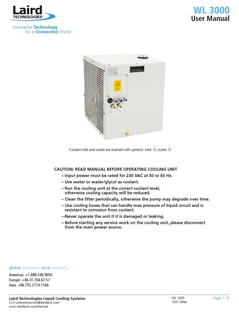
Other Laird Accessories manuals

Laird
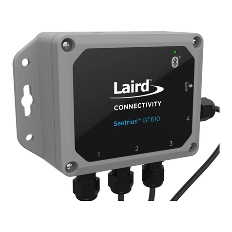
Laird Sentrius BT610 User manual

Laird
Laird Sentrius RS1 Series User manual

Laird
Laird Sentrius RS1 Series User manual

Laird
Laird Outdoor Cooler Series Installation instructions

Laird
Laird Outdoor Cooler Series Installation instructions

Laird
Laird Sentrius BT610 User manual

Laird
Laird WL 3000 User manual

Laird
Laird Sentrius BT510 User manual

Laird
Laird AA-230 Series Installation instructions