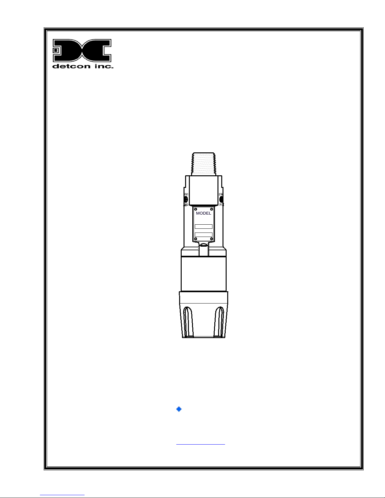
Detcon DM-100 Series User manual

Model DM-100
DM-100 Toxic Gas Sensors
DM-100 O2 Deficiency Sensors
DETCON, INC.
RANGE
100 PPM
DM-100
GAS
H2S
Operator’s Installation and Instruction Manual
Covers all Model DM-100 Sensors
DETCON, Inc.
4055 Technology Forest Blvd,
The Woodlands, Texas 77381
Ph.281.367.4100 / Fax 281.298.2868
www.detcon.com
June 08, 2018 • Document #3604 • Revision 3.5

Model DM-100
Model DM-100 ii
This page left intentionally blank

Model DM-100
Model DM-100 iii
Table of Contents
1. Introduction ..................................................................................................................................................1
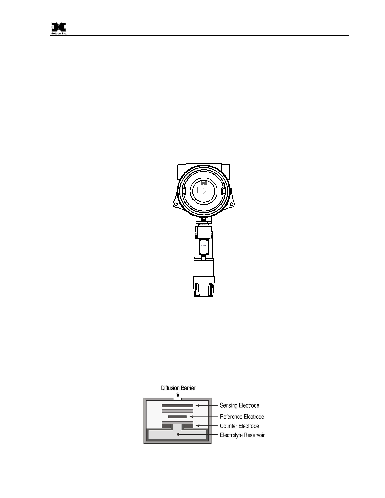
1.1 Description.......................................................................................................................................... 1
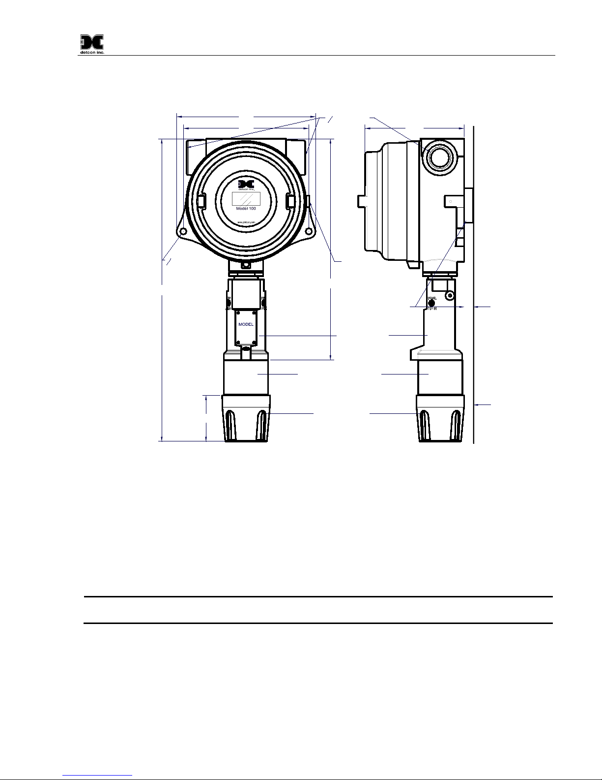
1.2 Modular Mechanical Design............................................................................................................... 2
1.3 Model 100 Standard Terminal Board (Optional)................................................................................ 4
1.4 DM-100 Display Terminal Board (Optional) ..................................................................................... 4
1.5 DM-100 Series Display (Optional)..................................................................................................... 5
1.6 Wireless Transceiver and Battery Pack (Optional)............................................................................. 5
2. Installation....................................................................................................................................................6
2.1 Hazardous Locations Installation Guidelines for Safe Use................................................................. 6
2.2 Sensor Placement................................................................................................................................ 7
2.3 Sensor Contaminants and Interference ............................................................................................... 8
2.4 Sensor Mounting................................................................................................................................. 8
2.5 Electrical Installation.......................................................................................................................... 9
2.6 Field Wiring...................................................................................................................................... 10
2.6.1 DM-100 Display Terminal Board Settings................................................................................... 11
2.7 Initial Start Up................................................................................................................................... 11
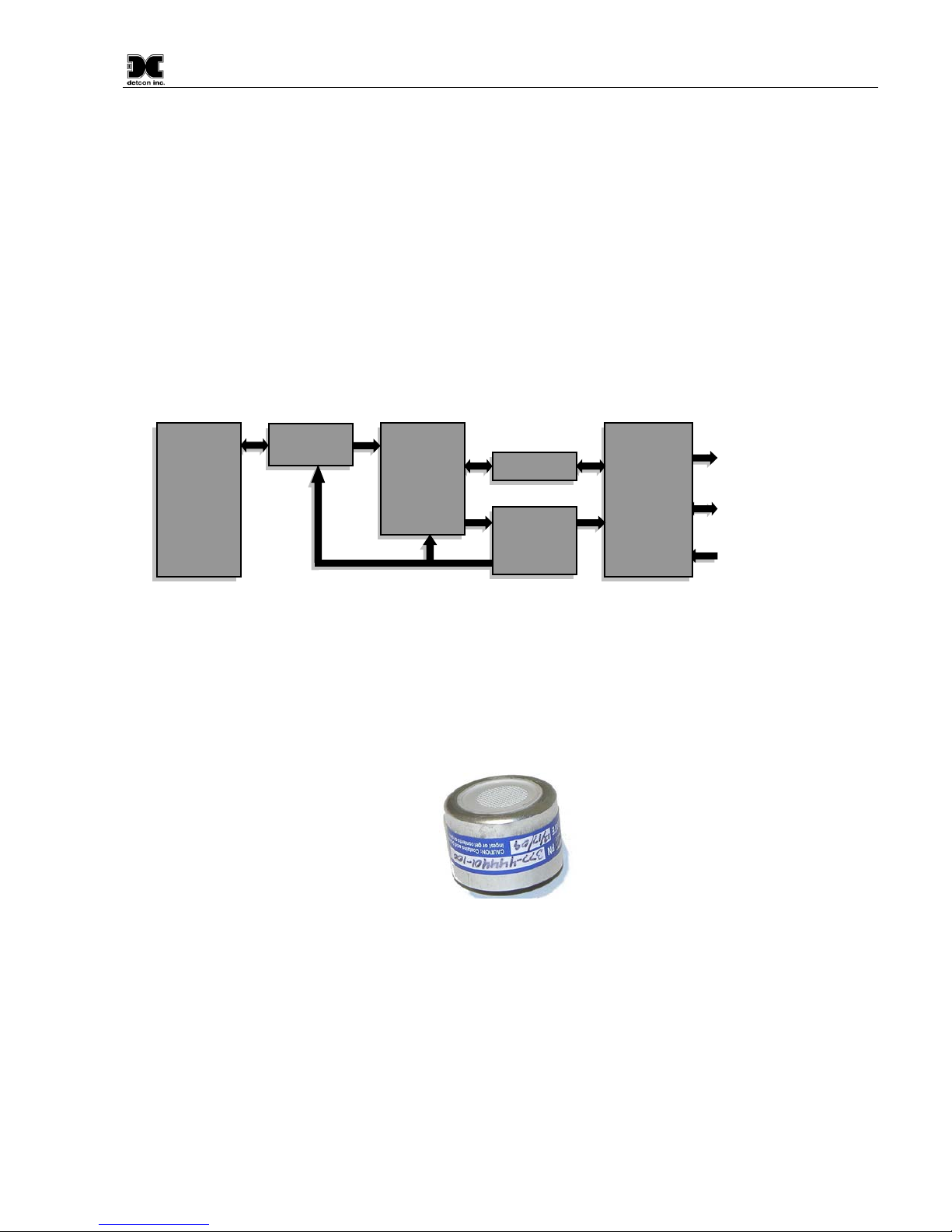
2.7.1 Toxic Gas Sensors........................................................................................................................ 11
2.7.2 O2Deficiency Sensors.................................................................................................................. 13
3. Operation....................................................................................................................................................14
3.1 Normal Operation ............................................................................................................................. 14
3.2 Auto Span Level Adjustment............................................................................................................ 14
3.3 Calibration ........................................................................................................................................ 15
3.3.1 Zero Calibration............................................................................................................................ 15
3.3.2 Span Calibration........................................................................................................................... 17
3.4 Fault Diagnostic/Failsafe Feature ..................................................................................................... 19
4. Service and Maintenance............................................................................................................................20
4.1 Replacement of Plug-in Sensor......................................................................................................... 20
4.2 Replacement of ITM......................................................................................................................... 21
4.3 Replacement of the Model 100 Terminal Board............................................................................... 21
5. Troubleshooting Guide...............................................................................................................................23
5.1 Smart Display Error Codes............................................................................................................... 25
6. Customer Support and Service Policy........................................................................................................26
7. DM-100 Sensor Warranty ..........................................................................................................................27
8. Appendix ....................................................................................................................................................28
8.1 Specifications.................................................................................................................................... 28
8.2 Sensor Specific Data......................................................................................................................... 29
8.3 Interference Table............................................................................................................................. 31
8.4 Proper Application and Maintenance of Acrylonitrile Sensor.......................................................... 37
8.5 Intrinsically Safe Installation Guidelines, Control Drawing #3993.................................................. 38
8.6 Spare Parts, Sensor Accessories, Calibration Equipment................................................................. 39
8.7 Revision Log..................................................................................................................................... 40

Model DM-100
Model DM-100 iv
Table of Figures
Figure 1 Sensor Assembly with Optional J-Box and LED Display ..................................................................... 1
Figure 2 Construction of Electrochemical Toxic Sensor...................................................................................... 1
Figure 3 Construction of Galvanic Cell................................................................................................................ 2
Figure 4 Sensor Assembly Breakaway................................................................................................................. 2
Figure 5 Functional Block Diagram..................................................................................................................... 3
Figure 6 Plug-in Sensor........................................................................................................................................ 3
Figure 7 DM Standard Terminal Board................................................................................................................ 4
Figure 8 Model 100 Display Terminal Board ...................................................................................................... 4
Figure 9 Model 100 Series Display...................................................................................................................... 5
Figure 10 Approval Label .................................................................................................................................... 6
Figure 11 Typical DM-100 Sensor Assembly and Mounting Dimensions.......................................................... 9
Figure 12 Typical Installation ............................................................................................................................ 10
Figure 13 Magnetic Programming Tool............................................................................................................. 14
Figure 14 Magnetic Programming Switches...................................................................................................... 14
Figure 15 Control Drawing #3993 ..................................................................................................................... 38
List of Tables
Table 1 Terminal Board Connectors .................................................................................................................... 5
Table 2 Model 100 Terminal Board Jumper ...................................................................................................... 11
Table 3 Sensor Specific Data ............................................................................................................................. 29
Table 4 Interfering Gases ................................................................................................................................... 31
Table 5 Cross Interference Table ....................................................................................................................... 32
Shipping Address: 4055 Technology Forest Blvd, The Woodlands, Texas 77381
Mailing Address: P.O. Box 8067, The Woodlands Texas 77387-8067
Phone: 888.367.4286, 281.367.4100 • Fax: 281.292.2860 • www.detcon.com • sales@detcon.com

Model DM-100
DM-100 Instruction Manual Rev. 3.5 Page 1 of 41
1. Introduction
1.1 Description
Detcon Model DM-100 toxic gas and O2deficiency sensors are non-intrusive 4-20mA loop powered sensors
designed to detect and monitor a wide range of toxic gases in the air. Ranges of detection for toxic gases are 0-
1ppm up to 0-10,000ppm; typical ranges of detection are 0-10ppm, 0-25ppm, 0-50ppm and 0-100ppm. Ranges
for O2deficiency are 0-1% up to 0-25% by volume.
The basic sensor assembly consists of an electrochemical fuel cell mounted in Intrinsically Safe stainless steel
housing and includes a Splash Guard Cal Adapter. Optionally, the sensor can be installed on an explosion
proof junction box with a Model 100 Terminal Board and may include a Model 100 Loop Powered LED
display. Other options are available, contact Detcon for more information.
DETCON, INC.
H2S
100 PPM
DM-100
Model 100
Figure 1 Sensor Assembly with Optional J-Box and LED Display
Electrochemical Sensor Technology
The DM-100 toxic gas sensors are based on electrochemical cells. Each cell consists of three electrodes
embedded in an electrolyte solution all housed beneath a diffusion membrane. Sensitivity to specific target
gases is achieved by varying composition of any combination of the sensor components. Good specificity is
achieved in each sensor type. The cells are diffusion limited via small capillary barriers resulting in a long
service life of up to three or more years. The electrochemical cell is packaged as a field replaceable plug-in
sensor.
Figure 2 Construction of Electrochemical Toxic Sensor

Model DM-100
DM-100 Instruction Manual Rev. 3.5 Page 2 of 41
The DM-100 O2deficiency sensor technology is a two electrode galvanic metal air battery type cell, which is
housed as a field replaceable intelligent plug-in sensor. The cell is diffusion limited and functions as a direct
current generator proportional to the amount of oxygen adsorption. The sensors are temperature compensated
and show good accuracy and stability over the operating temperature range of -20° to 50°C (-4° to +122° F).
The sensor is warranted for two years and has an expected service life of up to 2.5 years in ambient air at
20.9% oxygen.
Figure 3 Construction of Galvanic Cell
1.2 Modular Mechanical Design
The Model DM-100 Sensor Assembly is completely modular and is made up of four parts (Figure 4):
1. DM-100 Intelligent Transmitter Module (ITM)
2. Intelligent Plug-in Sensor (varies by gas type and range)
3. 100 Series Bottom Housing Assembly (H2S assemblies use 100 Series Bottom Housing Assembly
with Integral Filter)
4. Splash Guard.
O-Ring
100 Series Bottom
Housing Assembly Plug-in
Replaceable
Sensor Interconnect
Wires
Housing Bottom
Locking Screw Intelligent Transmitter Module (ITM)
Micro-processor controlled circuit
encapsulated in an Explosion proof
housing.
Magnetic
Programming
Switches
Splash Guard
DETCON, INC.
H2S
100 PPM
DM-100
34
" NPT Locking Nut
Figure 4 Sensor Assembly Breakaway
NOTE
All metal components are constructed from electro polished 316 Stainless Steel in order to
maximize corrosion resistance in harsh environments.

Model DM-100
DM-100 Instruction Manual Rev. 3.5 Page 3 of 41
DM-100 Intelligent Transmitter Module
The Transmitter Module is a microprocessor-based package that is attached to the explosion proof junction
box.
Circuit functions include;
•an intrinsically safe barrier,
•on-board power supply,
•microprocessor,
•magnetic programming switches,
•and a linear 4-20mA DC output.
Magnetic program switches located on either side of the ITM are activated via a hand-held magnetic
programming tool, thus allowing non-intrusive operator interface with the Transmitter Module. Electrical
classifications are Class I, Division 1, Groups A, B, C, and D.
Figure 5 Functional Block Diagram
Field Replaceable Sensor
The Detcon family of electrochemical gas sensors is field proven, plug-in sensors with over-sized gold-plated
connections that eliminate corrosion problems. The sensor can be accessed and replaced in the field easily by
releasing the locking screw and unthreading the Splash Guard Adapter. Detconꞌs family of toxic sensors has a
long shelf life and is supported by an industry-leading warranty (Section 7).
Figure 6 Plug-in Sensor
I/O
Circuit
Protection
RS-485 Port
Analog 4-20mA Out
Power In
RS-485
4-20mA
Loop
Power
Micro-
Processor
Intrinsically
Safe Barrier
Plug-In
Sensor

Model DM-100
DM-100 Instruction Manual Rev. 3.5 Page 4 of 41
1.3 Model 100 Standard Terminal Board (Optional)
If the sensor is ordered with an explosion proof condulet/junction box, the sensor will come with the Model
100 Standard Terminal Board mounted in the J-Box (Figure 7). This terminal board affords the user easy plug-
in connectors for use in wiring the unit during installation, and convenient test points for measuring the
milliamp (mA) output.
RED
GREEN
BLUE
WHITE
V+
mA
Customer
Wiring
Sensor Wiring
Figure 7 DM Standard Terminal Board
The standard terminal board provides an easy Digital Volt Meter (DVM) connection for reading the mA output
from the sensor. Two test points (TP1 and TP2) provide a connection across a 10Ω resistor that develops a
10mV voltage drop per 1mA output. Thus a reading of 40mV on a DVM equals 4mA of current. This is an
alternative method to reading the mA output of the sensor for assemblies that do not include the DM-100
Series Display option. Refer to Section 2.6, Field Wiring for more information about the setup of the DM-100
Terminal Board.
1.4 DM-100 Display Terminal Board (Optional)
If the unit is ordered with the optional display or a battery pack (wireless configurations) the unit comes with
the DM-100 Display Terminal Board mounted in the J-Box (Figure 8).
J6
J7
J4
J1
J5
J8
L9
J2
AIN1
W/BK
W/BN
W/BU
W/GN
W/V
WIRELESS
AIN2
MA
GND
PWR
POWER IN
( SOLAR)
WIRELESS
PROGRAM
B
A
GND
24V
MODBUS OUT
( WIRELESS)
24V
GND
A
B
MODBUS IN
24V
GND
A
B
SENSOR
PWR
GND
SCL
SDA
SP1
SP2
DISPLAY
JP1
SW2
SW1
TERM
PROGRAM
POWER
mA
RED
BLACK
BLUE
WHITE
Customer Wiring
Figure 8 Model 100 Display Terminal Board

Model DM-100
DM-100 Instruction Manual Rev. 3.5 Page 5 of 41
This terminal board includes connectors for the following:
Table 1 Terminal Board Connectors
Terminal Connector Purpose
J1
4-Pin Connector
Modbus Out (Wireless Transceiver Option)
J2
6-Pin Header
Wireless Transceiver Programming Header
J3
6-Beau Connector
Battery operation or display interface dependent on sensor configuration
J4
4-Pin Connector
Modbus In
J5
6-Pin Connector
Display interface with battery/wireless configurations
J6
4-Pin Connector
Sensor connections
J7
4-Pin Connector
Auxiliary power in and mA out
J8
6-Pin Connector
Wireless Transceiver
J9
5-Pin Header
Terminal Board Programming
The Model 100 Display Terminal Board does not provide test points for measuring the milliamp (mA) output.
The mA output is available at J7.
NOTE
Install JP1 jumper on pins 1 and 2 if a battery pack is used. Install JP1 on pins 2 and 3 if
battery is not used.
1.5 DM-100 Series Display (Optional)
The DM-100 Series Display is a 4-digit LED display that provides a direct display of the sensor readings. In
units that are ordered with the optional display, the display is mounted directly onto the J3 Beau connector of
the Display Terminal Board so the display can be easily seen through the J-box window. The display
automatically identifies the ITM, the sensor type, and range. This factory installed option must be ordered with
the sensor assembly.
Figure 9 Model 100 Series Display
1.6 Wireless Transceiver and Battery Pack (Optional)
The DM-100 has the option to operate on a wireless network with the addition of a wireless transceiver and
battery pack. These options allow the sensor to be remotely mounted without the need for cables. These
options are factory installed. Contact Detcon for more information on these options.

Model DM-100
DM-100 Instruction Manual Rev. 3.5 Page 6 of 41
2. Installation
2.1 Hazardous Locations Installation Guidelines for Safe Use
1. Install the sensor only in areas with classifications matching the approval label. Follow all warnings
listed on the label.
Figure 10 Approval Label
2. For intrinsically safe Ex ia installations, follow the intrinsically safe installation guidelines shown in
control drawing #3993, Section 8.5.
3. For non-intrinsically safe Ex mb [ib] installations, ensure that the sensor is properly threaded into a
suitable explosion-proof rated junction box with a downward pointing female 3/4" NPT threaded
connection. The sensor should be threaded at least 5 full turns until tight, with the locking screw
facing forward. Avoid use of Teflon Tape, or any type of non-conductive pipe thread coating on the
NPT threaded connection.
4. A good ground connection should be verified between the sensor’s metal enclosure and the junction
box. If a good ground connection is not made, the sensor can be grounded to the junction box using
the sensor’s external ground lug. Verify a good ground connection between the junction box and earth
ground.
5. Proper precautions should be taken during installation and maintenance to avoid the build-up of static
charge on the plastic components of the sensor (Splash Guard and Splash Guard adapter).
6. All input circuits of the DM-100 must be connected to current limiting devices (e.g. Fuses of 1500
amp breaking capacity) to ensure that the maximum input current does not exceed 62mA.
7. Do not substitute components. Substitution of components may impair the intrinsic safety rating.
8. Do not operate the sensor outside of the stated operating temperature limits.
9. Do not operate the sensor outside the stated operating limits for voltage supply.
10. These sensors meet ATEX standards EN60079-0, EN60079-18 and EN60079-11.
11. These sensors have a maximum safe location voltage of Um=60V.
12. These sensors pass dielectric strength of 500VRMS between circuit and enclosure for a minimum of 1
minute at a maximum test current of 5mA.

Model DM-100
DM-100 Instruction Manual Rev. 3.5 Page 7 of 41
13. The DM-100 may be used as an oxygen deficiency sensor; the DM-100 must not be used for detecting
oxygen concentrations expected to be greater than 21%.
14. The DM-100 must only use gas sensor cell models 371-xxxxxx-xxx (Table 5, Section 8.1). No other
gas sensor cells shall be used.
2.2 Sensor Placement
Sensor location is critical to the overall safe performance of the product. Five factors play an important role in
selection of sensor locations:
1. Density of the gas to be detected
2. Most probable leak sources within the industrial process
3. Ventilation or prevailing wind conditions
4. Personnel exposure
5. Maintenance access
Density
Placement of sensors relative to the density of the target gas is such that sensors for the detection of heavier
than air gases should be located within 4 feet of grade as these heavy gases will tend to settle in low lying
areas. For gases lighter than air, sensor placement should be 4 to 8 feet above grade in open areas or in pitched
areas of enclosed spaces.
Leak Sources
The most probable leak sources within an industrial process include flanges, valves, and tubing connections of
the sealed type where seals may either fail or wear. Other leak sources are best determined by facility
engineers with experience in similar processes.
Ventilation
Normal ventilation or prevailing wind conditions can dictate efficient location of gas sensors in a manner
where the migration of gas clouds is quickly detected.
Personnel Exposure
The undetected migration of gas clouds should not be allowed to approach concentrated personnel areas such
as control rooms, maintenance or warehouse buildings. A more general and applicable thought toward
selecting sensor location is combining leak source and perimeter protection in the best possible configuration.
Maintenance Access
Consideration should be given to providing easy access for maintenance personnel and the consequences of
close proximity to contaminants that may foul the sensor prematurely.
NOTE
In all installations the gas sensor should point straight down (Figure 12). Improper sensor
orientation may result in false readings and permanent sensor damage.
Additional Placement Considerations
The sensor should not be positioned where it may be sprayed or coated with surface contaminating substances.
Painting sensor assemblies is prohibited.

Model DM-100
DM-100 Instruction Manual Rev. 3.5 Page 8 of 41
Although the sensor is designed to be RFI resistant, it should not be mounted in close proximity to high-
powered radio transmitters or similar RFI generating equipment.
When possible mount in an area void of high wind, accumulating dust, rain, or splashing from hose spray,
direct steam releases, and continuous vibration. If the sensor cannot be mounted away from these conditions
then ensure the Detcon Harsh Location Dust Guard accessory is used.
Do not mount in locations where temperatures will exceed the operating temperature limits of the sensor.
Where direct sunlight leads to exceeding the high temperature-operating limit, use a sunshade to help reduce
temperature.
2.3 Sensor Contaminants and Interference
Electrochemical toxic gas may be adversely affected by exposure to other airborne gases. Depending on the
cross-sensitivity relationship, there may be a positive or negative impact on the reading.
The most commonly present gases that potentially cause interference problems are listed in Table 4,
Interfering Gases and Table 5, Cross Interference Table (Section 8.3, Interference Table).
The presence of cross-interference gases in an area does not preclude the use of this sensor technology. The
sensor could experience a false high or false low reading should exposure occur.
Cross-Interference Data Table
The gases typically found in industrial environments that may cause a cross-interference response on Detcon
toxic gas sensors are listed in Table 5 (Section 8.3, Interference Table). Review Table 5 for the correct gas and
then scan across the list for possible interference gases. Determine the magnitude of cross-interference that
may occur.
2.4 Sensor Mounting
The DM-100 should be vertically oriented so that the sensor points straight downward. The explosion-proof
enclosure or junction box is typically mounted on a wall or pole (Figure 11). Detcon provides a selection of
standard junction boxes in both Aluminum and Stainless Steel.
NOTE
If wall mounting without a mounting plate, make sure to use at least 0.5" spacers
underneath the J-Box’s 1/4" mounting holes to move the wireless sensor assembly away
from the wall and allow access clearance to the sensor assembly.
NOTE
Do not use Teflon Tape or any other type of Pipe Thread material on the 3/
4
" threads unless
the sensor is mounted in a severe or harsh environment. Metal-on-metal contact must be
maintained to provide a solid electrical ground path. If Teflon Tape is used the Sensor must
be externally grounded using a ground strap.

Model DM-100
DM-100 Instruction Manual Rev. 3.5 Page 9 of 41
When mounting on a pole, secure the Junction Box to a suitable mounting plate and attach the mounting plate
to the pole using U-Bolts. (Pole-Mounting brackets for Detcon Junction Box’s are available separately.)
8-32 tapped
ground point
4.35"
34
NPT Ports
6.1"
5.5"
14
" mounting holes
Wall (or other
mounting surface)
Splash Guard Adapter
Splash Guard
2"
DETCON, INC.
H2S
100 PPM
DM-100 ITM Assembly
13.75" Typ. 9.625" Typ.
Use spacers to move
sensor assembly away
from wall at least 0.5".
Spacer
Figure 11 Typical DM-100 Sensor Assembly and Mounting Dimensions
2.5 Electrical Installation
The Sensor Assembly should be installed in accordance with local electrical codes. The sensor assemblies are
CSA/NRTL approved (US and Canada) for Class I, Division 1, Groups A, B, C, & D area classifications, and
are ATEX Approved for Class I, Zone 1, Group IIC area classifications.
Proper electrical installation of the gas sensor is critical for conformance to Electrical Codes and to avoid
damage due to water leakage. Refer to Figure 8 and Figure 12 for proper electrical installation.
NOTE
If a conduit run exits the secondary port, repeat the installation technique shown in
Figure 12.
In Figure 12, the drain allows H2O condensation inside the conduit run to safely drain away from the sensor
assembly. The electrical seal fitting is required to meet the National Electrical Code per NEC Article 500-3d
(or Canadian Electrical Code Handbook, Part 1, Section 18-154). Requirements for locations of electrical seals
are covered under NEC Article 501-5. Electrical seals act as a secondary seal to prevent water from entering
the wiring terminal enclosure. However, they are not designed to provide an absolute watertight seal,
especially when used in the vertical orientation.

Model DM-100
DM-100 Instruction Manual Rev. 3.5 Page 10 of 41
NOTE
For products utilizing the aluminum junction box option, the conduit seal shall be placed at
the entry to the junction box (see Figure 12 as an example). For products utilizing the
stainless steel ju
nction box option, the conduit seal shall be placed within 18" of the
enclosure. Crouse Hinds type EYS2, EYD2 or equivalent are suitable for this purpose.
NOTE
The Detcon Warranty does not cover water damage resulting from water leaking into the
enclosure.
Drain
Conduit
"T" EYS Seal Fitting
DETCON, INC.
H2S
100 PPM
DM-100
Model 100
Figure 12 Typical Installation
NOTE
Any unused ports should be blocked with suitable 3/
4
" male NPT plugs. Detcon supplies one
3/4" NPT male plug with each J-box enclosure. If connections are other than 3/4" NPT, use
an appropriate male plug of like construction material.
2.6 Field Wiring
Detcon Model DM-100 sensor assemblies require two conductor connections between power supplies and host
electronic controller’s 4-20mA input. Wiring designations are PWR and mA (sensor signal).
NOTE
Shielded cable is required for installations where cable trays or conduit runs include high
voltage lines or other possible sources of induced interference. Separate conduit runs are
highly recommended in these cases.
NOTE
The supply of power should be from an isolated source with over-current protection.

Model DM-100
DM-100 Instruction Manual Rev. 3.5 Page 11 of 41
Terminal Connections – with Junction Box Option
CAUTION Do not apply System power to the sensor until all wiring is properly terminated.
Refer to Section 2.7, Initial Start Up.
1. Remove the junction box cover.
2. If the sensor has the Display option installed, unplug the display from the terminal board by pulling the
display out of the junction box. The display option plugs directly into the terminal board’s Beau
Connector.
3. Observing correct polarity, terminate the 2-conductor power and 4-20mA field wiring (+ and mA) at the
terminal board connector J1 (4-20mA Out) on the Standard Terminal Board shown in Figure 7, or J7
(PWR and MA) on the Display Terminal Board shown in Figure 8.
4. Trim and cap all exposed wire leads if they are not permanently landed in the terminal board.
5. The sensor should be connected to J2, labeled SENSOR on the Standard Terminal Board, and J6, labeled
SENSOR, on the Display Terminal Board. On the Standard Terminal Board, the wiring from the sensor
should match the silkscreen on the terminal board: R–Red, BK–Black, GN-Green, BU–Blue, and W–
White. On the Display Terminal Board the wiring should be: Red-PWR, Black-GND, White–A, Blue–B
(Green is not connected).
6. On the Display Terminal Board other connectors are provided for factory installed options. The options
ordered will dictate if, and what connectors are used. The display option is plugged into the Beau
connector (J3) for a DM-100 with just the display option added. Other options are covered in the
associated manual for those options.
7. If a display was removed in Step 2, re-install the display by plugging it back into the terminal board.
8. Replace the junction box cover after initial startup.
NOTE
A 6-32 or 8-32 threaded exterior ground point is provided on most junction boxes for an
external ground. If the Sensor Assembly is not mechanically grounded, an external ground
strap must be used to ensure that the sensor is electrically grounded.
2.6.1 DM-100 Display Terminal Board Settings
The Model 100 Display Terminal Board contains a jumper that must be configured properly for the board to
operate correctly. The jumper is normally configured at the factory and should not be changed. Misplacement
of the jumper may cause the sensor to become inoperative.
Table 2 Model 100 Terminal Board Jumper
JP1
1-2 – Battery installed
2-3 – Display only
2.7 Initial Start Up
2.7.1 Toxic Gas Sensors
Upon completion of all mechanical mounting and termination of all field wiring, apply system power in the
range of 11-26VDC (24VDC typical) and observe the following normal conditions:

Model DM-100
DM-100 Instruction Manual Rev. 3.5 Page 12 of 41
1. If the Loop Powered Display option is installed, the display should read 0.0 upon power up. If a Loop
Powered Display is not installed on the sensor, set a DVM to measure millivolts, and connect it across
TP1 and TP2 on the terminal board. The DVM will read the voltage drop across a 10Ω resistor. The
resistor develops a 10mV voltage drop per 1mA of current. Thus a reading of 40mV on a DVM equals
4mA of current.
2. A temporary upscale reading may occur as the sensor stabilizes. This upscale reading will decrease to
"0" ppm (40mV on the DVM) within 1 to 2 minutes of power-up, assuming there is no gas in the area
of the sensor.
NOTE
The 4-20mA signal is held constant at 4mA for the first two minutes after power up.
3. Sensors cells that use a bias voltage require a longer time to stabilize. This can vary between 1 and 24
hours depending on the sensor type and range. Biased sensors include NH3, NO, HCl, and VOC gases
(ethylene oxide, ethylene, methanol, formaldehyde….etc).
Initial Operational Tests
After a warm up period of 1 hour (or when zero has stabilized), the sensor should be checked to verify
sensitivity to the target gas.
Material Requirements
•Detcon PN 613-120000-700 700 Series Splash Guard with integral Cal Port and Calibration Wind
Guard (P/N 943-000000-000) -OR-
•Detcon PN 943-000006-132 Threaded Calibration Adapter - OR -
•Detcon PN 943-01747-T05 Teflon Calibration Adapter for highly reactive gases
•Detcon Span Gas; 50% of range target gas in balance N2 or Air at fixed flow rate between
200-500cc/min (500cc/min is preferred)
•DVM (if a loop powered display is not installed)
NOTE
Calibration gas generators using perm tubes or electrochemical sources may be used in
place of span gas cylinders.
NOTE
The cover of the junction box will need to be removed if there is not a loop powered
display. The area may need to be de-classified.
1. If the sensor has a loop power display installed, the display should read "0". If a DVM is used to
measure the 4-20mA output, set the DVM to measure millivolts and connect the leads across TP1 and
TP2 on the terminal board. The DVM should read 40±2mV.
2. Attach the calibration adapter to the Splash Guard adapter or connect tubing to integral cal port. It is
recommended that the Wind Guard (PN 943-000000-000) in installed over the Splash Guard during
calibration. Apply the test gas at a controlled flow rate of 200-500cc/min (500cc/min is the
recommended flow). If the sensor has a loop power display attached the reading should increase to
50% of full range (if the range is 100, the display should read 50). Observe that the DVM increases to
a level near that of the applied calibration gas value. Typically this would be 50% of full range, a
reading of 120±2mV (12mA).
3. Remove test gas and observe that, if the sensor has a loop power display installed, the display
decreases to "0". If a DVM is used the DVM reading should decrease back to 40mV (4mA).

Model DM-100
DM-100 Instruction Manual Rev. 3.5 Page 13 of 41
4. If a calibration adapter was used during these tests, remove them from the unit, and re-install the
Splash Guard. If the wind guard was used, remove the wind guard.
Initial operational tests are complete. DM-100 toxic gas sensors are factory calibrated prior to shipment, and
should not require significant adjustment on start up. However, it is recommended that a complete calibration
test and adjustment be performed 16 to 24 hours after power-up. Refer to zero and span calibration instructions
in Section 3.3, Calibration.
2.7.2 O2Deficiency Sensors
Upon completion of all mechanical mounting and termination of all field wiring, apply system power in the
range of 11-30VDC (24VDC typical) and observe the following normal conditions:
If the sensor has a loop power display installed, the display should read close to 20.9%. If a DVM is used to
measure the 4-20mA output, set the DVM to measure millivolts and connect the leads across TP1 and TP2 on
the terminal board. The DVM should read 173.7±2mV.
The reading should stabilize within 1 to 2 minutes of power-up (assuming a ‘normal’ ambient O2
concentration).
Initial Operational Tests
After a warm-up period of 5 minutes the sensor should be checked to verify response to O2deficiency.
Material Requirements
•Detcon PN 613-120000-700 700 Series Splash Guard with integral Cal Port and Calibration Wind
Guard (P/N 943-000000-000) -OR-
•Detcon PN 943-000006-132 Threaded Calibration Adapter - OR -
•Detcon PN 943-01747-T05 Teflon Calibration Adapter for highly reactive gases
•Detcon Zero Gas: 100% N2 at fixed flow rate of 200-500cc/min
•DVM (if a loop powered display is not installed)
NOTE
The cover of the junction box will need to be removed if there is not a loop powered
display. The area may need to be de-classified.
1. Attach the calibration adapter to the threaded sensor housing or connect tubing to the integral cal port.
Apply the test gas at a controlled flow rate of 200-500cc/min (500cc/min is the recommended flow).
2. If the sensor has a loop power display installed, the display reading should drop to "0". If a DVM is
used to measure the 4-20mA output, set the DVM to measure millivolts and connect the leads across
TP1 and TP2 on the terminal board. The DVM should read 40±2mV.
3. Remove test gas and calibration adapter. If the sensor has a loop power display installed, the display
should return to a reading of 20.9%. The DVM should return to a reading of 173.7mV (17.37mA).
Initial operational tests are complete. DM-100 O2deficiency sensors are factory calibrated prior to shipment,
and should not require significant adjustment on start up. A complete calibration test and adjustment should be
performed 16 to 24 hours after power-up. Refer to zero and span calibration instructions in Section 3.3,
Calibration.

Model DM-100
DM-100 Instruction Manual Rev. 3.5 Page 14 of 41
3. Operation
The Operator Interface of the Model 100 Series gas sensors is accomplished via two internal magnetic
switches located on the left and the right of the sensor (Figure 14). The two switches, labeled PGM1 and
PGM2, allow for complete calibration of the sensor. The addition of the Loop Powered Display allows the
ability to calibrate the sensor without the need to de-classify the area or the use of hot permits.
Figure 13 Magnetic Programming Tool
The magnetic programming tool (Figure 13) is used to operate the magnetic switches. Switch action is defined
as momentary contact and 3-second hold. Hold time is defined as the time from the point when the magnet is
placed in close proximity with the switch. For momentary contact the programming magnet is briefly held
over a switch location. The location of PGM1 and PGM2 are shown in Figure 14.
DETCON, INC.
H2S
100 PPM
DM-100
Program 1 Program 2
Figure 14 Magnetic Programming Switches
3.1 Normal Operation
In normal operation, the mA output will be the current sensor reading. In normal operation, the 4-20mA
current output linearity corresponds with the full-scale range. If the DM-100 Display option is added to the
sensor, the display continuously shows the current sensor reading in ppm or % by volume, which will
normally appear as "0". If the sensor is actively experiencing any diagnostic faults, the mA output will be
taken to 1.2mA to designate a fault to the controller. The DM-100 Display will display an error code to signify
a fault. Error codes are noted by Fxx, where F is Fault and xx is an error code. Error codes are defined in
Section 5, Troubleshooting Guide .
3.2 Auto Span Level Adjustment
This procedure can only be achieved if the unit has a display.
1. In normal operation, hold the programming magnet over PGM2 for a minimum of 3 seconds to set the
Auto span level.

Model DM-100
DM-100 Instruction Manual Rev. 3.5 Page 15 of 41
2. SET AUTO SPAN will scroll across the display to indicate entry into the routine.
3. When adjustments can be made, the display will scroll ADJUST AUTO SPAN. Swipe PGM2 to
adjust the AutoSpan Level up. Swipe PGM1 to adjust it down.
4. If no action is taken within 5 seconds, the display will scroll AUTO SPAN NOT SAVED to indicate
a value was not saved. The unit will then return to normal operation.
5. If changes are made, the display will reflect the adjustments.
6. A 2 second hold on PGM1 or PGM2 will save the level. The display will scroll AUTO SPAN
SAVED to indicate that the value was saved and the unit will return to normal operation.
7. If no hold is placed on PGM1 or PGM2, the level will revert to the previous value. The display will
scroll AUTO SPAN NOT SAVED to indicate that the value was not saved and the unit will return to
normal operation.
3.3 Calibration
Zero and span calibration should be performed on a routine basis (quarterly minimum) to ensure reliable
performance. If a sensor has been exposed to any de-sensitizing gases, or to very high over-range combustible
gas levels, re-calibration should be considered. Unless otherwise specified, span adjustment is recommended at
50% of the full scale range.
3.3.1 Zero Calibration
The zero calibration is used to zero the sensor. Zero calibration should be performed periodically or as
required. Zero calibration should be considered after periods of over-range target gas exposure. Local ambient
air can be used to zero calibrate a toxic gas sensor as long as it can be confirmed that it contains no target or
interference gases. If this cannot be confirmed then a zero air or N2cylinder should be used. Pure N2must be
used for zero calibration of the O2deficiency sensors.
Material Requirements:
•Detcon PN 327-000000-000 Programming Magnet
•Detcon PN 613-120000-700 700 Series Splash Guard with integral Cal Port and Calibration Wind
Guard (P/N 943-000000-000) -OR-
•Detcon PN 943-000006-132 Threaded Calibration Adapter - OR -
•Detcon PN 943-01747-T05 Teflon Calibration Adapter for highly reactive gases
•Detcon PN 942-001123-000 Zero Air cal gas (or use ambient air if no target gas is present).
•Detcon PN 942-640023-100 Nitrogen 99.99%
•DVM (if a loop powered display is not installed)
NOTE 1:
The zero gas source may be zero air or N
2
for toxic sensors, but must be pure N
2
(99.99%)
for O2deficiency sensors.
NOTE 2:
The Calibration Wind Guard must be used when the Splashguard Adapter with integral Cal
Port is used. Failure to use the Calibration Wind Guard may result in an inaccurate
AutoZero calibration.
NOTE 3:
The cover of the junction box will need to be removed if there is not a loop powered
display. The area may need to be de-classified.

Model DM-100
DM-100 Instruction Manual Rev. 3.5 Page 16 of 41
3.3.1.1 Display Not Installed
1. If a DM-100 Display is not installed on the sensor, set a DVM to measure millivolts, and connect it
across TP1 and TP2 on the terminal board. The DVM will read the voltage drop across a 10Ω resistor.
The resistor develops a 10mV voltage drop per 1mA of current. Thus a reading of 40mV on a DVM
equals 4mA of current.
2. For toxic sensors, if the ambient air is known to contain no target gas content, then it can be used for
zero calibration. If a zero gas cal cylinder is going to be used, attach the calibration adapter and set
flow rate of 200-500cc/min (500cc/min is the recommended flow rate) and let the sensor purge for 1 to
2 minutes before zeroing the sensor. For O2deficiency sensors, apply N2at a set flow rate of
500cc/min for 3 to 5 minutes before zeroing the sensor.
NOTE:
For O2 deficiency sensors N2 (99.99%) MUST be applied at a flow rate of 500cc/min for
a time period of 3 to 5 minutes to successfully zero calibrate the sensor.
3. From Normal Operation, hold the programming magnet over PGM1 for 3 seconds. The reading will
dip momentarily to 2mA (20mV on the meter). The reading will then return to 4ma. (The ideal reading
for zero is 4.03mA or 40.3mV.)
4. Observe the reading for a minute or so to ensure that the reading does not drift.
5. If zero gas was used, remove the gas from the sensor.
3.3.1.2 With Display
1. For toxic sensors, if the ambient air is known to contain no target gas content, then it can be used for
zero calibration. If a zero gas cal cylinder is going to be used, attach the calibration adapter and set
flow rate of 200-500cc/min (500cc/min is the recommended flow rate) and let the sensor purge for 1 to
2 minutes before zeroing the sensor. For O2deficiency sensors, apply N2at a set flow rate of
500cc/min for 3 to 5 minutes before zeroing the sensor.
NOTE:
For O2 deficiency sensors N2 (99.99%) MUST be applied at a flow rate of 500cc/min for
a time period of 3 to 5 minutes to successfully zero calibrate the sensor.
2. From Normal Operation, hold the programming magnet over PGM1 for 3 seconds. The display will
scroll 1-ZERO…2-SPAN for 10 seconds.
NOTE
If no action is taken unit returns to normal operation after time expires, 10 seconds.
3. Hold PGM1 to start Auto Zero routine, ZERO IN PROGRESS… will scroll across the display. Output
current from the sensor will drop to 3.5mA.
4. Observe the reading for a minute or so to ensure that the reading does not drift.
5. If zero gas was used, remove the gas from the sensor.
This manual suits for next models
2
Table of contents
Other Detcon Accessories manuals

Detcon
Detcon MicroSafe DM-534C User manual

Detcon
Detcon CXT-IR User manual

Detcon
Detcon FP-524D User manual

Detcon
Detcon TP-524D User manual

Detcon
Detcon PI-700 User manual

Detcon
Detcon DM-500IS OLED Series User manual

Detcon
Detcon FP-700 User manual

Detcon
Detcon DM-700 User manual

Detcon
Detcon MicroSafe TP-524C User manual

Detcon
Detcon TP-700 User manual
Popular Accessories manuals by other brands

MaxAir Trampolines
MaxAir Trampolines 7' x 14' flybed tramp Installation instructions & user guide

HAEGER
HAEGER UB-070.001A User instructions

Schwaiger
Schwaiger HOME4YOU ZHS19 user manual

Keysight
Keysight 2050 Series user guide

Rice Lake
Rice Lake MSI-8000HD Technical manual

Milesight
Milesight LoRaWAN WS302 user guide