LA Audio Electronic C400 User manual

4 Channel
Auto Compressor
Operation Manual
April 2002

Page 2
This page has been left intentionally blank for your notes

Page 3
CONTENTS
1.0 OVERVIEW 4
2.0 DESCRIPTION OF CONTROLS 5-7
2.1 Bypass switch
2.2 Program switch
2.3 Threshold control
2.4 Ratio control
2.5 Auto-Manual switch
2.6 Hard-Soft Knee switch
2.7 Release control
2.8 Gain control
2.9 Gain Reduction meter
2.10 Link switch
3.0 EXTERNAL CONNECTIONS 8-9
3.1 Side Chain insert
3.2 Input
3.3 Output
3.4 Level switch
3.5 Power switch
3.6 Power inlet
4.0 INSTALLATION 10-11
4.1 Inspection and unpacking Phantom
4.2 Operating Environment +48V indicator
4.3 CE Standard and LVD Pad
4.4 Power Requirement Listen
5.0 WARRANTY 12
6.0 TECHNICAL SPECIFICATION 13
7.0 DIMENSIONS 14

Page 4
1.0 OVERVIEW
Main Features:
•4 channels of Auto compression
•Soft or hard knee compression slopes
•Fully variable Threshold, Ratio, Release and Gain
•Auto Attack/Release and Program Dependant Attack with manual Release modes
•Low frequency Program filter
•Side chain inserts
•Balanced Inputs-Outputs with +4dBu/10dBV switching
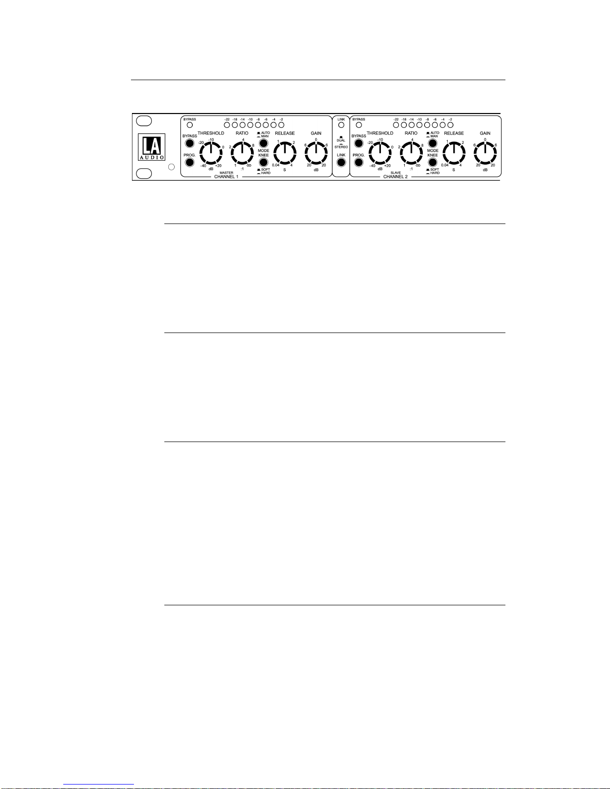
The C400 is a professional 4 channel compressor that can be operated as 4 separate
processors or linked as two independent stereo pairs. In Link mode, Channel 1 and 3
provide Master control and 'rms summing' is used to ensure that signals from both the
linked channels affect compression equally.
Each channel has fully variable controls for Threshold, Ratio, Release and Gain.
Compression slope can be switched between Hard or Soft knee, with Hard knee
providing tight control of compression Ratio and Soft knee a more progressive style of
compression.
Two Attack/Release modes are available; Auto Attack/Release or Program Dependant
Attack with manually adjustable Release. A low frequency Program filter can be switched
into the sidechain to reduce the effects of bass heavy material causing over compression.
Each channel also has a sidechain insert on TRS jack to allow connection of external
processing such as an equaliser.
Gain Reduction is displayed on an 8 segment LED bargraph. The Bypass and Link
switches also have led indicators.
All inputs and outputs are electronically balanced and can be switched between +4dBu
and -10dBV operating levels.
Page 5
2.0 DESCRIPTION OF CONTROLS
2.1 BYPASS switch
Pressing BYPASS cancels compression by removing the side chain voltage from
the voltage controlled amplifier (VCA). The Input-Output and level change
circuitry remain in the signal path.
The BYPASS led lights when the compressor is Bypassed.
2.2 PROG. switch
The PROGRAM switch inserts a low-cut filter into the side chain to remove the
bass content of the program material which can cause over compression or
pumping.
The filter response makes the side chain 6dB less sensitive at 100Hz.
2.3 THRESHOLD control
In HARD knee mode THRESHOLD sets the reference level above which signal
compression starts. The RATIO control then adjusts the amount of compression
applied to input signals above threshold.
In SOFT knee mode, compression occurs gradually over a 10dB range of input
signal level. The indicated THRESHOLD level is approximately in the centre of
this range and the slope set by the RATIO control will not be reached until the
signal level has increased some way above the threshold - see Fig 2.1 and 2.2.
Control range is -40dBu to +20dB.
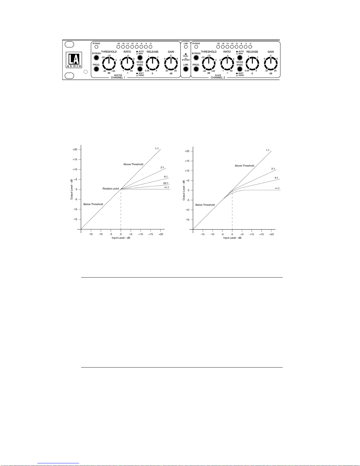
2.4 RATIO control
RATIO controls how much compression is applied to an input signal once it has
increased above threshold and refers to the final compression slope.
The RATIO markings around the control indicate how many dB the input signal
must increase to cause a 1dB rise in output level. A RATIO of 2:1 means the
input has to increase by 2dB for a 1dB change of output level. A 4:1 ratio requires
a 4dB increase of input level for a 1dB change of output, etc.
Page 6
A RATIO of ∞:1 effectively means that there is no increase in output level once
the input signal has reached THRESHOLD reference i.e. limiting. The following
diagrams shows the difference between HARD and SOFT knee compression at a
number of different RATIOs. THRESHOLD in the diagrams is set to 0dB.
Fig 2.1: HARD knee compression Fig 2.2: SOFT knee compression
2.5 AUTO-MAN switch
In the AUTO mode (switch out), Attack and Release times are automatically
adjusted and are dependant on the dynamic content of the input signal.
AUTO mode has been designed to work with a wide range of vocal, instrument
and program sources and can therefore be used in most applications without
need to adjust attack and release times.
In MAN (manual) mode (switch in) Attack becomes program dependant and the
Release time is manually adjusted using the RELEASE control.
2.6 KNEE switch
Selects between HARD and SOFT knee compression curves - see Fig 2.1 and
Fig 2.2.
SOFT knee gives a gradual onset of compression and can provide subtle and un-
obtrusive level control.
Page 7
HARD knee compression provides tight control over signal levels above threshold
and is useful for creative applications or where a large amount of gain reduction,
such as limiting, is required.
2.7 RELEASE control
RELEASE is only active in MAN (manual) mode (AUTO-MAN switch in) and
adjusts the release time between 40mS and 4S.
2.8 GAIN control
The GAIN control on the C400 allows the output level from the compressor to be
attenuated or amplified by up to 20dB. Generally used to compensate for level
changes caused by the action of compression.
Please note:
As +20dB of gain can be added to the signal path it is possible to cause clipping.
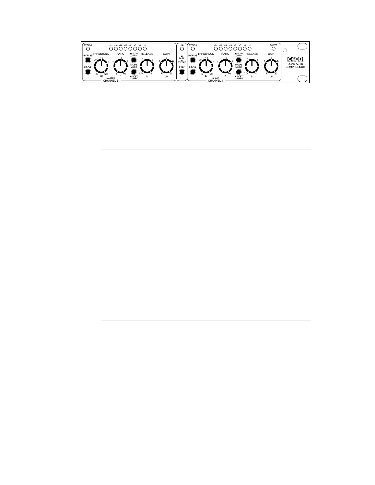
2.9 GAIN REDUCTION display
An 8 stage led bar graph meter that provides a visual indication of the amount of
gain reduction being applied to the input signal.
2.10 LINK switch
Pressing the LINK switch couples channels 1&2 and 3&4 for stereo operation.
Channels 1 and 3 become the masters, the controls on channels 2 and 4 are
disabled.
The side chain circuitry on the C400 uses true rms summing to ensure that the
signals in both the linked channels contribute equally to any gain reduction.
Page 8
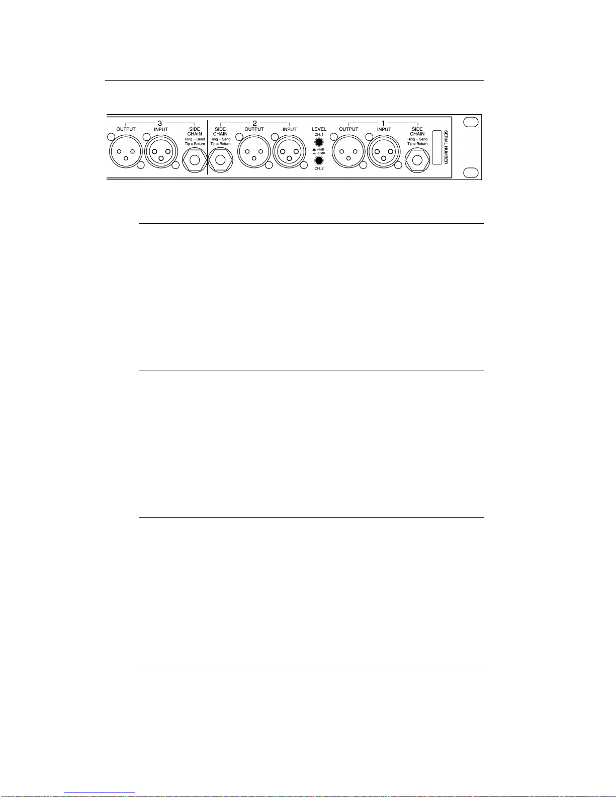
3.0 EXTERNAL CONNECTIONS
3.1 SIDECHAIN
The Side chain TRS jack allows connection of an external processor such as an
equaliser for frequency sensitive compression e.g. de-essing.
This is an unbalanced insert with Ring wired as Send and tip wired as return.
Please note:
Plugging a jack into the side chain connector breaks the control signal path which
must then be completed by the externally connected equipment.
3.2 INPUT
Electronically balanced Input with pin 2 wired hot (signal +).
Unbalanced operation is possible by joining pin 3 to pin 1 (signal ground) and
using pin 2 as signal hot (+).
Please note:
To maintain correct signal levels in un-balanced applications, pin 3 must be
joined to pin 1 and not left un-connected.
3.3 OUTPUT
Electronically balanced Output with pin 2 wired hot (signal +).
For un-balanced operation pin 3 can be joined to pin 1 i.e. pin 2 = signal hot and
pins 1&3 = ground (screen).
Please note:
To maintain correct signal levels in un-balanced applications, pin 3 must be
joined to pin 1 and not left un-connected.
3.4 LEVEL
These switches select the input and output operating level for each channel
between +4dBu (switch out) and -10dBV (switch in).
The Side Chain insert operates at -2dBu in both +4dBu and -10dBV modes.

Page 9
3.5 POWER
Mains power switch for C400
3.6 POWER INLET
Standard IEC mains inlet for use with a detachable mains cable.
See Section 3.4 for details of power requirements and fusing.
Please note:
The mains protection fuse is inside the unit, accessed by removing the top cover.
Ensure that the unit is disconnected from the mains supply before attempting to
replace the fuse.

Page 10
4.0 INSTALLATION
4.1 INSPECTION AND UNPACKING
The C400 has been carefully packed at our factory in a carton designed to
withstand handling in transit. Should the unit appear to have been damaged in
transit, notify your dealer immediately and do not discard any of the packing. The
carton should contain -
•The C400
•Power cord - country specific, please check
•Operator Manual (this book)
4.2 OPERATING ENVIRONMENT
The C400 is designed to operate between 0°C and 40°C (32-112°F) with relative
humidity no more than 80%. Should the units be installed in an equipment rack,
ensure that the ambient temperature conforms to these levels.
4.3 CE STANDARDS AND THE LOW VOLTAGE DIRECTIVE (LVD)
The C400 has been designed to comply with the latest Electromagnetic
Compatibility (EMC) regulations. However we recommend you do not operate the
unit close to strong emitters of electromagnetic radiation such as power
transformers, motors, mobile telephones or radio transmitters.
The unit should only be connected to a power supply of the type described in 4.4
POWER REQUIREMENTS or as marked on the unit. Disconnect the mains
supply before removing any cover.
4.4 POWER REQUIREMENTS
The C400 is factory configured for either 230V 50Hz ac or 115V 60Hz ac mains
operation. Please refer to the following diagram which shows the transformer
connections for 230V and 115V –
The rating of the rear panel fuse is shown on the cover -
230V 115V
T125mA T250mA All are slow blow type
Table of contents
Popular Compressor manuals by other brands


Emerson
Emerson Copeland Scroll Digital HLR Series Application guidelines

Drawmer
Drawmer 1968 MKII Operator's manual

Badger Air-Brush
Badger Air-Brush X-Air 80-8 User and maintenance instructions

Omnitronic
Omnitronic CL-166 user manual

Scheppach
Scheppach HC24V Translation from the original instruction manual

Ingersoll-Rand
Ingersoll-Rand centac C950 Planning and installation manual


