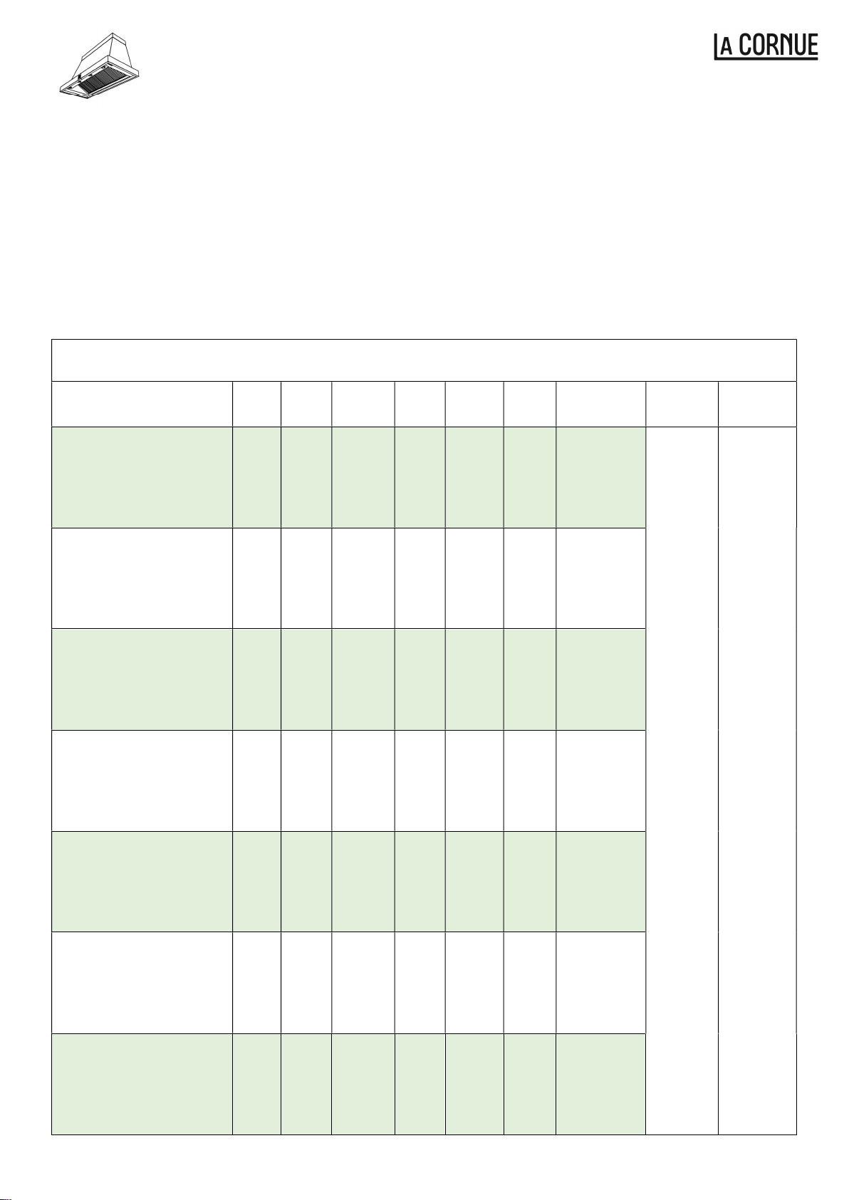
La Cornue Chateau 110 60Hz User manual

Chateau Range Hood
Hottes Chateau
(110-120V 60Hz Models)
Installation Instructions (EN) 1
Instructions d’Installation (F) 8
La Cornue
14, rue du Bois du Pont
Z.I les Béthunes
95310 Saint Ouen l’Aumône
FRANCE
Tel: +33 (0)1 34 48 36 36 Fax: +33 (0)1 34 64 32 65
Email: [email protected]om
www.lacornue.com

Chateau Hoods
2
INSTALLATION INSTRUCTIONS (EN)
INTRODUCTION 3
WARNINGS AND IMPORTANT INFORMATION 4
1 GENERAL INSTALLATION REQUIREMENTS 5
2 ELECTRICAL REQUIREMENTS 5
3 VENTILATION REQUIREMENTS 6
4 FIRE SAFETY 6
5 COOKER HOOD PERFORMANCE 6
6 DISTANCE FROM THE COOKTOP 7
7 SPECIFICATIONS 7
ILLUSTRATED INSTALLATION GUIDE 13
COOKER HOOD PARTS 14
COOKER HOOD LAYOUT AND FIXING POSITIONS 15
INSTALLATION SEQUENCE 16
RECIRCULATING HOODS 29
REPLACING THE CARBON FILTERS 30
OPERATING INSTRUCTIONS AND MAINTENANCE 31
WARRANTY AND SERVICE 35

Chateau Hoods
3
INTRODUCTION
This document is common to a range of standard width Chateau Hoods and provides you with the
dimensions, technical characteristics and installation instructions for these. Because we offer a bespoke
manufacturing service, it is possible that you may not find the description or technical characteristics of
your precise model in this guide, however, you may still refer to this guide for performing the installation
and using the appliance.
This guide is organised as follows:
WARNINGS AND IMPORTANT INFORMATION, containing important information regarding
safety, installation requirements and optimising hood performance (this section).
ILLUSTRATED INSTALLATION GUIDE for all standard models (Page 32)
USER OPERATING INSTRUCTIONS AND MAINTENANCE (Page 55).
WARNINGS AND IMPORTANT INFORMATION
Please read this guide before installing and using this appliance. We decline any responsibility
for any issues arising during installation or use of this cooker hood if the following warnings and
guidelines are not observed.
WARNING – TO REDUCE THE RISK OF A RANGE TOP GREASE FIRE:
a) Never leave surface units unattended at high settings. Boilovers cause smoking and greasy
spillovers that may ignite. Heat oils slowly on low or medium settings.
b) Always turn hood ON when cooking at high heat or when flambeing food (ie Crepes Suzette,
Cherries Jubilee, Pepercorn Beef Flambe.
c) Clean ventilation fans frequently. Grease should not be allowed to accumulate on fan or filter.
d) Use proper pan size. Always use cookware appropriate for the size of the surface element.
WARNING – TO REDUCE THE RISK OF INJURY TO PERSONS IN THE EVENT OF A RANGE TOP
GREASE FIRE, OBSERVE THE FOLLOWING:
a) SMOTHER FLAMES with a close-fitting lid, cookie sheet, or metal tray, then turn off the burner. BE
CAREFUL TO PREVENT BURNS. If the flames do not go out immediately, EVACUATE AND CALL
THE FIRE DEPARTMENT.
b) NEVER PICK UP A FLAMING PAN – You may be burned.
c) DO NOT USE WATER, including wet dishcloths or towels – a violent steam explosion will result.
d) Use an extinguisher ONLY if:
1) You know you have a Class ABC extinguisher, and you already know how to operate it.
2) The fire is small and contained in the area where it started.
3) The fire department is being called.
4) You can fight the fire with your back to an exit.

Chateau Hoods
4
1. GENERAL INSTALLATION REQUIREMENTS
This hood must be installed by competent technicians or qualified professionals in accordance with the
current regulations in the country where the appliance is installed.
This cooker hood is large and heavy so do not attempt to install it on your own. At least two people are
required to install this cooker hood.
To protect your hands, wear safety gloves during installation.
Fixings are only provided for fixing the hood to a flat and sturdy solid masonry wall. The fixings provided
may not be suitable for your wall, so installers are responsible for choosing suitable fixings that take
account of the hood’s weight and the support structure’s technical characteristics.
2. ELECTRICAL REQUIREMENTS
This appliance requires an ground connection.
A competent electrical technician must perform the electrical installation.
The extractor is a stationary appliance designed to be cord connected to the electrical supply.
The extractor must be isolated from the electrical supply before carrying out any cleaning or maintenance
operations.
GROUNDING INSTRUCTIONS
This appliance must be grounded. In the event of an electrical short circuit, grounding reduces the risk
of electric shock by providing an escape wire for the electrical current. This appliance is equipped with
a cord having a grounding wire with a grounding plug. The plug must be plugged into an outlet that is
properly installed and grounded.
WARNING – Improper grounding can result in a risk of electric shock.
Consult a qualified electrician if the grounding instructions are not properly understood, or if doubt
exists as to whether the appliance is properly grounded.
Do not use an extension cord. If the power supply cord is too short, having a qualified electrician
install an outlet near the appliance.

Chateau Hoods
5
3. VENTILATION REQUIREMENTS
Requirements of the relevant authorities concerning the discharge of exhaust air must be complied with.
Never use ducting that is smaller in diameter than the outlet spigot diameter of your cooker hood (see
Specifications). If you are connecting into a rectangular duct you must ensure that the cross-sectional
area of this duct is the same or larger than that of the outlet spigot.
Install ducting before fitting the hood to the wall to prevent debris entering the appliance. We recommend
the final connection at the cooker hood exhaust spigot is done using semi-rigid ducting for easier fitting
and removal and to provide tolerance for any misalignment between the extractor spigot and fixed
ductwork.
Note: We recommend duct holes are 25mm larger than the ducting to enable cables to run alongside
(such as remote motor or power cables) and to make installing ducting easier.
4. FIRE SAFETY
To reduce fire hazards, use metal ducting components.
Pay particular attention to fire risk when frying.
Do not flambé under the extractor.
To minimise the risk of fire, all instructions relating to cleaning the grease filters and removing grease
deposits must be adhered to.
5. COOKER HOOD PERFORMANCE
The most important influence on the performance of the extractor is the design of the ducting which takes
the exhaust air from the extractor to the outside.
Never use ducting that is smaller in diameter than the outlet spigot diameter of your cooker hood (see
Specifications). If you are connecting into a rectangular duct you must ensure that the cross-sectional
area of this duct is the same or larger than that of the outlet spigot.
The duct route length should be kept as short as possible with as few bends as possible.
A route with more than two 90-degree bends can significantly degrade the performance of the extraction
system.
WARNING
Proper care must be taken to ensure that the negative pressures caused by high performance
extraction systems do not adversely affect the safe operation of certain types of fuel-burning appliances
(gas, oil or solid fuel), including those installed in the kitchen and possibly also those installed in other
parts of the house.
Where such fuel-burning appliances are installed, adequate ventilation MUST be provided in the room
of installation, located and sized such that the negative pressure in the room created by the extractor
does not exceed 4Pa.
In case of doubt, do not operate the extractor and fuel-burning appliance(s) simultaneously and consult
an appropriate (for the fuel type) expert for advice.
WARNING
The exhaust air must not be discharged into a flue which is used for exhausting fumes from
appliances supplied with energy other than electricity, e.g. oil or gas-fired central heating boilers,
gas-fired water heaters, etc.

Chateau Hoods
6
6. DISTANCE FROM THE COOKTOP
The minimum distance between the range hob burners and the bottom of the extractor is essential to
prevent overheating of the extractor and its components.
To optimise the performance of your cooker hood we recommend installing it at a distance of 850 –
900mm from the cooktop.
For electric cooktops the minimum distance between the cooktop and the cooker hood is 750mm.
For gas cooktops the minimum distance between the cooktop and the cooker hood is 850mm.
7. SPECIFICATIONS
Chateau Cooker Hood Specifications - Internal Motor
Model
Hood
Width
(mm)
Weight
(Kg)
Duct
Diameter
LED
Lights
Grease
Filter
Quantity
Total
Power
(Watts)
Internal Motor
Type
Electrical
Supply
Control
System
LCH – 2000 – 120V 60Hz
(Grand Palais 180
Range Hood)
2000 134 200mm
6 6 720 W
2 x GX1000
600 CFM
Blowers
120 V ac
60 Hz
Single
Phase +
Earth
Electronic
Push
Buttons &
Remote
Control
LCH – 1850 – 120V 60Hz
(Chateau165
Range Hood)
1850 124 200mm
5 5 716 W
2 x GX1000
600 CFM
Blowers
LCH – 1700 – 120V 60Hz
(Chateau 150
Range Hood)
1700 115 200mm
5 5 716 W
2 x GX1000
600 CFM
Blowers
LCH – 1550 – 120V 60Hz
(Grand Chatalet 135
Range Hood)
1550 105 200mm
4 4 713 W
2 x GX1000
600 CFM
Blowers
LCH – 1400 – 120V 60Hz
(Chateau 120
Range Hood)
1400 96 200mm
4 4 713 W
2 x GX1000
600 CFM
Blowers
LCH – 1100 – 120V 60Hz
(Grand Castel 90
Range Hood)
1100 75 150mm
3 2 360 W
1 x GX1000
600 CFM
Blower
LCH – 950 – 120V 60Hz
(Castel 75
Range Hood)
950 69 150mm
3 2 360 W
1 x GX1000
600 CFM
Blower

Chateau Hoods
7
This “crossed-out bin" logo found on all products means that the equipment cannot be
disposed of with other waste, that it is the object of a selective collection with a view to
recovery, reuse or recycling.
NOW REFER TO THE ILLUSTRATED INSTALLATION GUIDE ON
PAGE 13 FOR DETAILED COOKER HOOD FITTING INSTRUCTIONS

Hottes Chateau
INSTRUCTIONS D’INSTALLATION (F)
INTRODUCTION 9
AVERTISSEMENTS ET INFORMATIONS IMPORTANTS 9
1 EXIGENCES GÉNÉRALES D'INSTALLATION 9
2 EXIGENCES ÉLECTRIQUES 9
3 EXIGENCES DE VENTILATION 10
4 SÉCURITÉ INCENDIE 10
5 PERFORMANCE DE LA HOTTE 10
6 DISTANCE DE LA TABLE DE CUISSON 11
7 SPECIFICATIONS 11
GUIDE D'INSTALLATION ILLUSTRÉE 13
PIÈCES DE HOTTE 14
DISPOSITION DE LA HOTTE ET POSITIONS DE FIXATION 15
SÉQUENCE D'INSTALLATION 16
HOTTES À RECYCLAGE 29
REMPLACEMENT DES FILTRES AU CARBONE 30
INSTRUCTIONS D'UTILISATION ET D’ENTRETIEN 33
GARANTIE et SERVICE 36

Hottes Chateau
9
INTRODUCTION
Ce document est commun à une gamme de hottes de Chateau de largeur standard et vous fournit les
dimensions, les caractéristiques techniques et les instructions d'installation pour celles-ci. Parce que
nous offrons un service de fabrication sur mesure, il est possible que vous ne trouviez pas la description
ou les caractéristiques techniques de votre modèle précis dans ce guide, cependant, vous pouvez
toujours consulter ce guide pour effectuer l'installation et l'utilisation de l'appareil.
Ce guide est organisé comme suit:
AVERTISSEMENTS ET INFORMATIONS IMPORTANTS, contenant des informations
importantes concernant la sécurité, les exigences d'installation et l'optimisation des performances
de la hotte (cette section).
GUIDE D'INSTALLATION ILLUSTRÉE pour tous les modèles standard (Page 32).
INSTRUCTIONS D'UTILISATION ET D’ENTRETIEN (Page 53).
AVERTISSEMENTS ET INFORMATIONS IMPORTANTS
Veuillez lire ce guide avant d'installer et d'utiliser cet appareil. Nous déclinons toute
responsabilité pour tout problème survenant lors de l'installation ou de l'utilisation de cette hotte
si les avertissements et directives suivants ne sont pas respectés.
1. EXIGENCES GÉNÉRALES D'INSTALLATION
Cette hotte doit être installée par des techniciens compétents ou des professionnels qualifiés
conformément aux réglementations en vigueur dans le pays où l'appareil est installé.
Cette hotte étant grande et lourde, n'essayez pas de l'installer vous-même. Au moins deux personnes
sont nécessaires pour installer cette hotte
Pour vous protéger les mains, portez des gants de sécurité lors de l'installation.
Les fixations ne sont fournies que pour fixer la hotte à un mur de maçonnerie plat et solide. Les fixations
fournies peuvent ne pas convenir à votre mur, les installateurs sont donc responsables du choix des
fixations appropriées qui tiennent compte du poids de la hotte et des caractéristiques techniques de la
structure de support.
2. EXIGENCES ÉLECTRIQUES
Cet appareil doit être mis à la terre.
Un technicien électricien compétent doit realises l’installation électrique.
L'extracteur est un appareil fixe conçu pour être connecté par un câblage fixe à l'alimentation électrique.
L'extracteur doit être alimenté à partir d'une alimentation électrique monophasée de 120Vac à l'aide d'un
embranchement commuté équipé d'un fusible de 3A. Les moyens de déconnexion de l'alimentation
doivent avoir une séparation de contact minimale de 3mm dans tous les pôles. Alternativement, un
moyen de déconnexion dans le câblage fixe selon les règles de câblage pertinentes doit être installé.
L'alimentation électrique est connectée au câble d'alimentation de la hotte comme suit:
CONNEXIONS DE CÂBLE D'ALIMENTATION
Phase Noir
Neutre Blanc
Terre
Vert
/J
aune
L'extracteur doit être isolé de l'alimentation électrique avant toute opération de nettoyage ou d'entretien.

Hottes Chateau
10
3. EXIGENCES DE VENTILATION
Il faut respecter les normes en vigueur concernant le rejet de l’air.
N'utilisez jamais de conduits d'un diamètre inférieur au diamètre de sortie de votre hotte (voir les
spécifications). Si vous vous connectez à un conduit rectangulaire, vous devez vous assurer que la
section de ce conduit est égale ou supérieure à celle du sortie d'évacuation.
Installez les conduits avant d'installer la hotte sur le mur pour éviter que des débris ne pénètrent dans
l'appareil. Nous recommandons que la connexion finale à la sortie d'évacuation de la hotte de cuisinière
se fasse en utilisant des conduits semi-rigides pour faciliter le montage et le démontage et pour fournir
une tolérance pour tout désalignement entre l'extracteur et les conduits fixes.
Remarque: Nous recommandons que les trous de conduit soient plus grands de 25mm que les conduits
pour permettre le passage des câbles (comme les câbles de moteur externe ou d'alimentation) et pour
faciliter l'installation des conduits.
4. SÉCURITÉ INCENDIE
Pour réduire les risques d'incendie, utilisez des composants de conduits métalliques.
Portez une attention particulière aux risques d'incendie lors de la friture.
Ne flambez pas sous l'extracteur.
Pour minimiser les risques d'incendie, toutes les instructions relatives au nettoyage des filtres à graisse
et à l'élimination des dépôts de graisse doivent être respectées.
5. PERFORMANCE DE LA HOTTE
L'influence la plus importante sur la performance de l'extracteur est la conception de la conduite qui
prend l'air d'échappement de l'extracteur à l'extérieur.
N'utilisez jamais de conduits d'un diamètre inférieur au diamètre de sortie de votre hotte (voir les
spécifications). Si vous vous connectez à un conduit rectangulaire, vous devez vous assurer que la
section de ce conduit est égale ou supérieure à celle du sortie d'évacuation.
La longueur de la route du conduit doit être aussi courte que possible avec le moins de coudes possible.
Une route comportant plus de deux virages à 90 degrés peut dégrader considérablement les
performances du système d'extraction.
ATTENTION
Il convient de veiller à ce que les pressions négatives provoquées par les systèmes d'extraction haute
performance ne nuisent pas à la sécurité de fonctionnement de certains types d'appareils à
combustion (gaz, pétrole ou combustibles solides), y compris ceux installés dans la cuisine et
éventuellement ceux installés dans d'autres parties de la maison.
Lorsque de tels appareils sont installés, une ventilation adéquate DOIT être prévue dans la pièce
d'installation, située et dimensionnée de telle sorte que la pression négative dans la pièce créée par
l'extracteur n'excède pas 4Pa.
En cas de doute, n'utilisez pas simultanément l'extracteur et le (s) appareil (s) combustible (s) et
consultez un expert compétent (pour le type de carburant).
ATTENTION
L'air évacué ne doit pas être évacué dans une cheminée qui est utilisée pour évacuer les fumées
des appareils alimentés en énergie autre que l'électricité, par ex. les chaudières de chauffage central
au mazout ou au gaz, les chauffe-eau au gaz, etc.

Hottes Chateau
11
6. DISTANCE DE LA TABLE DE CUISSON
La distance minimale entre les brûleurs de cuisinière de gamme et le fond de l'extracteur est essentielle
pour empêcher la surchauffe de l'extracteur et de ses composants.
Pour optimiser les performances de votre hotte, nous vous recommandons de l'installer à une distance
de 850 à 900 mm de la table de cuisson.
Pour les tables de cuisson électriques, la distance minimale entre la table de cuisson et la hotte
est de 750 mm.
Pour les tables de cuisson au gaz, la distance minimale entre la table de cuisson et la hotte est
de 850 mm.
7. SPECIFICATIONS
Spécifications - Moteur Interne
Model
Largeur
(mm)
Poids
(Kg)
Sortie
Diameter
Lumières
LED
Quantité
de filtre
Puissance
Electrique)
Moteur Tension Contrôle
LCH – 2000 – 120V 60Hz
(Hotte Grand Palais 180) 2000 134 200mm
6 6 720 W
2 x GX1000
600 CFM
Blowers
120 V ac
60 Hz
Single
Phase +
Earth
Electronic
Push
Buttons &
Remote
Control
LCH – 1850 – 120V 60Hz
(Hotte Chateau165) 1850 124 200mm
5 5 716 W
2 x GX1000
600 CFM
Blowers
LCH – 1700 – 120V 60Hz
(Hotte Chateau 150) 1700 115 200mm
5 5 716 W
2 x GX1000
600 CFM
Blowers
LCH – 1550 – 120V 60Hz
(Hotte Grand Chatalet 135)
1550 105 200mm
4 4 713 W
2 x GX1000
600 CFM
Blowers
LCH – 1400 – 120V 60Hz
(Hotte Chateau 120) 1400 96 200mm
4 4 713 W
2 x GX1000
600 CFM
Blowers
LCH – 1100 – 120V 60Hz
(Hotte Grand Castel 90) 1100 75 150mm
3 2 360 W
1 x GX1000
600 CFM
Blower
LCH – 950 – 120V 60Hz
(Hotte Castel 75) 950 69 150mm
3 2 360 W
1 x GX1000
600 CFM
Blower

Hottes Chateau
12
Ce pictogramme de la "poubelle barrée" apposé sur tous les produits signifieque
l'équipement ne peut être jeté avec les autres déchets, qu’il fait I’objet d'une collecte
sélective en vue de sa valorisation, réutilisation ou recyclage.
REPORTEZ-VOUS MAINTENANT AU GUIDE D'INSTALLATION
ILLUSTRÉ À LA PAGE 13 POUR OBTENIR DES INSTRUCTIONS
DÉTAILLÉES SUR LE MONTAGE DE LA HOTTE.

Installation
13
ILLUSTRATED INSTALLATION GUIDE
GUIDE D'INSTALLATION ILLUSTRÉE

Installation
14
LISTE DES PIECES
1 Frette
2 Manteau de la Hotte
3 Couvre-joint
4 LED Lumière
5 Filtre
6 Bandeau
7 Boutons Electroniques
8 Support Mural
PARTS LIST
1 Upper Band
2 Hood Cover
3 Decorative Trim Connector
4 LED Lights
5 Filter
6 Decorative Trim
7 Control Buttons
8 Wall Bracket

Installation
15
COOKER HOOD LAYOUT & FIXING POSITIONS
SCHÉMA DE LA HOTTE DE CUISINIERE ET POSITIONS DE FIXATION
Model Dimension (mm)
A B C D E F G
Grand Palais 180 2000 1600 748 456 760 675 200
Chateau 165 1850 1450 673 418 685 600 200
Chateau 150 1700 1300 598 381 610 525 200
Chatalet 135 1550 1150 523 344 535 450 200
Chateau 120 1400 1000 448 306 460 375 200
Grand Castel 90 1100 700 298 310 310 225 150
Castel 75 950 550 223 235 235 225 150

Installation
16
STEP / ÉTAPE 1
(EN) Fix the bracket to the wall as shown in the diagram using fixings suitable for your wall.
(F) Fixez le support mural au mur comme indiqué sur le schéma en utilisant des fixations adaptées à votre
mur.

Installation
17
STEP / ÉTAPE 2
(EN) Secure the appliance to the wall bracket as shown.
(F) Fixez l'appareil au support mural comme indiqué.

Installation
18
STEP / ÉTAPE 3
(EN) Secure the appliance to the wall through the lower fixing holes as shown.
(F ) Fixez l'appareil au mur à travers les trous de fixation inférieurs comme indiqué.

Installation
19
STEP / ÉTAPE 4
(GB) DISCONNECT ELECTRICAL SUPPLY BEFORE PROCEEDING FURTHER!!
(F) DÉBRANCHER L'ALIMENTATION ÉLECTRIQUE AVANT DE PROCÉDER AUTREMENT!!
(EN) Wire the appliance to the electrical supply via an isolator and in accordance with local regulations.
(F) Brancher l'appareil à l'alimentation électrique via un isolateur et conformément à la réglementation locale

Installation
20
STEP / ÉTAPE 5
(EN) Connect ducts according to your preferred exhaust method. See below options.
WARNING – TO REDUCE THE RISK OF FIRE, USE ONLY METAL DUCTWORK
(F) Connectez les conduits selon votre méthode d'échappement préférée. Voir les options ci-dessous.
AVERTISSEMENT - POUR RÉDUIRE LES RISQUES D'INCENDIE, UTILISEZ UNIQUEMENT DES
CONDUITS EN MÉTAL
(EN) Rear outlet exhaust Top outlet exhaust
(F) Sortie d'échappement arrière Sortie d'échappement supérieure
Ø = P
34
This manual suits for next models
1
Table of contents
Other La Cornue Ventilation Hood manuals