manuals.online logo
Brands
  1. Home
  2. •
  3. Brands
  4. •
  5. La Crosse
  6. •
  7. Weather Station
  8. •
  9. La Crosse WS-9049U-IT User manual

La Crosse WS-9049U-IT User manual

INSTANT TRANSMISSION is the state-of-the-art new
wireless transmission technology, exclusively
designed and developed by LACROSSE
TECHNOLOGY. INSTANT TRANSMISSION offers you
an immediate update (every 4 seconds!) of all your
outdoor data measured from the transmitters: follow
your climatic variations in real-time!
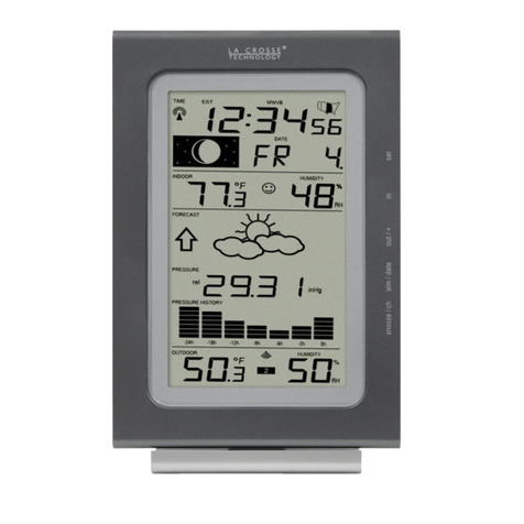
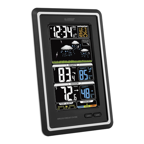
Wireless Forecast Station
Model WS-9049U-IT | Quick Setup Guide
Be prepared for any weather and keep cozy with this wireless forecast
station. The WS-9049U-IT forecast station anticipates weather
conditions with outdoor temperature and barometric pressure data. The
forecast is depicted with three different weather icons and tendency
arrows. For exact time, the forecast station’s time and date reset daily
via WWVB radio transmissions from the US Atomic Clock. The forecast
station illustrates the moon’s phase and presents barometric pressure
history for the past 24 hours in a bar graph.
SETUP INSTRUCTIONS STEP BY STEP
STEP 1:
•Ensure that the transmitter is within 10 feet of the
forecast station.
•Remove battery cover from TX29UDTH-IT transmitter.
•Insert 2 new AAA batteries (not included) into the
transmitter. Observe the correct polarity.
•The temperature and humidity should appear in the
LCD of the transmitter.
STEP 2:
•Remove battery cover from the forecast station
•Insert 2 new C batteries (not included) into the
back of the forecast station. Observe the correct
polarity (see marking inside the battery
compartment).
•Within 3 minutes the forecast station will show
readings in the outdoor temperature area.
Note:Allow the forecast station and the
transmitter to stay within 10 feet of each other
for the first 15 minutes of set up.
•Do Not Mix Old and New Batteries
•Do Not Mix Alkaline, Standard, Lithium or Rechargeable
Batteries
TROUBLESHOOTING
•If the forecast station does not display the outdoor temperature after
3 minutes, remove the batteries from both units and start the setup
process again.
•For optimal 915MHz signal reception, the outdoor transmitter should
be placed within 330 feet (100 meters) from the indoor Forecast
Station.
•The outdoor temperature reception icon will flash during
initial setup, for up to three minutes, until it connects with
the transmitter.
•It will also flash about every 4 seconds afterwards, as the forecast
station receives an update.
SET TIME
Use the SET button to move through the program menu. Use the
OUT/+ button to change a value.
•CONTRAST: Hold the SET button for five seconds. The letters lcd
4will flash. Use the OUT/+ button to adjust the contrast. Press and
release the SET button once to confirm and move to time zone.
•TIME ZONE: The -5h will flash. Use the OUT/+ buttons to change
the Time Zone. North American Time Zones are negative numbers:
-4h Atlantic, -5h Eastern, -6h Central, -7h Mountain, -8h Pacific,
-9h Alaskan and -10h Hawaiian time zone. Press the SET button
once to confirm and move to daylight saving time indicator.
•DAYLIGHT SAVING TIME: DSt will show and either ON or OFF will
flash.Most states use DST, so this should be ON. However, if your
location does not use DST, use the OUT/+ button to turn it
OFF. Press the SET button once to confirm and move to radio-
controlled time ON/OFF.
•RADIO-CONTROLLED TIME: RCC will show and either ON or OFF
will flash. Use the OUT/+ button to select the RCC reception. Press
and release the SET button once to confirm and move to 12/24 hour
time.
•12/24-HOUR TIME: 12h will flash on the display. Use OUT/+ button
to change from 12 to 24 hour format time. Press and release the
SET button once and move to the hour.
Note:When in 24-hour time, the date will read first then the month.
•HOUR: The Hour will flash. Use the OUT/+ button to set the
Hour. If using 12-hour Time Mode, be sure to set the hour for am or
pm. Press and release the SET button once to confirm and move to
the minutes.
•MINUTES: The Minutes will flash. Use the OUT/+ button to set the
minutes. Press and release the SET Button once to confirm and
move to the year.
•YEAR: The Year will flash. Use the OUT/+ button to set the
Year. Press and release the SET button once to confirm and move
to the month.
•MONTH: The Month will flash. Use the OUT/+ button to set the
Month. Press and release the SET button once to confirm and
move to the date.
•DATE: The numeric day will flash. Use the OUT/+ button to set the
date correctly. Press and release the SET Button once to confirm
and move to the Fahrenheit or Celsius selection.
•FAHRENHEIT OR CELSIUS: ºF will flash. Use the OUT/+ button to
select your preference. Press and release the SET button once to
confirm and move to the air pressure unit of measure.
•AIR PRESSURE UNITS: The barometric air pressure unit of
measurement (inHg) will flash. Press and release the OUT/+ button
to select inHg (inches of Mercury) or hPa (hectopascal or milibars).
Press and release the SET button once to confirm and move to set
relative air pressure.
•RELATIVE AIR PRESSURE: The Relative Barometric Air Pressure
number setting will flash 29.92 inHg or 1012.8 hPA (defaults).Press
and release the OUT/+ button to increase the setting or the IN
button to decrease the setting. Press and release the SET button
once to confirm and move to the forecast sensitivity.
•FORECAST SENSITIVITY: Two air pressure tendency arrows will
appear and the number 3will flash in the pressure area. Press and
release the ALM/+ button to select the desired Forecast Sensitivity
setting.
Note: The lowest number is used near the coastline, the highest
number is for the desert, and middle number is for everywhere else.
This product offers:
Press and release the SET or SNOOZE/CH button once to return to
normal display.
WWVB RADIO-CONTROLLED TIME SIGNAL
The NIST radio station, WWVB, is located in Ft. Collins, Colorado and
transmits the exact time signal continuously throughout the United
States at 60 kHz. The signal can be received up to 2,000 miles away
through the internal antenna in the forecast station. However, due to
the nature of the Earth’s Ionosphere, reception is very limited during
daylight hours. The forecast station will search for a signal every night
when reception is best.
Once the outdoor temperature is displayed on the forecast station, the
WWVB tower icon in the station will start flashing in the top center of
the LCD. This indicates that the forecast station has detected a radio
signal and is trying to receive it. When the time code is received, the
WWVB tower becomes permanently lit and the time will be displayed.
If the tower icon flashes, but does not set the time or the
WWVB tower does not appear at all, then please take note of
the following:
•Recommended distance to any interfering sources like computer
monitors or TV sets is a minimum of 6 feet (2 meters).
•Within ferro-concrete rooms (basements, superstructures), the
received signal is naturally weakened. In extreme cases, please
place the unit close to a window and/ or point its front or back
towards the Fort Collins, Colorado.
•During nighttime, the atmospheric disturbances are usually less
severe and reception is possible in most cases. A single daily
reception is adequate to keep the accuracy deviation below 1
second.
Note:In case the forecast station is not able to detect the WWVB-
signal (disturbances, transmitting distance, etc.), the time can be
manually set (please refer to notes SET TIME).
SET TIME ALARM
Press and hold the ALM/DATE button for five
seconds. The alarm hour will flash to the
right of the moon phase.
•HOUR: Press and release the IN button to adjust the hour (am or
pm).
•MINUTE: Press and release the OUT/+ button to adjust the
minute. Press SNOOZE/CH to return to normal display.
Note: This is a crescendo alarm that increases in volume over the two
minutes the alarm will sound. After the two minutes the alarm will shut
off and sound again in 24 hours.
ACTIVATE/DEACTIVATE ALARM
•ACTIVATE: Press and release the ALM/DATE button to toggle
between the alarm and day/date. When the alarm time and alarm
icon are showing to the right of the moon phase, the alarm is
activated.
•DEACTIVATE ALARM: Press and release theALM/DATE button and
alarm icon will disappear. When the day and date are showing, the
alarm is deactivated.
SNOOZE
•When the time alarm sounds, press and release the SNOOZE/CH
button. The snooze will be activated for 10 minutes.
•Press and release any button, other than the SNOOZE/CH button to
silence the alarm.
LOW BATTERY ICON
•The low battery icon will show when the forecast
station needs fresh batteries.
MIN/MAX TEMPERATURE READINGS
This forecast station will show the min/max temperatures from setup,
until you reset the min/max temperatures or remove the batteries from
the forecast station.
Note: To view a 24-hour min/max reading, reset the min/max
temperatures at the same time each day.
VIEW INDOOR MIN/MAX RECORDS: Press and release the IN
button to display Indoor Max, Min and Current records.
RESET INDOOR MIN/MAX RECORDS: Press and release the IN
button to select the record you wish to reset, either MAX or
MIN. Press and hold the SET button for five seconds. The record is
now reset to the Current Date, Temperature and Humidity.
Note: Each Min or Max value will need to be reset separately.
VIEW OUTDOOR MIN/MAX RECORDS: Press and release the
OUT/+ button to display the Outdoor Max, Min and Current records.
RESET OUTDOOR MIN/MAX RECORDS: Press and release the
OUT/+ button to select the record you wish to reset. Press and hold
the SET button for five seconds. The record is now reset to the Current
Date, Temperature and Humidity.
Note: Each Min or Max value will need to be reset separately.
Note: Press the SNOOZE/CH to view outdoor minimum/maximum
reading when using multiple transmitters.
OUTDOOR TEMPERATURE CHANNEL INDICATOR
When using multiple transmitters, the
channel indicator will show between the
outdoor temperature and humidity reading.
Press and release the SNOOZE/CH button to view channel 1, 2 or 3
on the forecast station when multiple transmitters are used.
Note:You cannot change channels if only one transmitter is
connected.
Note: The channel indicator only shows when more than one
transmitter is received.
MOON PHASE
The moon phase is based on the year, month and date, set manually
or set by the WWVB signal.
COMFORT LEVEL ICON FOR INDOOR TEMPERATURE AND HUMIDITY
The comfort level indicator appears in between the indoor temperature
and humidity.
Happy Face will display when the temperature is between 68 and 79
degrees Fahrenheit (20 and 25.9 degrees Celsius) and the humidity is
between 45% and 64% Rh.
Sad Face will be displayed when the temperature and humidity are
outside the above mentioned ranges.
BAROMETRIC PRESSURE READINGS
NUMERIC AIR PRESSURE READING: The actual barometric air
pressure is displayed directly under the weather forecast icon. You
can set this to your local reporting station through the program menu.
AIR PRESSURE HISTORY BAR CHART:
The bar graph shows the recorded air
pressure over the past 24-hours in hPa.
The horizontal axis shows the hours at
increments of -24 hours, -18 hours, -12
hours, -9 hours, -6 hours, -3 hours and 0 hours.
The 0h on the horizontal axis indicates the current hour, thus the
current air pressure. Each bar on the bar graph represents a value of
0.03 hPa, and each bar also has a corresponding value on the vertical
axis. The vertical axis is set in hPa; the '0' on the axis represents the
current hPa and how high or low the past air pressure was as
compared to the current pressure.
DETERMINE AIR PRESSURE TRENDS: If the bars are rising (higher
on the right than the left), then the air pressure has a rising trend, and
the weather should improve. If the bars are dropping (lower on the
right side that the left), then the air pressure has a falling trend and the
weather should worsen.
Note: The bar chart will constantly scroll to avoid burnout of the LCD.
This feature cannot be turned off.
WEATHER FORECAST ICONS
The weather forecasting feature is estimated to be 75% accurate. The
weather forecast is based solely upon the change of air pressure over
time. The icons are predicting 6-12 hours in the future. It may be sunny
out your window, but the pressure is falling so the forecast station will
show clouds with rain icon.
WEATHER ICONS
There are 3 possible weather icons that will be displayed in the LCD :
Sunny:Indicates that the weather is expected to improve (not that the
weather will be sunny).
Sun with Clouds:Indicates that the weather is expected to be fair (not
that the weather will be sunny with clouds).
Clouds with Rain:Indicates that the weather is expected to get worse
(not that the weather will be rainy).
The weather icons change when the unit detects a change in air
pressure. If the symbols do not change then the weather has not
changed, or the change has been slow and gradual.
FORECAST TENDENCY INDICATOR
There are 2 weather tendency arrows, one that points up and one that
points down. These arrows reflect current changes in the air pressure.
Up Arrow:Indicates that the air pressure is increasing and the
weather is expected to improve or remain good
Down Arrow:Indicates that the air pressure is decreasing and the
weather is expected to become worse or remain poor
No Arrow:Indicates the pressure is stable
SETUP WITH MULTIPLE TRANSMITTERS
The wireless forecast station will accommodate up to three remote
outdoor transmitters (TX29UDTH-IT). The SNOOZE/CH button allows
you to easily see the temperature in various locations: outdoors, baby’s
room, greenhouse, basement, etc.
1. Insert 2 new AA batteries (not included) in the first outdoor
transmitter.
2. Insert 2 new C batteries (not included) into the back of the forecast
station. The forecast station will light up and show, indoor
temperature, humidity and pressure.
3. When the reading appears in the outdoor temperature area, move to
the second transmitter.
4. Insert 2 new AA batteries in the second outdoor transmitter. In a
short time, the outdoor temperature area should show a temperature
reading on channel 1 and on channel 2.
5. When the readings appear in the outdoor temperature area (channel
2), move to the third transmitter.
6. Insert 2 new AA batteries in the third outdoor transmitter.
7. When the respective temperature & humidity for each of the
selected channels (1, 2, or 3) will appear on the main unit. Allow the
transmitters and wireless forecast station to sit near each other for
15 minutes to lock in the signals.
Press and release the SNOOZE/CH button to view channel 1, 2 or 3
on the forecast station when multiple transmitters are used.
Note:You cannot change channels if only one transmitter is
connected.
CARE AND MAINTENANCE
•Do Not Mix Old and New Batteries
•Do Not Mix Alkaline, Standard, Lithium or Rechargeable Batteries
•Do not expose the forecast station to extreme temperatures, vibration or
shock. Keep forecast station dry.
•Clean forecast station with a soft damp cloth. Do not use solvents or
scouring agents.
•The forecast station is not a toy. Keep it out of reach of children.
•The forecast station is not to be used for medical purpose or for public
information, but is determined for home use only.
•The specifications of this forecast station may change without prior notice.
•Improper use or unauthorized opening of housing will void the warranty.
SPECIFICATIONS
Temperature measuring range:
Indoor: 14.2ºF to 139.8ºF with 0.2ºF resolution
-9.9ºC to +59.9ºC with 0.1°C resolution
(“OF.L” displayed if outside this range)
Outdoor: -39.8ºF to +139.8ºF with 0.2ºF
resolution
-39.9ºC to +59.9ºC with 0.1°C resolution
(“OF.L” displayed if outside this range)
Humidity range:
Indoor humidity range: 20% to 95% with 1% resolution
(Display “- -“if temperature is OF.L;
display “- -“if < 20% and “95%” if > 95%)
Outdoor humidity range: 1% to 99% with 1% resolution
(Display “- -“if outside temperature is
OF.L)
Data checking intervals
Indoor Temperature: Every 15 seconds
Humidity: Every 20 seconds
Air pressure checking interval: Every 15 seconds (or every 15 minutes
if data is lost and displays “--.-“)
Outdoor temperature/humidity: Every 4 seconds
Transmission range: Up to 330 feet (open space)
Power consumption: (alkaline batteries recommended)
Wireless forecast station: 2 x C, IEC LR14, 1.5V (not included)
TX29UDTH-IT transmitter: 2 xAA, IEC LR6, 1.5V (not included)
Battery life: Up to 24 months with reputable battery
brands
Dimensions (L x W x H):
Forecast Station: 7.20“ x 1.49“ x 7.36“ / 183 x 38 x 187
mm
TX29UDTH-IT transmitter: 1.50” x 0.83” x 5.05” /
38.2mm x 21.2mm x 128.3mm
POSITIONING THE WIRELESS FORECAST STATION
Before wall mounting, please check that the outdoor data can be
received from the desired locations. The Forecast Station should
be mounted near an exterior wall with the front or back facing
toward Ft. Collins, Colorado for best WWVB reception.
FOLDOUT TABLE STANDS: Simply unfold the stands on the
back, and place the forecast station in an appropriate location.
TO WALL MOUNT: Fix a screw (not supplied) into the desired
wall, leaving the head extended out by about 0.2” (5mm).
Place the wireless forecast station onto the screw, using the
hanging hole on the backside. Gently pull the wireless forecast
station down to lock the screw.
POSITIONING THE OUTDOOR TRANSMITTER
To achieve a true temperature reading, mount in a shaded location.
While the outdoor temperature sensor is weather resistant, avoid
submersion in water or snow. We recommend that you mount the
outdoor temperature sensor on an outside North-facing wall. The
transmission range is 330ft(open air). Obstacles such as walls,
concrete and large metal objects can reduce the range. Place both
units in desired location, and wait approximately 15 minutes before
permanently mounting to ensure that there is proper reception.
Wall Mount:
1. Remove the mounting bracket from the outdoor
temperature sensor .
2. Place the mounting bracket in the desired shaded location
(wall or table).
3. Through the screw holes of the bracket, mark the
mounting surface with a pencil.
4. Screw mounting bracket onto the mounting surface.
Ensure that the screws are flush with the bracket.
5. Insert the outdoor temperature sensor into the bracket.
Note:Mounting with adhesive tape is not recommended as
a permanent mounting solution. Only use the adhesive tape
during set-up process.
WARRANTY INFORMATION
La Crosse Technology, Ltd provides a 1-year limited warranty on this product
against manufacturing defects in materials and workmanship.
This limited warranty begins on the original date of purchase, is valid only on
products purchased and used in North America and only to the original purchaser
of this product. To receive warranty service, the purchaser must contact La
Crosse Technology, Ltd for problem determination and service procedures.
Warranty service can only be performed by a La Crosse Technology, Ltd
authorized service center. The original dated bill of sale must be presented upon
request as proof of purchase to La Crosse Technology, Ltd or La Crosse
Technology, Ltd’s authorized service center.
La Crosse Technology, Ltd will repair or replace this product, at our option and at
no charge as stipulated herein, with new or reconditioned parts or products if
found to be defective during the limited warranty period specified above. All
replaced parts and products become the property of La Crosse Technology, Ltd
and must be returned to La Crosse Technology, Ltd. Replacement parts and
products assume the remaining original warranty, or ninety (90) days, whichever
is longer. La Crosse Technology, Ltd will pay all expenses for labor and materials
for all repairs covered by this warranty. If necessary repairs are not covered by
this warranty, or if a product is examined which is not in need or repair, you will
be charged for the repairs or examination. The owner must pay any shipping
charges incurred in getting the La Crosse Technology, Ltd product to a La Crosse
Technology, Ltd authorized service center. La Crosse Technology, Ltd will pay
ground return shipping charges to the owner of the product to a USA address
only.
The La Crosse Technology, Ltd warranty covers all defects in material and
workmanship with the following specified exceptions: (1) damage caused by
accident, unreasonable use or neglect (including the lack of reasonable and
necessary maintenance); (2) damage occurring during shipment (claims must be
presented to the carrier); (3) damage to, or deterioration of, any accessory or
decorative surface; (4) damage resulting from failure to follow instructions
contained in the owner’s manual; (5) damage resulting from the performance of
repairs or alterations by someone other than an authorized La Crosse
Technology, Ltd authorized service center; (6) units used for other than home use
(7) applications and uses that this product was not intended or (8) the products
inability to receive a signal due to any source of interference.. This warranty
covers only actual defects within the product itself, and does not cover the cost of
installation or removal from a fixed installation, normal set-up or adjustments,
claims based on misrepresentation by the seller or performance variations
resulting from installation-related circumstances.
LA CROSSE TECHNOLOGY, LTD WILL NOTASSUME LIABILITY FOR
INCIDENTAL, CONSEQUENTIAL, PUNITIVE, OR OTHER SIMILAR DAMAGES
ASSOCIATED WITH THE OPERATION OR MALFUNCTION OF THIS
PRODUCT. THIS PRODUCT IS NOT TO BE USED FOR MEDICAL PURPOSES
OR FOR PUBLIC INFORMATION. THIS PRODUCT IS NOT A TOY. KEEP OUT
OF CHILDREN’S REACH.
This warranty gives you specific legal rights. You may also have other rights
specific to the State. Some States do not allow the exclusion of consequential or
incidental damages therefore the above exclusion of limitation may not apply to
you.
For warranty work, technical support, or information
contact: La Crosse Technology, Ltd
2817 Losey Blvd. S.
La Crosse, WI 54601
Contact Support: 1-608-782-1610
Product Registration: www.lacrossetechnology.com/support/register
Online at:
http://www.lacrossetechnology.com/9049
Protected under U.S. Patents:
5,978,738
6,076,044
6,597,990
FCC DISCLAIMER
RF Exposure mobile:
The internal / external antennas used for this mobile transmitter must provide a
separation distance of at least 20 cm (8 inches) from all persons and must not be
co-located or operating in conjunction with any other antenna or transmitter."
Statement according to FCC part 15.19:
This device complies with Part 15 of the FCC Rules. Operation is subject to the
following two conditions: (1) this device may not cause harmful interference, and
(2) this device must accept any interference received, including interference that
may cause undesired operation.
Statement according to FCC part 15.21:
Modifications not expressly approved by this company could void the user's
authority to operate the equipment.
Statement according to FCC part 15.105:
NOTE: This equipment has been tested and found to comply with the limits for a
Class B digital device, pursuant to Part 15 of the FCC Rules. These limits are
designed to provide reasonable protection against harmful interference in a
residential installation. This equipment generates, uses and can radiate radio
frequency energy and, if not installed and used in accordance with the
instructions, may cause harmful interference to radio communications.
However, there is no guarantee that interference will not occur in a particular
installation. If this equipment does cause harmful interference to radio or
television reception, which can be determined by turning the equipment off and
on, the user is encouraged to try to correct the interference by one or more of the
following measures:
•Reorient or relocate the receiving antenna.
•Increase the separation between the equipment and receiver.
•Connect the equipment into an outlet on a circuit different from that to
which the receiver is connected.
•Consult the dealer or
an experienced radio/TV technician for help
All rights reserved. This handbook must not be reproduced in any form, even in
excerpts, or duplicated or processed using electronic, mechanical or chemical
procedures without written permission of the publisher.
This handbook may contain mistakes and printing errors. The information in this
handbook is regularly checked and corrections made in the next issue. We
accept no liability for technical mistakes or printing errors, or their consequences.
All trademarks and patents are acknowledged.
Printed in China

Other La Crosse Weather Station manuals

La Crosse D112.104.E1.BP Operating and safety instructions

La Crosse

La Crosse D112.104.E1.BP Operating and safety instructions

La Crosse 308-1451 User manual

La Crosse

La Crosse 308-1451 User manual

La Crosse WS-3650 User manual

La Crosse

La Crosse WS-3650 User manual

La Crosse 328-1414BW Dimensions

La Crosse

La Crosse 328-1414BW Dimensions

La Crosse 308-2316 User manual

La Crosse

La Crosse 308-2316 User manual

La Crosse WS6867 Operating and maintenance manual

La Crosse

La Crosse WS6867 Operating and maintenance manual

La Crosse W86111 Installation guide

La Crosse

La Crosse W86111 Installation guide

La Crosse S88907 User manual

La Crosse

La Crosse S88907 User manual

La Crosse WM9280 Meteotime User manual

La Crosse

La Crosse WM9280 Meteotime User manual

La Crosse CA79103/V11 User manual

La Crosse

La Crosse CA79103/V11 User manual

La Crosse 308-1711 User manual

La Crosse

La Crosse 308-1711 User manual

La Crosse BBB86064 User manual

La Crosse

La Crosse BBB86064 User manual

La Crosse WS9257IT User manual

La Crosse

La Crosse WS9257IT User manual

La Crosse WS8013 User manual

La Crosse

La Crosse WS8013 User manual

La Crosse WS-2510 User manual

La Crosse

La Crosse WS-2510 User manual

La Crosse WS-9065U User manual

La Crosse

La Crosse WS-9065U User manual

La Crosse 308-145 User manual

La Crosse

La Crosse 308-145 User manual

La Crosse WD-3210 User manual

La Crosse

La Crosse WD-3210 User manual

La Crosse WS-9215U-IT User manual

La Crosse

La Crosse WS-9215U-IT User manual

La Crosse M74863 User manual

La Crosse

La Crosse M74863 User manual

La Crosse WS-7013U User manual

La Crosse

La Crosse WS-7013U User manual

La Crosse CA79080 User manual

La Crosse

La Crosse CA79080 User manual

La Crosse CA80550 Dimensions

La Crosse

La Crosse CA80550 Dimensions

La Crosse M76171 User manual

La Crosse

La Crosse M76171 User manual

Popular Weather Station manuals by other brands

Dexford WSRC 2257 operating instructions

Dexford

Dexford WSRC 2257 operating instructions

ThermoPro TP-53 instruction manual

ThermoPro

ThermoPro TP-53 instruction manual

Ambient Weather WS-1090 user manual

Ambient Weather

Ambient Weather WS-1090 user manual

Oregon Scientific WMR200 user manual

Oregon Scientific

Oregon Scientific WMR200 user manual

Elma Instruments DTR 880A user manual

Elma Instruments

Elma Instruments DTR 880A user manual

Bresser TempTrend instruction manual

Bresser

Bresser TempTrend instruction manual

Hama EWS-2050 operating instructions

Hama

Hama EWS-2050 operating instructions

BALDR B0389WST4H4-V3 user manual

BALDR

BALDR B0389WST4H4-V3 user manual

La Crosse Technology WS-9410TWC operating manual

La Crosse Technology

La Crosse Technology WS-9410TWC operating manual

Oregon Scientific EB313HG user manual

Oregon Scientific

Oregon Scientific EB313HG user manual

Vitek VT-6407 W Manual instruction

Vitek

Vitek VT-6407 W Manual instruction

Auriol 4-LD5009 Usage and safety instructions

Auriol

Auriol 4-LD5009 Usage and safety instructions

Emos E8010 manual

Emos

Emos E8010 manual

Fine offset 1280 instruction manual

Fine offset

Fine offset 1280 instruction manual

Auriol ian 91679 Operation and safety notes

Auriol

Auriol ian 91679 Operation and safety notes

Oregon Scientific OUTBREAKER RA201 user manual

Oregon Scientific

Oregon Scientific OUTBREAKER RA201 user manual

BROWIN 2measure 170611 Operation manual

BROWIN

BROWIN 2measure 170611 Operation manual

Oregon Scientific WMR100NA user manual

Oregon Scientific

Oregon Scientific WMR100NA user manual

manuals.online logo
manuals.online logoBrands
  • About & Mission
  • Contact us
  • Privacy Policy
  • Terms and Conditions

Copyright 2025 Manuals.Online. All Rights Reserved.