manuals.online logo
Brands
  1. Home
  2. •
  3. Brands
  4. •
  5. Laars
  6. •
  7. Water Heater
  8. •
  9. Laars MASCOT ST MSTWW User manual

Laars MASCOT ST MSTWW User manual

User’s Manual Document 1317
H2372700-
WARNING
If the information in this manual is not
followed exactly, a re or explosion may
result causing property damage, personal
injury or loss of life.
Do not store or use gasoline or other
ammable vapors and liquids in the vicinity
of this or any other appliance.
WHAT TO DO IF YOU SMELL GAS
• Do not try to light any appliance.
• Do not touch any electrical switch; do not
use any phone in your building.
• Immediately call your gas supplier from a
nearby phone. Follow the gas supplier’s
instructions.
• If you cannot reach your gas supplier, call
the re department.
Installation and service must be performed
by a qualied installer, service agency, or gas
supplier.
FOR YOUR SAFETY: This product must be installed and serviced by a professional service technician,
qualied in hot water boiler and heater installation and maintenance. Improper installation and/or operation
could create carbon monoxide gas in ue gases which could cause serious injury, property damage, or
death. Improper installation and/or operation will void the warranty.
AVERTISSEMENT
Assurez-vous de bien suivres les instructions
données dans cette notice pour réduire au
minimum le risque d’incendie ou d’explosion
ou pour éviter tout dommage matériel, toute
blessure ou la mort.
Ne pas entreposer ni utiliser d’essence ni
d’autres vapeurs ou liquides inammables dans
le voisinage de cet appareil ou de tout autre
appareil.
QUE FAIRE SI VOUS SENTEZ UNE ODEUR DE GAZ:
• Ne pas tenter d’allumer d’appareils.
• Ne touchez à aucun interrupteur. Ne pas vous servir
des téléphones dansle bâtiment où vous êtes.
• Appelez immédiatement votre fournisseur de
gaz depuis un voisin. Suivez les instructions
du fournisseur.
• Si vous ne pouvez rejoindre le fournisseur de
gaz, appelez le sservice des incendies.
L’installation et l’entretien doivent être assurés par
un installateur ou un service d’entretien qualié ou
par le fournisseur de gaz.
User’s Manual
MASCOT ® ST
Wall-Mounted, Modulating
Gas Condensing Water Heater
Model MSTWW
199,000 BTU/hr
•Natural Gas (NG) - Factory Conguration
•Propane Gas (LP) - Field-Convertible
LAARS Heating Systems
Page 2
MASCOT ® ST
The Mascot ST is a highly efcient, wall
mounted, condensing and fully modulating,
residential water heater. This Users Manual
will guide you into the BASICS of operating
your Mascot ST.
Please reference the Installation and
Operation Manual for complete details.
Laars Doc# 1316
1. Familiarizing yourself to the Laars
Airinletpipe
Gas
valve
Condensing
Heat
Exchanger
Control
Display
Gas
pipe
AGM
cover
CONTENTS Pgs -
1. Familiarizing yourself to the Laars Mascot ST .......2
2. Caring For Your Mascot ST ................................... 2
3. Start Up and Shut Down. ......................................4
4. The Control Display and Operation ....................4-7
2. Caring For Your Mascot ST
Your Mascot ST will require very little maintenance.
However, as with any ne appliance there are certain
steps that should be taken to ensure continuing optimal
performance.
2.1 General Care
Keep the area around the Mascot ST clean and
free from combustible materials, gasoline and other
ammable liquids and vapors.
The Mascot ST must be completely isolated and
protected from any source of corrosive chemical fumes
such as trichlorethylene, perchlorethylene, chlorine, etc.
Keep bottom and top openings on the water heater
free for proper ventilation of interior components.
Do not obstruct or block a free ow of air to the
water heater to ensure proper ventilation.
If desired, clean the jacket surfaces with a dry
cloth. Do not use ammable cleaning materials.
If sidewall vented, keep the vent terminal clear of
obstructions — do not snow against the vent terminal.
Clean the intake screen often, and then develop an
appropriate maintenance schedule.
2.2 Annual Inspection of Flue and Vents
Visually inspect the vent pipe once a year.
Should any deterioration exist, have the affected
parts replaced by a qualied service person.
2.3 In the Event of a Power Failure
The Mascot ST can not be operated during an
electrical power outage. If there is an extended power
outage with danger from freezing, then the Mascot
ST (and all other water systems) should be drained
completely. All draining and lling must only be done
by a qualied service person.
2.4 Full Service Every Year
In addition to the annual visual inspections, a
qualied service agency should conduct a detailed
inspection of all ue product carrying areas of the
water heater and its venting system.
WARNING
Do not use this appliance if any part has been under
water. Immediately call a qualied service technician
to inspect the appliance and to replace any part of
the control system and any gas control that may have
been under water.
User’s Manual - Mascot ST Water Heater Page 3
# Name of Component
1
Vent Pipe Collar
2
Combustion Air Intake Assembly
3
Air Gas Mixture (AGM) Actuator
4
Ignition Transformer
5
Igniter
6
Operating Temperature Sensor
7
Switch High Limit
8
Sight Glass
9
Primary Heat Exchanger
11
Mixing Valve
12
Frost Protection
13
Air Pressure Switch
14
Gas Inlet
15
Gas Inlet Pipe
16
Freeze Protector Sensor
17
Domestic Hot Water (DHW) Outlet
18
Condensate Trap Cleanout
# Name of Component
19
Cold Water Inlet
20
Cold Water Inlet Filter
21
Manual Power Switch
22
DHW Temperature Sensor
23
Water Adjustment Valve
24
Condensate Trap Hose
25
Main Controller
26
Control Panel
27
Secondary Heat Exchanger
28
Flame Detection Sensor
29
Burner Case
30
Burner Overheat Switch
31
Gas Valve
32
Venting (exhaust) Duct
33
Gas Manifold
34
Blower
35
Air Intake Collar
Vent Combustion
Air
LAARS Heating Systems
Page 4
3. Shut Down and Restart
3.1 To Start the Mascot ST
If drained, please refer to the Install and
Operating Manual to ensure that the complete
‘Setup’ procedure has been followed before
starting this water heater. A complete ‘Setup’ must
be performed by a qualied service person.
3.2 Shutting Down the Mascot ST
1. Turn off the main electrical disconnect switch.
LAARS Heating Systems
Page 40
SECTION 5. Control Display and Operation 5.1 Control Dial and Buttons
Buttons Functionality
PRESS (Tap) PRESS and HOLD (5 seconds)
A
Display Power
Turns Control Display ON/OFF
B Modes Tap to return to menu (If Display Power was On )
Status Display Mode
(If Display Power was Off )
Installer Mode
C
Hot Water DHW Set-Point LOW Range
95 - 120°F (35 - 49°C) DHW Set-Point HIGH Range
121 - 140°F (49.5 - 60°C)
D
Toggle (°C / °F)
E
Scroll / Select
Turn to scroll, tap to select
(clockwise or counterclockwise)
The Control Display has a Control Dial (E), 4 buttons (A, B, C, D), and a Liquid
Crystal Display (with 72 back-lit segments). This section of this manual gives
instruction on how to navigate into the many functions of the Mascot ST and to
change temperature set points, set system variables and controller parameters.
Status Light
(constant green
when operating
normally)
The Control Display
2. Close all manual gas valves.
3. If freezing is anticipated, drain Mascot ST and be
sure to also protect building piping from freezing.
All water must be removed from heat exchanger
and condensate trap or else damage from
freezing may occur. Please refer to the Install and
Operating Manual.
This step to be performed by a qualied service person.
4. The Control Display and Operation
User’s Manual - Mascot ST Water Heater Page 5
4. The Control Display and Operation (continued)
Mascot ST Tankless Water Heater Page 41
SECTION 5. Control Display and Operation 5.2 LCD Overview
Lock mode Buttons-locked mode icon
Communication Communication icon
Status and Installer mode The Status Mode or the Installer Mode is Active (all parameters)
Flame signal Flame Signal icon
Numeric Display Number and character display, to display all parameters
DHW mode Water heater Set Point, can be adjusted
WARNING
Do not use this appliance if any part has been under
water. Immediately call a qualied service technician
to inspect the appliance and to replace any part of
the control system and any gas control that may have
been under water.
The LCD will illuminate when a user action is detected (a button is pressed) and will turn
back off after 20 seconds.
* NOTE: The display will not allow changes when the lock mode is activated.
To exit the Lock mode, press the button.
Numeric Display
Domestic Hot
Water Mode
Lock Communicating
Status and
Installer
Modes
Flame
Signal
LAARS Heating Systems
Page 40
SECTION 5. Control Display and Operation 5.1 Control Dial and Buttons
Buttons Functionality
PRESS (Tap) PRESS and HOLD (5 seconds)
A
Display Power
Turns Control Display
ON/OFF
B Modes Tap to return to menu (If Display Power was On )
Status Display Mode
(If Display Power was Off )
Installer Mode
C
Hot Water
DHW Set-Point LOW Range
95 - 120°F (35 - 49°C)
DHW Set-Point HIGH Range
121 - 140°F (49.5 - 60°C)
D
Toggle (°C / °F)
E
Scroll / Select
Turn to scroll, tap to select
(clockwise or counterclockwise)
The Control Display has a Control Dial (E), 4 buttons (A, B, C, D), and a Liquid
Crystal Display (with 72 back-lit segments). This section of this manual gives
instruction on how to navigate into the many functions of the Mascot ST and to
change temperature set points, set system variables and controller parameters.
Status Light
(constant green
when operating
normally)
The Control Display
LAARS Heating Systems
Page 6
LAARS Heating Systems
Page 42
5.3 Operating Mode
SECTION 5. Control Display and Operation
Operating Mode
After the Power is turned on, and/or the Control Display is turned on , the Control Display
will go through a ‘Start Up’ checklist and brie y show a sequence of diagnostic codes before
entering into the ‘Operating Mode. It will then display the following information.
Indicate Example
Current DHW temperature 125°F
If the fl ow is present S24
If fl ame detected S37
Temperature sign Celsius or Fahrenheit letter °C or °F
Communication state indicate
°C or °F
User’s Manual - Mascot ST Water Heater Page 7
LAARS Heating Systems
Page 42
5.3 Operating Mode
SECTION 5. Control Display and Operation
Operating Mode
After the Power is turned on, and/or the Control Display is turned on , the Control Display
will go through a ‘Start Up’ checklist and briey show a sequence of diagnostic codes before
entering into the ‘Operating Mode. It will then display the following information.
Indicate Example
Current DHW temperature 125°F
If the flow is present S24
If flame detected S37
Temperature sign Celsius or Fahrenheit letter °C or °F
Communication state indicate
°C or °F
Mascot ST Tankless Water Heater Page 43
5.4 Status Display Mode
SECTION 5. Control Display and Operation
To change any of the above listed Status Parameters,
Press and Hold Button B to get into the Status Display Mode.
Rotate Dial E until you  nd the Parameter that you wish to change. Tap Dial E to enter that Parameter.
Adjust to the setting that you require and then press (tap) Dial E to save and to Exit.
Index Parameter Description
A: Li or A: GA Flow 1 Current  ow value(Li: L/m, GA: GPM)
b: Fr Fan rpm Current fan rpm value
C: Lc Lock Mode Lock mode is used(On) or unused(oFF)
d: OP OP Temperature Current Operating Temperature
E: dH DHW temperature Current DHW temperature
F: Eh Exhaust Temperature Current Exhaust temperature
h: In Inlet Temperature Current Inlet Temperature
L:rt Running Time Display Running Time
L:rt
1: PH Power Supply Time Power Supply Time: 100 hour increments
2: rh Burner Operating Time Burner Operating Time: 1 hour incre-
ments
3: rH Burner Operating Time Burner Operating Time: 1,000 hour
increments
4: It Ignition Attempts Number Ignition Attempts Number: 10 times unit
displayed
5: IH Ignition Attempts Number Ignition Attempts Number: 10,000 times
unit displayed
J: AG AGM Position AGM Parameter calibration
LAARS Heating Systems
H2372700-
Customer Service and Product Support: 800.900.9276 • Fax 800.559.1583
Headquarters: 20 Industrial Way, Rochester, NH 03867 • 603.335.6300 • Fax 603.335.3355
1869 Sismet Road, Mississauga, Ontario, Canada L4W 1W8 • 905.238.0100 • Fax 905.366.0130
www.Laars.com Litho in U.S.A. © Laars Heating Systems 1503 Document 1317
Dimensions and specications subject to change without notice in accordance with our policy of continuous product improvement.
Notes:

Other Laars Water Heater manuals

Laars Mini-Combo II MCT User manual

Laars

Laars Mini-Combo II MCT User manual

Laars LT Series Owner's manual

Laars

Laars LT Series Owner's manual

Laars VW-PW Series Manual

Laars

Laars VW-PW Series Manual

Laars IGI-180R-10N Supplement

Laars

Laars IGI-180R-10N Supplement

Laars IW User manual

Laars

Laars IW User manual

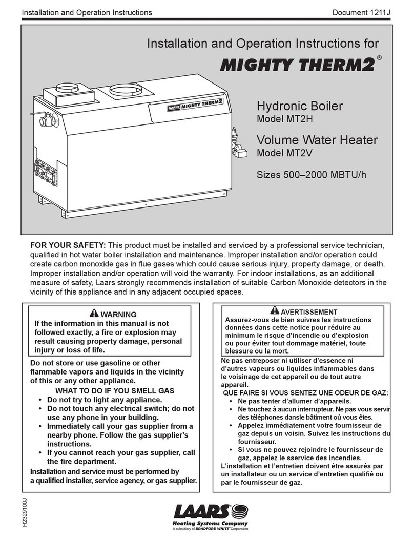
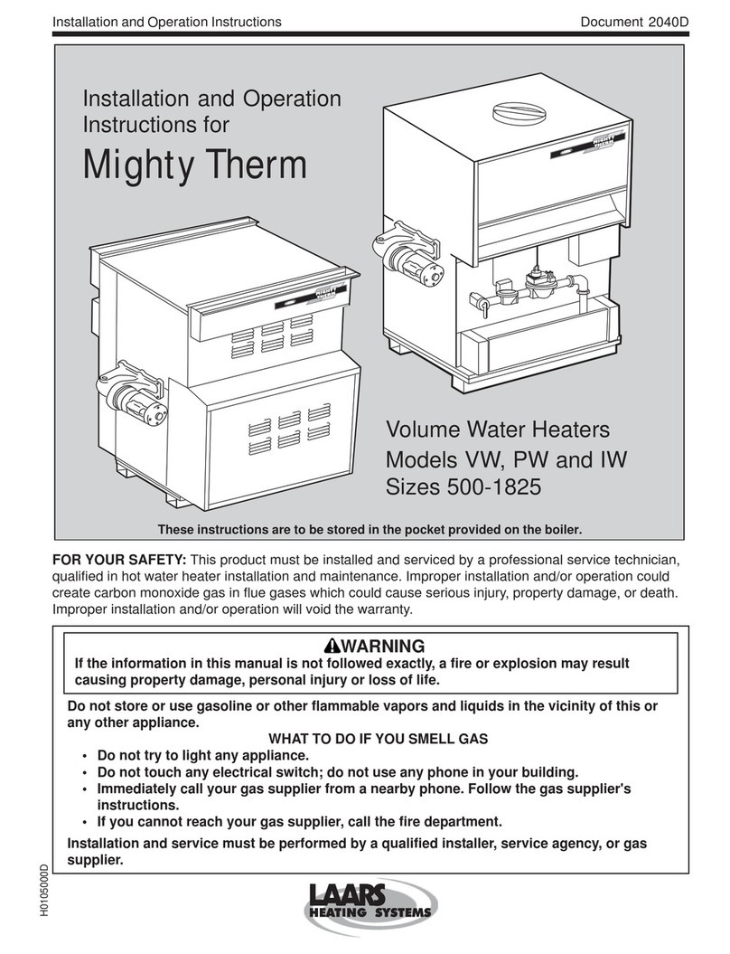
Laars MIGHTY THERM2 Owner's manual

Laars

Laars MIGHTY THERM2 Owner's manual

Laars MCH User manual

Laars

Laars MCH User manual

Laars U.H.E User manual

Laars

Laars U.H.E User manual

Laars HWG-M2-150 Manual

Laars

Laars HWG-M2-150 Manual

Laars VW User manual

Laars

Laars VW User manual

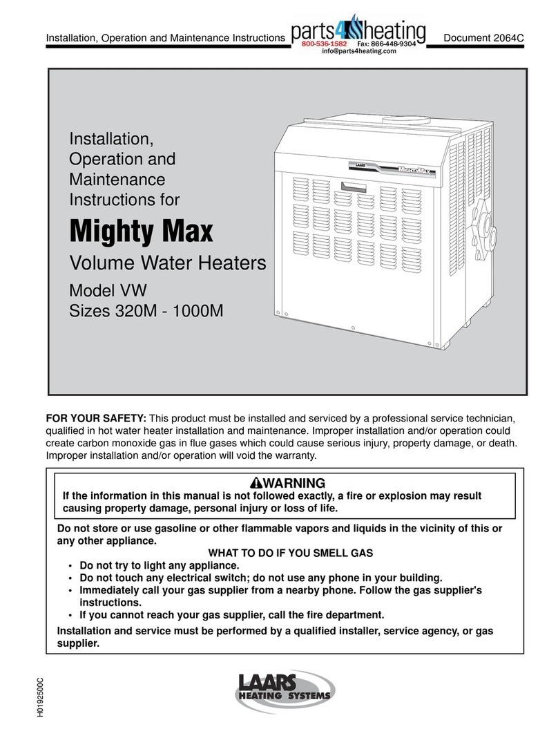
Laars Mighty Max VW Series Manual

Laars

Laars Mighty Max VW Series Manual

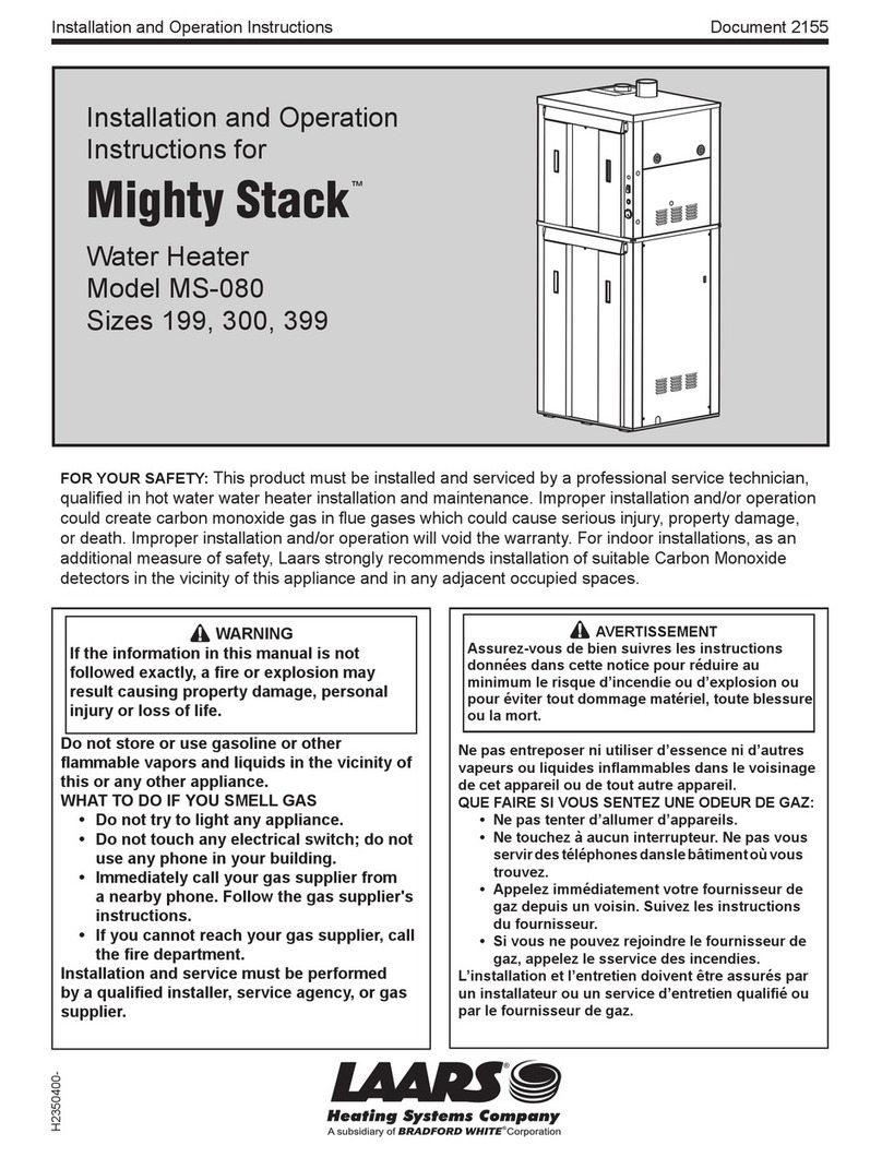
Laars Mighty Stack MS-080 User manual

Laars

Laars Mighty Stack MS-080 User manual

Laars INDIRECT-FIRED User manual

Laars

Laars INDIRECT-FIRED User manual

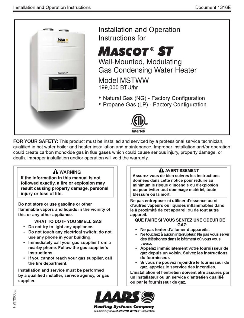
Laars MSTWW199 User manual

Laars

Laars MSTWW199 User manual

Laars Mighty Therm 2 MT2H User manual

Laars

Laars Mighty Therm 2 MT2H User manual
Laars Mighty Max VW User manual

Laars

Laars Mighty Max VW User manual

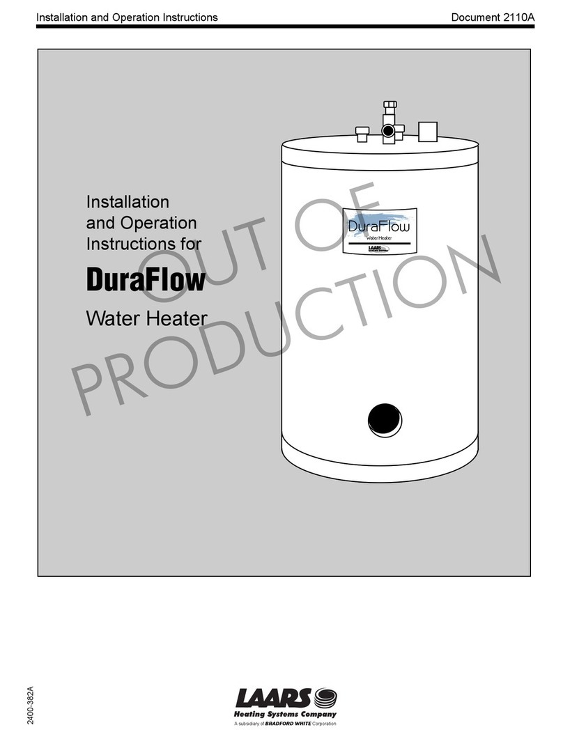
Laars duraflow User manual

Laars

Laars duraflow User manual

Laars LUHE120T User manual

Laars

Laars LUHE120T User manual

Laars 9600 HWG Manual

Laars

Laars 9600 HWG Manual

Laars NEOTHERM NTH User manual

Laars

Laars NEOTHERM NTH User manual
Laars Everhot IGE-199R Series Supplement

Laars

Laars Everhot IGE-199R Series Supplement

Laars VW-PW Manual

Laars

Laars VW-PW Manual

Popular Water Heater manuals by other brands

ApenGroup AX Series Use, Installation and Maintenance Manual

ApenGroup

ApenGroup AX Series Use, Installation and Maintenance Manual

Excelsior GAS-FIRED WATER HEATER Installation & operating instruction manual

Excelsior

Excelsior GAS-FIRED WATER HEATER Installation & operating instruction manual

ThermoFlow Hydrex 18 Mounting and User Manual

ThermoFlow

ThermoFlow Hydrex 18 Mounting and User Manual

Webasto Thermo Top E installation instructions

Webasto

Webasto Thermo Top E installation instructions

Girard Products GSWH-1 installation manual

Girard Products

Girard Products GSWH-1 installation manual

Webasto Thermo Top E Installation documentation

Webasto

Webasto Thermo Top E Installation documentation

GE GeoSpring GT50C10BAM Owner's manual and installation instructions

GE

GE GeoSpring GT50C10BAM Owner's manual and installation instructions

Nibe ES User's and installer's manual

Nibe

Nibe ES User's and installer's manual

Hard Head 021094 operating instructions

Hard Head

Hard Head 021094 operating instructions

A.O. Smith 200 Series Installation

A.O. Smith

A.O. Smith 200 Series Installation

PVI PVI DURAWATT Installation & maintenance manual

PVI

PVI PVI DURAWATT Installation & maintenance manual

Rinnai CU199i Installation and operation manual

Rinnai

Rinnai CU199i Installation and operation manual

JOOLCA HOTTAP V2 user guide

JOOLCA

JOOLCA HOTTAP V2 user guide

Armstrong Flo-Direct installation guide

Armstrong

Armstrong Flo-Direct installation guide

Noritz NRC83-DV Field manual

Noritz

Noritz NRC83-DV Field manual

Danfoss Akva Lux II instructions

Danfoss

Danfoss Akva Lux II instructions

Reliance Water Heaters FVIR C3 instruction manual

Reliance Water Heaters

Reliance Water Heaters FVIR C3 instruction manual

Kenmore Sensor smart electric dryer Quick Start Install Guide

Kenmore

Kenmore Sensor smart electric dryer Quick Start Install Guide

manuals.online logo
manuals.online logoBrands
  • About & Mission
  • Contact us
  • Privacy Policy
  • Terms and Conditions

Copyright 2025 Manuals.Online. All Rights Reserved.