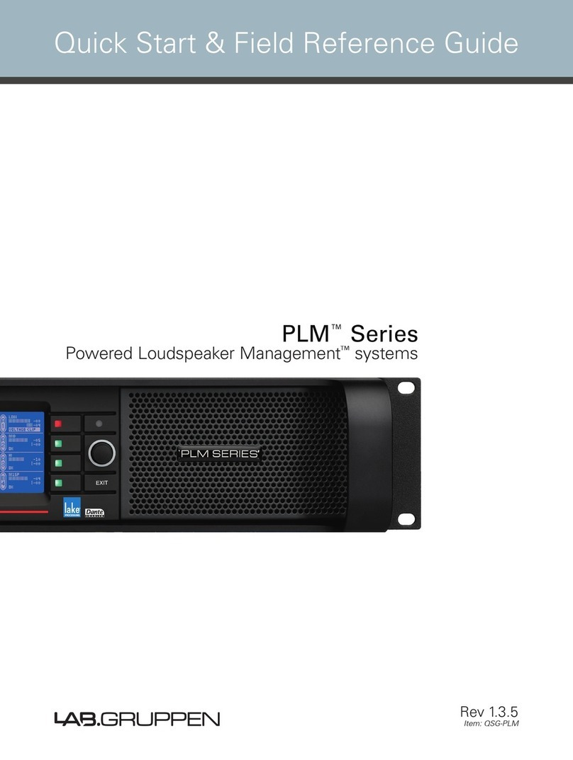
Lab.gruppen PLM Series User manual

Rev. 1.1.3
Item no. OM-PLM
Operation Manual
PLM™Series
Powered Loudspeaker Management™systems
Operation Manual

2 PLM Series Operation Manual rev 1.1.3
Table of Contents
Table of Contents
2. Approvals.....................................................................................................................................................7
3. Warnings...................................................................................................................................................... 7
3.1 Explanation of Graphical Symbols ...........................................................................................................7
3.1.1 WARNING.........................................................................................................................................7
3.1.2 CAUTION..........................................................................................................................................7
3.2 Important Safety Instructions.................................................................................................................. 8
3.3 User Responsibility..................................................................................................................................8
3.3.1 Mains connection grounding ............................................................................................................8
3.3.2 Speaker output hazard .....................................................................................................................8
3.3.3 Radio interference............................................................................................................................9
3.3.4 Speaker damage ..............................................................................................................................9
4. Welcome .................................................................................................................................................... 10
4.1 Introduction ........................................................................................................................................... 10
4.2 Main Features ....................................................................................................................................... 10
4.2.1 Amplier platform........................................................................................................................... 10
4.2.2 Amplier DSP: Gain, ISVPL
™, load verication and performance monitoring................................. 10
4.2.3 Lake®Processing and Controller.................................................................................................... 11
4.2.4 Lake Analyzer Bridge...................................................................................................................... 11
4.2.5 Dante™audio network .................................................................................................................... 11
4.3 Additional Documentation..................................................................................................................... 11
5. Installation................................................................................................................................................. 13
5.1 Unpacking.............................................................................................................................................. 13
5.2 Mounting ............................................................................................................................................... 13
5.3 Rear Mounting....................................................................................................................................... 13
5.4 Cooling .................................................................................................................................................. 15
5.5 Operating Voltage.................................................................................................................................. 15
5.6 Grounding.............................................................................................................................................. 16
6. Quick Guide Overview ............................................................................................................................. 17
6.1 Front Panel Overview ............................................................................................................................ 17
6.2 Rear Panel Overview............................................................................................................................. 19
6.2.1 Input connectors and Links ............................................................................................................20
6.2.2 Output connectors ......................................................................................................................... 21
6.2.3 Network connectors.......................................................................................................................22
6.2.4 AC input .........................................................................................................................................23
6.3 Integrated Lake Processing...................................................................................................................23
6.3.1 Lake Controller software ................................................................................................................23
7. Operation and Performance.....................................................................................................................25
7.1 Introduction to Operation.......................................................................................................................25

PLM Series Operation Manual rev 1.1.3
Table of Contents
3
7.1.1 Operation precautions .....................................................................................................................25
7.2 Power Output Performance ..................................................................................................................25
7.2.1 Symmetrical Power.........................................................................................................................25
7.2.2 Asymmetrical power ......................................................................................................................25
7.2.3 Power over time .............................................................................................................................26
7.3 Amplier and Load Protection Systems ................................................................................................27
7.3.1 Inter-Sample Voltage Peak Limiter (ISVPL).....................................................................................27
7.3.2 Current Peak Limiter (CPL) .............................................................................................................28
7.3.3 Power Average Limiter (PAL) .........................................................................................................28
7.3.4 Current Average Limiter (CAL
™)......................................................................................................29
7.3.5 Voltage Clip Limiter (VCL)...............................................................................................................29
7.3.6 Temperature protection ..................................................................................................................29
7.3.7 DC protection..................................................................................................................................29
7.3.8 VHF protection ...............................................................................................................................30
7.3.9 Short circuit protection ................................................................................................................... 31
7.4 Power Supply......................................................................................................................................... 31
8. Signal Flow and Processing ....................................................................................................................32
8.1 Signal Flow ...........................................................................................................................................32
8.1.1 Level adjustments...........................................................................................................................32
8.1.2 Mute points ....................................................................................................................................33
8.1.3 Power Output Section: Limiting and Sensitivity ............................................................................33
8.3 Modules and Frames ............................................................................................................................35
8.3.1 LoadLibrary™and Fingerprints........................................................................................................36
8.3.2 Super Modules...............................................................................................................................36
8.4 Presets ..................................................................................................................................................37
8.4.1 Module les....................................................................................................................................37
8.4.2 Frame Presets................................................................................................................................37
8.4.3 Subsystem Presets ........................................................................................................................37
8.4.4 System Presets..............................................................................................................................37
9. Front Panel Interface ................................................................................................................................38
9.1 Front Panel Navigation...........................................................................................................................38
9.1.1 General description of navigation in the PLM .................................................................................38
9.1.2 Pinging modules in the Lake Controller software from the PLM ...................................................39
9.2 Key Lock Front Panel.............................................................................................................................39
9.3 Power Button .....................................................................................................................................40
9.4 Mute Enable Button .............................................................................................................................40
9.5 Meter Button ........................................................................................................................................40
9.6 Menu Button .........................................................................................................................................40
9.7 Network Activity LED ........................................................................................................................... 41
9.8 Rotary Encoder ..................................................................................................................................... 41
9.9 Exit Button ...........................................................................................................................................42
9.10 Soft-function buttons ..........................................................................................................................42
9.10.1 Mute functions..............................................................................................................................43
9.10.1.1 PLM Input Mute .....................................................................................................................44
9.10.1.2 Module Input Mute ................................................................................................................44

4 PLM Series Operation Manual rev 1.1.3
Table of Contents
9.10.1.3 Module Output Mute .............................................................................................................44
9.10.1.4 Power Output Mute...............................................................................................................45
9.10.2 LED faults, warnings, and clip indications ....................................................................................45
9.10.2.1 Green indications ................................................................................................................... 47
9.10.2.2 Yellow indications ..................................................................................................................47
9.10.2.3 Red indications ...................................................................................................................... 47
9.11 Warning and Fault Indications..............................................................................................................48
9.12 Meter Mode.........................................................................................................................................49
9.12.2 Meter View 2 – Module View .......................................................................................................52
9.12.3 Meter View 3 – Temperature View...............................................................................................53
9.12.4 Meter View 4 – Input View ..........................................................................................................54
9.13 Meter mode.........................................................................................................................................55
9.13.1 Menu View....................................................................................................................................55
9.13.2 Module submenu .........................................................................................................................56
9.13.2.1 Gain........................................................................................................................................56
9.13.2.3 Phase reverse........................................................................................................................57
9.13.2.4 Amp Gain...............................................................................................................................57
9.13.2.5 Limiters..................................................................................................................................57
9.13.2.5.1 Inter-Sample Voltage Peak Limiter Threshold (ISVPL Threshold) ...................................58
9.13.2.5.2 Inter-Sample Voltage Peak Limiter Prole (ISVPL Prole) ..............................................58
9.13.2.5.3 MaxPeak Level (MaxPeakLvl).........................................................................................58
9.13.2.5.4 MaxRMS Level (MaxRMSLvl) ........................................................................................58
9.13.2.5.5 MaxRMS Corner (MaxRMSCor)....................................................................................58
9.13.2.5.6 MaxRMS Attack (MaxRMSAtk) .....................................................................................58
9.13.2.5.7 MaxRMS Release (MaxRMSRel) ...................................................................................59
9.13.2.6 Mutes ....................................................................................................................................59
9.13.3 Input routing and settings submenu.............................................................................................59
9.13.3.1 Input selection and sensitivity settings..................................................................................60
9.13.3.2 Iso-Float.................................................................................................................................62
9.13.3.3 AES/EBU input termination ...................................................................................................62
9.13.4 Attenuation submenu ...................................................................................................................62
9.13.5 Frame submenu............................................................................................................................63
9.13.5.1 Frame label ............................................................................................................................63
9.13.5.2 Frame Info .............................................................................................................................64
9.13.5.2.1 Firmware version (‘FW version’).....................................................................................64
9.13.5.2.2 Latency (‘Inh. Latency’) ..................................................................................................64
9.13.5.2.3 Max Output Voltage (‘MaxOutVolt’)...............................................................................65
9.13.5.2.4 Max Output Current (‘MaxOutCurr’) ................................................................................65
9.13.5.2.5 Serial Number (‘Serial no.’).............................................................................................65
9.13.5.3 Frame Reset ..........................................................................................................................65
9.13.5.3.1 Factory Reset .................................................................................................................65
9.13.5.3.2 Soft Reset ......................................................................................................................65
9.13.5.4 Network.................................................................................................................................65
9.13.5.4.1 IP Address ......................................................................................................................66
9.13.5.4.2 MAC Address.................................................................................................................66
9.13.5.4.3 Frame ID.........................................................................................................................66
9.13.5.4.4 Network status (‘Online’) ...............................................................................................66
PLM Series Operation Manual rev 1.1.3
Table of Contents
5
9.13.5.4.5 IP Mask ..........................................................................................................................66
9.13.5.5 Latency match .......................................................................................................................66
9.13.5.6 Display adjustments ..............................................................................................................66
9.13.5.6.1 Display Contrast..............................................................................................................66
9.13.5.6.2 Dimming.........................................................................................................................67
9.13.5.6.3 Channel order .................................................................................................................67
9.13.6 Frame Preset submenu ................................................................................................................67
9.13.7 LoadSmart™.................................................................................................................................................................................................................................... 67
9.13.7.1 Congure # of cabinets in parallel ..........................................................................................67
9.13.7.2 LoadSmart verication ...........................................................................................................68
9.13.7.3 Estimated # of Cabinets.............................................................................................................68
9.13.8 Dante ............................................................................................................................................69
9.13.8.1 Using the PLM as a “break-in box” .......................................................................................69
10. Back Panel Interface ...............................................................................................................................70
10.1 Power Inlet...........................................................................................................................................70
10.1.1 PowerCon®wiring details..............................................................................................................70
10.2 Audio Input and Links..........................................................................................................................70
10.2.1 Analog inputs and links.................................................................................................................70
10.2.1.1 Unbalanced operation ............................................................................................................ 71
10.2.1.2 Iso-Float electronic balancing ................................................................................................ 71
10.2.2 Digital inputs and links..................................................................................................................72
10.3 Speaker Output Connections ..............................................................................................................73
10.3.1 Speakon®output connectors ........................................................................................................73
10.3.2 Binding post output connectors ...................................................................................................75
10.4 RJ45 Connectors.................................................................................................................................75
11. Appendix ..................................................................................................................................................77
11.1 Faults and Warnings Overview ............................................................................................................77
11.2 Maintenance ........................................................................................................................................79
11.3 Factory Default Settings ......................................................................................................................79
11.4 Current Draw and Thermal Dissipation Specications.........................................................................80
11.5 Glossary of Terms, Acronyms and Abbreviations ................................................................................82
12. Application Guide ...................................................................................................................................85
12.1 I/O Panels ............................................................................................................................................85
12.2 Power Distribution...............................................................................................................................85
12.3 Gain Structure......................................................................................................................................86
12.3.1 Gain / Level optimization...............................................................................................................87
12.4 Speaker Congurations .......................................................................................................................91
12.5 Digital Audio Interconnections............................................................................................................. 91
12.5.1 AES/EBU interface........................................................................................................................91
12.5.2 System Latency and Delay Compensation...................................................................................92
12.5.3 Connections and cabling ..............................................................................................................92
12.5.3.1 Input and Link connectors .....................................................................................................92
12.5.3.2 Interconnection options.........................................................................................................92
12.5.3.3 Cable types and distance limitations.....................................................................................93

6 PLM Series Operation Manual rev 1.1.3
Table of Contents
12.5.3.4 Signal degradation and loss ..................................................................................................93
12.5.4. External signal distribution hardware ..........................................................................................93
12.5.4.1 Distribution ampliers............................................................................................................93
12.5.4.2 Passive splitters ....................................................................................................................94
12.5.5 Additional reference .....................................................................................................................94
12.6 Digital Clock Conguration ..................................................................................................................95
12.7 Firmware Upgrades .............................................................................................................................96
12.7.1 Firmware upgrades using the update utility ..................................................................................97
12.7.2 Firmware upgrades using the Lake Controller software.............................................................100
12.8 Hot Swapping PLM devices .............................................................................................................. 101
13. Technical Specications....................................................................................................................... 102
14. Warranty ................................................................................................................................................104

PLM Series Operation Manual rev 1.1.3
2. Approvals
7
2. Approvals
This equipment conforms to the requirements of the EMC Directive 2004/108/EC and the requirements of the Low
Voltage Directive 2006/95/EC.
Standards applied: EMC Emission EN55103-1, E3
EMC Immunity EN55103-2, E3, with S/N below 1% at normal operation level.
Electrical Safety EN60065, Class I
This equipment is tested and approved according to the U.S. safety standard ANSI/ UL 60065 and Canadian safety
standard CSA C22.2 NO. 60065. ETL made the tests and they are a Nationally Recognized Testing Laboratory
(NRTL).
3. Warnings
3.1 Explanation of Graphical Symbols
The lightning symbol within a triangle is intended to alert the user to the presence of un-insulated “dangerous voltages”
within the unit’s chassis that may be of sufcient magnitude to constitute a risk of electric shock to humans.
The exclamation point within a triangle is intended to alert the user to presence of important operating and service instruc-
tions in the literature accompanying the product.
3.1.1 WARNING
3.1.2 CAUTION
To reduce the risk of re or electric shock, do not remove screws. No user-serviceable parts inside. Refer servicing to
qualied service personnel
To reduce risk of re or electric shock, do not expose this apparatus to rain or moisture.
Do not expose this system/apparatus to dripping or splashing and ensure that no objects lled with liquids, such as vases,
are placed on the apparatus.
L’appareil ne doit pas être exposé à des egouttements d’eau ou des éclaboussures et de plus qu’aucun objet rempli de
liquide tel que des vases ne doit pas être placé sur l’appareil.
This apparatus must be connected to a mains socket outlet with a protective earthing connection.
Cet appareil doi t être raccordé á une prise de courant qui est branchée à la terre.
The mains plug is used as a disconnect device and shall remain readily operable.
Lorsque la prise du réseau d’alimentation est utilisés comme dispositif de déconnexion, ce dispositif doit demeuré
aisément accessible.

8 PLM Series Operation Manual rev 1.1.3
3. Warnings
3.2 Important Safety Instructions
Before using your PLM, be sure to carefully read the applicable items of this Operation Manual and
the Safety Instructions.
Keep this manual for future reference.1.
Heed all warnings.2.
Follow all instructions.3.
Do not use this unit near water.4.
Do not spill water or other liquids into or on the unit. Do not operate the unit while wet or standing in liquid.5.
Clean only with dry cloth.6.
Do not block the air intake or exhaust ports. Install the unit in accordance with the instructions.7.
Do not operate the unit near heat producing devices such as radiators, heat registers, stoves or other apparatus that produce heat.8.
Always operate the unit with the chassis ground wire connected to the electrical safety earth. Do not defeat the safety purpose of
a grounding-type plug. A grounding-type plug has two pins and a third grounding prong. The third prong is provided for your safety.
If the provided plug does not t into your outlet, consult an electrician for replacement of the obsolete outlet.
Connect only to AC power outlets rated 100-120 V or 200-240 V, 50-60 Hz as dictated by the unit’s voltage conguration.9.
Do not use this unit if the power cord is broken or frayed. Protect the power cord from being walked upon or pinched, particularly10.
at the plug and the point where it exits from the apparatus.
Only use accessories specied by the manufacturer.11.
The unit is intended to use in a 19” rack. Follow the mounting instructions. When a rack on wheels is used, use caution when12.
moving the loaded rack to avoid injury from tipping over.
Unplug this apparatus during lightning storms or when unused for long periods of time.13.
Do not connect the unit’s outputs in parallel or series with any other unit’s output. Do not connect the unit’s output to any other14.
voltage source, such as battery, mains source, or power supply, regardless of whether the unit is turned on or off.
Do not run any of the unit’s outputs back into another channel’s input.15.
Refer all servicing to qualied service personnel. Servicing is required when the apparatus has been damaged in any way such16.
as:
Power-supply cord or plug is damaged.▸
Liquid has been spilled into the unit▸
An object has fallen into the unit▸
The unit has been exposed to rain or moisture▸
The unit does not operate normally▸
The unit was dropped or the chassis is damaged▸
Do not remove top or bottom covers. Removal of the covers will expose hazardous voltages. There are no user serviceable parts▸
inside and removal may void the warranty.
An experienced user shall always supervise this professional audio equipment, especially if inexperienced adults or minors are17.
using the equipment.
The mains plug is used as the disconnect device and shall remain readily accessible. If the mains plug is not readily accessible due18.
to mounting in a 19” rack, then the mains plug for the entire rack must be readily accessible.
The US National Differencescl.16.3 requires that network cables must be ame rated VW-1.19.
3.3 User Responsibility
3.3.1 Mains connection grounding
Your PLM must be connected to a grounded socket outlet.
3.3.2 Speaker output hazard
PLMs are capable of producing hazardous output voltages. To avoid electrical shock, do not touch any
exposed speaker wiring while the PLM is operating. The external wiring connected to the speaker
terminals shall be installed by a qualied person, or ready-made leads or cords of appropriate capacity shall
be used.
As the power output channels produce high voltage, do not connect or disconnect speaker cables
when the mains power is on.

PLM Series Operation Manual rev 1.1.3
3. Warnings
9
3.3.3 Radio interference
A sample of this product has been tested and complies with the limits for the European Electro Magnetic
Compatibility (EMC) directive. This equipment has also been tested and found to comply with the limits for a
Class B digital device, pursuant to Part 15 of the FCC Rules. These limits are designed to provide reasonable
protection against harmful interference from electrical equipment. This product uses radio frequency energy
and if not used or installed in accordance with these operating instructions, may cause interference to other
equipment, such as radio receivers. However, there is no guarantee that interference will not occur in a
particular installation.
If this equipment does cause harmful interference to radio or television reception, which can be determined
by turning the equipment on and off, the user is encouraged to try to correct the interference by one or
more of the following measures:
Reorient or relocate the antenna.▸
Increase the separation between the equipment and receiver.▸
Connect the equipment to an outlet on a circuit different from that to which the receiver is connected.▸
Check if the affected unit complies with the EMC limits for immunity, (CE-labeled). If not, address the▸
problem with the manufacturer or supplier. All electrical products sold in the EC must be approved for
immunity against electromagnetic elds, high voltage ashes, and radio interference.
Consult the dealer or an experienced radio/TV technician for help.▸
3.3.4 Speaker damage
Your PLM Series device is very powerful and can be potentially dangerous to both loudspeakers and
humans alike. Many loudspeakers can be easily damaged or destroyed by overpowering them. Always
check the speaker’s continuous and peak power capabilities. Although the PLM’s attenuators can be used to
reduce the overall gain, an increase of the input signal can result in full output power, which may cause
damage to connected speakers.
3.3.5 Maintenance
For safe and reliable operation, the dust covers behind the front panel should be cleaned regularly. If the
dust lters are not maintained there will be safety risks. For example the unit can ignite the dust and a re
will occur due to high internal temperatures. There is also a risk that the unit will malfunction since it is
dependent on constant airow from front to rear. If the dust lters are not clean and the unit malfunctions,
any resultant problems will not be covered by the warranty.

10
PLM Series Operation Manual rev 1.1.3
4. Welcome
4. Welcome
4.1 Introduction
Thank you for choosing the Lab.gruppen PLM Series of Powered Loudspeaker Management systems for
your sound reinforcement needs. We are condent that you will be pleased with the performance, unique
features, conguration exibility, reliability, and long-term durability offered by PLM Series products.
To facilitate timely installation and use of this PLM Series product, your welcome package includes a printed
copy of the PLM Series Quick Start and Field Reference Guide. It contains the basic information needed to
safely install a PLM system and place it in service. Control and editing features are accessible either via the
intuitive front panel interface or remotely, with the included Lake Controller software package.
We do, however, highly recommend reading through all of the product documentation on the included CD
ROM in its entirety. As you become thoroughly familiar with the many conguration and control options
available in PLM Series products, you may learn about features and options that will affect your choices of
operational modes or loudspeaker system congurations.
Thank you again for placing your condence in Lab.gruppen products.
4.2 Main Features
The PLM Series incorporates a number of sophisticated technologies to ensure the best possible perfor-
mance and many years of reliable operation. The following section summarizes the benets of each feature,
and gives a reference to the corresponding section in this or other manuals.
4.2.1 Amplier platform
The PLM Series power output section is built on the foundation of Lab.gruppen’s robust, road-proven
FP+ Series ampliers. Features in common with the FP+ Series include extraordinary power density,
patented Class TD® output stages, Regulated Switch Mode Power Supply (R.SMPS™), the high-efciency
Intercooler® copper-nned cooling system, and a full suite of protection features. Signal inputs are analog,
AES digital, and Dante digital audio network; loop-through outputs or redundant pairs are provided for each
input type. (See section 6.2.)
4.2.2 Amplier DSP: Gain, ISVPL
™, load verication and performance monitoring
Input gain (sensitivity) is set in the digital domain in the PLM Series, controllable through the Lake Controller
software or the front-panel interface. The DSP-implemented Inter-Sample Voltage Peak Limiter (ISVPL)
tailors each power output to the characteristics of the connected load. (See section 7.3.1.)
The on-board DSP also implements a comprehensive set of proprietary tools developed by Lab.gruppen for
load verication and real-time performance monitoring. These functions utilize LoadLibrary, a comprehensive
database for each loudspeaker component of the connected load (usually one or more band-limited drivers
in a multi-way system). Using this data and a brief test signal, LoadSmart then compares actual response
to predicted response, identifying any malfunctioning components or connection errors. During the actual
performance, SpeakerSafe™ monitors real-time load status, including temperatures of the PLM amplier
stages as well as magnets and voice coils of connected loudspeakers. This allows operators to avoid power

PLM Series Operation Manual rev 1.1.3
4. Welcome
11
compression and identify potential problems. (See the Lake Controller User Manual PLM Addendum for
more detailed information on PLM Series load verication and real-time performance monitoring functions.)
4.2.3 Lake®Processing and Controller
The PLM Series integrates seamlessly into the Lake Processing environment. Two processing modules
offer precise settings for gain, delay, crossover slope, equalization and limiting. Lake processing features
incorporated in each module include Raised Cosine Equalization™, linear phase crossovers, and LimiterMax™
loudspeaker protection. The Super Module feature allows hardware processing modules in two or more
separate PLM Series units to function as a single module in the Lake Controller software interface. (See
section 8.2 and the separate Dolby Lake Controller User Manual.)
4.2.4 Lake Analyzer Bridge
Lake Controller software also allows seamless integration with third-party, real-time sound system measure-
ment tools. This complete integration feature allows you to measure with third-party measurement software
and adjust your system EQ at the same time, using the same user interface.
Third-party measurement tools that can be seamlessly integrated include:
Smaart Version 5▸
Live-Capture Light / Live-Capture Pro▸
Smaart, distributed and supported by EAW, is the most straightforward and widely used software for
real-time sound system measurement, optimization and control. Smaart combines several powerful audio
frequency measurement and analysis tools.
Live-Capture was created by WaveCapture to offer easy-to-use software and measurement tools for sound
engineers, installers, consultants and designers. The Lake Analyzer Bridge in conjunction with Live-Capture
Light provides a completely free spectrum analyzer via your Lake Controller software interface.
4.2.5 Dante™audio network
All PLM Series products include Dante digital audio networking as standard. Based on the latest advances
in networking, Dante offers simplied system conguration and extremely low latency while delivering
very high quality uncompressed digital audio over the entire PLM Series network. The Zen™ automatic
conguration feature enables “plug-and-play” setup without third-party DHCP or DNS servers. Dante is
fully compatible with new high-bandwidth network backbones, allowing high channel counts while also
transporting third-party control protocols through the same network.
4.3 Additional Documentation
This document, the PLM Series Operation Manual, serves as the primary reference source for detailed
information on the installation and operation of PLM Series Powered Loudspeaker Management systems.
It also provides detailed information on set-up and conguration of internal features using the front-panel
interface.
However, if you intend to use the PLM Series unit(s) as part of networked systems, or access monitoring
and control features via the Lake Controller software application, then you may need to refer to the following
complementary documents. All are available on the included CD-ROM or online at:

12 PLM Series Operation Manual rev 1.1.3
4. Welcome
http://www.labgruppen.com/index.php/products/documentation/
PLM Series Quick Start and Field Reference Guide – This document provides basic information needed to
unpack, install, and access basic feature sets of the PLM Series. A printed copy is included with your unit.
PLM Series Network Conguration Guide – This document provides detailed information on creating net-
works of PLM Series units, with sample network topologies and specic recommendations for third-party
networking devices.
Lake Controller User Manual PLM Addendum – This document covers those features and functions that are
unique to the PLM in the Lake Controller software application.
Dolby Lake Controller User Manual – This document provides detailed information on features and functions
of Dolby Lake Controller exclusive of features unique to the PLM Series. It is available both on the included
CD-ROM or via download at:
http://www.labgruppen.com/index.php/products/documentation/.

PLM Series Operation Manual rev 1.1.3
5. Installation
13
5. Installation
5.1 Unpacking
Carefully open the shipping carton and check for any damage to the PLM Series product or the supplied
accessories. Every Lab.gruppen product is tested and inspected before leaving the factory and should arrive
in perfect condition. If any damage is discovered, please notify the shipping company immediately. Only the
consignee may initiate a claim with the carrier or their insurers for damage incurred during shipping. Save
the carton and packing materials for the carrier’s inspection.
In addition to the PLM, the shipping carton include the following items:
PLM Series Quick Start and Field Reference Guide▸
AC mains lead (power cord)▸
Rear brackets for additional rack support (pair)▸
Mounting hardware for above▸
CD-ROM containing:▸
Lake Controller software and rmware▸
Release Notes▸
Dolby Lake Controller User Manual▸
Lake Controller User Manual PLM Addendum▸
PLM Series Operation Manual▸
PLM 10000Q Current Draw and Thermal Dissipation▸
PLM Series Network Conguration Guide▸
PLM 10000Q Technical Data▸
PLM 14000 Technical Data▸
PLM 10000Q A&E Specications▸
We recommend that you keep the original carton and all other packaging materials to facilitate shipping of
the PLM should the need arise.
5.2 Mounting
Airow for cooling the PLM is from front panel (intake) to rear panel (exit). There must be nothing at the front
or rear of the rack in which the PLM is mounted – such as doors or lids - to impede the airow.
Note that there must always be sufcient space at the rear of the PLM to permit efcient air exit (see
section 5.4) and to accommodate rear connectors and cables; allowance must be made for cable or loom
bends within a rack. In particular, the mains cable (AC cord) and its Neutrik®PowerCon connector require at
least 120 mm (4.75 inches) clear rack depth behind the PLM rear panel. The PLM Series products have no
top or bottom vents; PLM’s may be stacked directly on top of each other. It may be desirable to include a 1U
spacer between PLMs to permit more convenient rear panel wiring.
5.3 Rear Mounting
Two rear support brackets, plus mounting hardware, are included with the PLM (gure 5.3a). It is recom-
mended that these are used wherever possible. They should be tted to vertical rack rails at the rear of the
rack. Refer to gures 5.3b and 5.3c for details of their installation.

14 PLM Series Operation Manual rev 1.1.3
5. Installation
Note that the support brackets are reversible and may be tted to point either to the front or rear of the rack.
The orientation used in a particular situation will depend on the depth of the rack and the position of the rear
rack rails.
Two mounting methods are possible; note that the method shown in gure 5.3b additionally provides extra
security against unauthorized removal.
For situations where rapid removal and replacement of units is of paramount importance, the method shown
in gure 5.3c may be used as it does not involve any permanently secured xing at the rear of the unit.
x2
x2 x2x2
Figure 5.3a: Rear support mounting hardware Figure 5.3c: Use tube for slide-on installation
Figure 5.3b: Use washer for xed installation

PLM Series Operation Manual rev 1.1.3
5. Installation
15
5.4 Cooling
The PLM uses a forced-air cooling system with airow from front to rear, allowing high continuous power
levels without thermal problems. (Front-to-rear airow is preferable as air at the front of a rack is cooler
than that at the rear in nearly all situations.) Never attempt to reverse the airow. The operation of the
PLM’s cooling system is dependent on front-to-rear airow; it will not function effectively with airow in the
opposite direction.
Make sure an adequate air supply is provided in front of the PLM, and that the rear of the PLM has sufcient
space to allow the exit air to escape. If the PLM is rack-mounted, never operate the unit with any front or
rear rack doors or covers in position. Also note that any unused rack spaces should have solid blanks tted
(not ventilation blanks) to ensure efcient air circulation. Leaving gaps in between items of equipment
degrades the effectiveness of forced-air cooling.
If installing one or more PLM units in a rack with other fan-cooled equipment, be sure that all the other units
also use front-to-rear airow for cooling. If this precaution is not observed, there is a risk of overheating, as
units with the reverse airow will be drawing in air which has already been heated by the PLMs.
The PLM is equipped with a sophisticated tempera-
ture sensing system which protects it from any
overheating which may occur as a result of
inadequate ventillation. Should a power output
channel overheat, the temperature sensing circuits will mute
that channel until the temperature reduces to a safe level. If the
power supply overheats, another sensing circuit will mute will
reduce the overall output level of all channels in an effort to
bring the PSU temperature down. If a problem still exists, a
sensing circuit will mute the power output channel that has the
highest temperature reading, thereby reducing the overall
temperature of the power supply until it reduces to a safe
operating level.
Always make sure that the dust lters behind the detachable front panel are clean to ensure maximum
possible airow.
5.5 Operating Voltage
The label adjacent to the mains (AC) input connector indicates the AC mains voltage for which the
amplier is wired and approved. The amplier is built in two versions: 115 V and 230 V. Connect the
mains cable (AC cord) only to an AC source of the voltage shown on the label.
Any damage resulting from a PLM Series product
being connected to an AC source of incorrect
voltage will not be covered by the warranty.

16 PLM Series Operation Manual rev 1.1.3
5. Installation
The PLM uses primary switching, which means the mains power is rectied on the primary side of the
transformer. This makes the power supply insensitive to mains frequency variation, and it will operate
normally on line frequencies from 45 to 75 Hz.
If the mains plug (AC plug) tted to the mains cable (AC cord) is not appropriate for your country, it can be
removed and a locally-sourced one tted instead, observing the color coding in the table below:
PowerCon Pin 230 V Version 115 V Version
LBrown Black
NBlue White
Green/Yellow Green
Table 5.5: AC plug conguration
If you are not 100% condent of your competence to replace the mains plug (AC plug), the task should
be carried out by qualied personnel.
Once a suitable AC supply is connected, the PLM can be turned on using the front panel power switch.
When the unit is switched on, the PLM goes through a soft-start sequence as it performs a diagnostic
routine on the internal circuitry. The fans will run at high speed for a short period before dropping to idle
speed, and the power symbol in the power switch will change from red (Standby mode) to green (active).
5.6 Grounding
Analog inputs feature Iso-Float™ground isolation, a technology which combines the benets of transformer-
coupled isolation with the advantages of clean, direct-coupled inputs.
The audio converters are galvanically isolated, and not connected to the main ground. High-speed transform-
ers and opto-isolators create a barrier between the PLM and the outside electrical environment.
In the interests of safety, NEVER disconnect the earth (ground) pin on the mains cable (AC power cord).
Use correctly-shielded balanced audio input connections to minimise hum and interference. Refer to section
10.2.1 for more information.
In-rush current is controlled and limited during the
soft-start sequence, enabling multiple PLMs on the
same AC mains circuit to be powered up simultane-
ously.
The Iso-Float feature is activated by default, but
may be disabled via the supplied Lake Controller
software, or via the PLM’s front panel menu system.

PLM Series Operation Manual rev 1.1.3
6. Quick Guide Overview
17
6. Quick Guide Overview
PLM SERIES
3
4
5
67
8
9
10 11
12
1 1
2 2
Figure 6.1: PLM front panel layout
6.1 Front Panel Overview
The front panel controls, clustered around a 2.5” daylight readable LCD, perform most control and
monitoring functions via a simple menu system. The two switch clusters on either side of the LCD include
dedicated function keys as well as eight “soft keys” (functions vary according to current display page) and a
rotary data encoder.
Handles
Two sturdy metal handles are tted to the front panel. The handles always should be used when carrying
the PLM, and when tting it in or removing it from a rack. Ensure that any door or removable rack front
cover has sufcient depth to clear the handles.
Dust lters
Two dust lters are tted behind metal covers. To remove the covers, loosen the thumbscrews located
behind the handles. Once detached, the dust lter elements can be removed for cleaning. See section 11.2
for information on cleaning the dust lters.
Display
The display illuminates when the PLM is active. Many of the control and metering functions found on
conventional ampliers are replaced on the PLM by a set of on-screen pages which, together with the soft
keys and rotary encoder, allow monitoring and control of operating parameters. Multicolor LEDs embedded
in the soft keys display fault and warning status indications.
The layout of various display “pages” is standardized to a high degree for ease of use. In general, each page
is divided into two columns of four blocks, with the left-hand column referring to inputs and the right-hand
to outputs. Each block has four rows of data, which can be either alphanumeric or in the form of a bargraph
meter.
The device never should be operated without the
dust lters in place.

18 PLM Series Operation Manual rev 1.1.3
6. Quick Guide Overview
The brightness of the display and the adjoining network activity LED can be adjusted in the Frame page of
the Main menu.
Comprehensive details of the various display pages and the associated controls are given in section 9 –
Front Panel Interface.
Standby
The PLM is powered on and off by the top left-most button, STANDBY. See Lake Controller User Manual
PLM Addendum (sections 5.3.1 and 5.7) for further information regarding local and remote power control.
Mute Enable
Select MUTE ENABLE to allow muting via the soft function buttons of the inputs to the Lake system,
the power output channels, or both. The MUTE ENABLE legend in the button ashes when the mode is
selected. A second press will deselect the mode; however, if left active, MUTE ENABLE mode will auto-
matically cancel after two minutes if no further mute actions are taken.
Meter
The METER button scrolls through four alternative views: HOME, MODULE, TEMPERATURE and INPUT.
Pressing METER when in MENU mode returns the screen to METER mode, and the HOME view is
displayed.
Menu
Pressing the MENU button puts the screen display into MENU mode, and the “top” page of the MENU
“tree” is displayed. Once in MENU mode, the function buttons enable the user to navigate the menu tree
and access most PLM Series operating functions. See sections 9.12.2 to 9.12.8 for more details.
Soft Function Buttons
Eight soft function buttons are set adjacent to the display in two groups of four. These buttons are unlabelled
because their functions change according to the current menu mode as displayed on the screen. In MENU
mode they are used to navigate the menu tree and for the selection of parameters to edit. In METER mode
they will act in conjunction with the MUTE ENABLE feature.
Status LEDs
Eight tricolor LEDs are integrated into the soft function buttons for convenience. These convey both fault
and warning indications, plus the currently selected mute status of the Lake Processing system inputs and
the output channels. Full details can be found in section 9.10.
High-intensity LED
A white, high-intensity LED is located to the right of the display. This LED illuminates when the PLM Series’
control system is being accessed remotely via the Lake Controller software. Steady illumination of the white
LED indicates that the unit is selected in the Lake Controller software; a ashing white LED indicates a change
in parameters or operating state.
The display has two basic operating modes: METER
(default) and MENU.

PLM Series Operation Manual rev 1.1.3
6. Quick Guide Overview
19
The brightness of the display and the adjoining network activity LED can be adjusted in the Frame page of
the Main menu.
Encoder
The rotary encoder is used to modify various PLM parameters (e.g. input level) in the leaf nodes of the
menu tree. When a menu item is selected that permits adjustment of parameter values, the ring around the
knob illuminates. While in HOME view the encoder can also be used to scroll through the different meter
views.
Exit
The EXIT key is used primarily while navigating the menu system in MENU mode; pressing it takes the
display back to a previous screen (“up one level” in the menu tree). In METER mode, pressing the EXIT key
always returns the display to the HOME view.
6.2 Rear Panel Overview
Ser. N:o
Removed!
CH 2
CH
1
CH 4
CH 3
CLASS 2 WIRING
SPEAKER OUTPUTS
INPUT
1
INPUT 2LINK
1
LINK 2
AES/EBU
INPUT 1-2 LINK 1-2
LINK SECPRIMACT LINKACT
SWITCHED 10/100 Base-TX
Must be grounded/earthed
Made in Sweden
PIN 1: SCRN 2: POS 3: NEG
ANALOG WITH
I
SO-
F
LOAT
TM
200-240V 2500W
50-60Hz
PLM
0000Q1
Ser. N:o
Removed!
CLASS 2 WIRING
SPEAKER OUTPUTS
INPUT
1
INPUT 2LINK
1
LINK 2
AES/EBU
INPUT 1-2 LINK 1-2
LINK SECPRIMACT LINKACT
SWITCHED 10/100 Base-TX
Must be grounded/earthed
Made in Sweden
PIN 1: SCRN 2: POS 3: NEG
ANALOG WITH
I
SO-
F
LOAT
TM
1+/- CH 1+/-
2+/- CH 2+/-
1+/- CH 1+/-
2+/- CH 2+/-
3+/- CH 3+/-
4+/- CH 4+/-
1+/- CH 3+/-
2+/- CH 4+/-
200-240V 2500W
50-60Hz
PLM
0000Q
1
1234
5
6
7 8 9
12
Figure 6.2a: 4-channel PLM rear panel layout

20
PLM Series Operation Manual rev 1.1.3
6. Quick Guide Overview
Ser. N:o
Removed!
SPEAKER OUTPUTS
INPUT
1
INPUT 2LINK
1
LINK 2
AES/EBU
INPUT 1-2 LINK 1-2
LINK SECPRIMACT LINKACT
SWITCHED 10/100 Base-TX
Must be grounded/earthed
Made in Sweden
PIN 1: SCRN 2: POS 3: NEG
ANALOG WITH
I
SO-
F
LOAT
TM
CH
1
CH
1
CH 2
CH 2
CLASS 3 WIRING
50-60Hz
PLM
40001
200-240V 2950W
INPUT
1
INPUT 2LINK
1
LINK 2
AES/EBU
INPUT 1-2 LINK 1-2
LINK SECPRIMACT LINKACT
SWITCHED 10/100 Base-TX
Must be grounded/earthed
Made in Sweden
PIN 1: SCRN 2: POS 3: NEG
ANALOG WITH
I
SO-
F
LOAT
TM
Ser. N:o
Removed!
CLASS 3 WIRING
SPEAKER OUTPUTS
1+/- CH 1+/-
2+/- CH 2+/-
1+/- CH 2+/-
2+/- CH 1+/-
50-60Hz
PLM
40001
200-240V 2950W
1234
5
6
7 8 9
12
Figure 6.2b: 2-channel PLM rear panel layout
6.2.1 Input connectors and Links
Analog inputs
Analog inputs are available on two standard XLR3F latching connectors. The inputs are electronically
balanced and feature Lake Iso-Float circuitry. The impedance is 20 kOhms, and the inputs can accept a
maximum input level of +26 dBu.
Analog links
Two latching XLR3M connectors are tted adjacent to the analog input connectors. These are paralleled to
the input connectors to provide an unprocessed analog loop-through to feed additional PLM Series units, or
other equipment.
AES/EBU inputs
A latching XLR3F connector is provided which accepts an AES/EBU digital audio signal. Input
impedance is 110 ohms.
In comparison to analog signals, digital audio
signals such as AES/EBU require quite different
cabling and routing techniques. In particular,
standard XLR “mic cables” - even high-quality
ones - are rarely suitable for digital audio. Always use 110
ohm digital audio cables. See sections 10.2.2 and 12.5 for
further information before making any connections to the
AES/EBU inputs.
The AES/EBU digital audio format is two-channel,
and thus both PLM inputs are fed via a single
connector. Selection of the analog or digital inputs is
made via the front panel display or control software.
See section 10 for full details of connector pinouts,
etc.
Other manuals for PLM Series
7
This manual suits for next models
2
Table of contents
Other Lab.gruppen Recording Equipment manuals

Lab.gruppen
Lab.gruppen PLM Series User manual

Lab.gruppen
Lab.gruppen PLM 20K44 User manual

Lab.gruppen
Lab.gruppen PLM Series User manual

Lab.gruppen
Lab.gruppen PLM Series User manual

Lab.gruppen
Lab.gruppen PLM Series User manual

Lab.gruppen
Lab.gruppen PLM Series User manual

Lab.gruppen
Lab.gruppen PLM Series User manual

Lab.gruppen
Lab.gruppen PLM Series User manual

Lab.gruppen
Lab.gruppen PLM 20K44 User manual