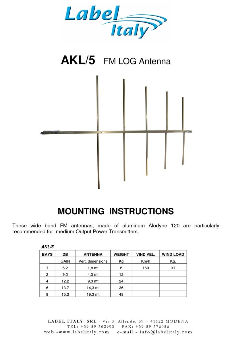
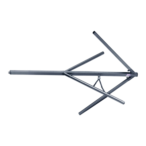
Label Italy Dipole User manual

------------------------------------------------------------------------------------------------------
L A B E L I T A L Y S R L - V i a S . A l l e n d e , 5 9 – 4 1 1 2 2 M O D E N A
T E L : 0 5 9 / 3 6 2 9 9 3 A X : 0 5 9 / 3 7 6 0 5 6
P . I V A 0 2 5 7 8 7 5 0 3 6 2 C a p i t a l e S o c i a l e 3 2 . 5 0 0 E u r o
w e b - ww w . la b e l i t a ly . c o m e - ma i l - i n fo @ l a b e l it a l y. c o m
GENERAL RULES
•
FM BROADBAND ANTENNAS
( Dipole, Yagi, Panel, Circular),
•VHF-UHF-SHF ANTENNAS
( Corner, Yagi, Parabols from 200 Mhz to 2,5 Ghz),
•FM STAR TYPE COMBINERS
•FM DOUBLE BRIDGE COMBINERS
•COAXIAL CAVITIES AND NOTCH
•POWER SPLITTERS
•HYBRID COUPLERS
•DIRECTIONAL COUPLERS
•CABLES, CONNECTORS AND ADAPTERS
•INSTALLATION ACCESSORIES

2
------------------------------------------------------------------------------------------------------
L A B E L I T A L Y S R L - V i a S . A l l e n d e , 5 9 – 4 1 1 2 2 M O D E N A
T E L : 0 5 9 / 3 6 2 9 9 3 A X : 0 5 9 / 3 7 6 0 5 6
P . I V A 0 2 5 7 8 7 5 0 3 6 2 C a p i t a l e S o c i a l e 3 2 . 5 0 0 E u r o
w e b - ww w . la b e l i t a ly . c o m e - ma i l - i n fo @ l a b e l it a l y. c o m
WARRANTY
Label Italy Srl warrants each new product manufactured to be free from defects in material and
workmanship and agrees to remedy any such defect, or to furnish a new part, in exchange for any
part of any unit which under normal installation, use, and service discloses such defect within 1
year from the date of purchase by original owner. This warranty does not extend to any of our
products which have been subjected to misuse neglect, accident, incorrect wiring, improper
installation or to use in violation of instruction furnished by us. Nor does it extend to units which
have been repaired or altered outside of our factory nor to accessories used therewith not of our
own manufacture. Label Italy reserves the right to make any changes deemed necessary or
desirable without advance notice incurring any obligation to make like changes in units previously
manufactured or sold. This warranty does not cover transportation or installation cost that may be
incurred. Label Italy’s sole liability is the remedy of any defect for 1 year. Label Italy is not
responsible for personal injury or property damage resulting from improper or careless installation
or usage not intended by the manufacturer. No person is authorized to assume for us any other
liability in connection with the sale of our product. You must furnish model code, serial number,
date, place and proof of purchase. Such as a copy of the sales receipt to establish warranty. Your
letter should include all pertinent details along with part or item serial number involved. Do not
return anything until requested to do so.
WARNING
When energized by an RF transmitter, this antenna system will present a high intensity R.F. field.
Care should be taken not to touch the antenna system when energized unless performing touch
test under factory supervision. It is not advisable to remain near the antenna for extended periods
of time while the antenna system is energized. All the maintenance or repairs should be done with
the transmitter switched off . If the antenna is not pressurized, condensation can occur inside the
antenna harness resulting in possible failure of the antenna.
LIGHTNINGS - ORIGINS AND PROTECTION CRITERIA
The violent and timely atmospheric perturbations, in which electrical phenomena are involved,
such a lighting strokes, have an important influence on the choice of the site in which the
transmitting station will be created. In the low part of the clouds, there is an important quantity of
negative loads, while in the upper part there is the same quantity of positive loads. When the
ionization of the surrounding air reaches some critical values in the low part of the cloud, a
discharge towards the earth is developed, and determines an elevating counter-discharge that will
intercept the descending discharge. The ground draining of the electrical loads enable the passage
of a current pulse that goes from a value of a few KA to several thousands of KA with an intense
electrical field that reaches 300.000 Volt/m: such a passage represents the visible part of the
lightning stroke, which can be one Km long if the discharge happens between the cloud and the
earth. On very high structures, especially if they are situated in dominating positions such as radio
and television transmitting installations, during the storm perturbations some over-tensions that
create real elevating discharges can be observed.
One must keep in mind that during the discharge phenomenon there can be some clouds which
are electrically loaded and which have not already found their discharge channel ; these positions
consist of materials that are good electric conductors and that because of its nature the lightning
stroke chooses the way that presents the lowest electrical resistance.
One realizes the importance and delicateness of the problem and the resolution of the lightning
themselves. The lightings phenomenon depends much on probability, and as a consequence, one
can never have the absolute and guaranteed certainty to be protected. One should not protect all
the positions without any discrimination, but protect the positions that could be touched more easily
in reason of the geographical characteristics of the terrain.

3
------------------------------------------------------------------------------------------------------
L A B E L I T A L Y S R L - V i a S . A l l e n d e , 5 9 – 4 1 1 2 2 M O D E N A
T E L : 0 5 9 / 3 6 2 9 9 3 A X : 0 5 9 / 3 7 6 0 5 6
P . I V A 0 2 5 7 8 7 5 0 3 6 2 C a p i t a l e S o c i a l e 3 2 . 5 0 0 E u r o
w e b - ww w . la b e l i t a ly . c o m e - ma i l - i n fo @ l a b e l it a l y. c o m
The most important and preferred criteria that must
be followed for the protection of the radio electrical
stations are normally the following:
1) Creation of a valid grounding system for the
whole site, this system must have a low resistance
value of discharge dispersion.
2) Shielding of all the electrical and radio electrical
circuits after the supply transformation.
3) Superposition of opportune voltage limiters in the
connection points between the screened and non-
screened circuits including the isolation of such
circuits.
The antenna tower, the equipment room, but also
the transformation box must be connected to the
same grounding system.
Such system must be designed and built in such way that it guarantees the major and uniform
equipotentiality between the different parts. Moreover, the resistance value of discharge dispersion
must be low enough. As far as material is concerned, one can use both copper or zinc-plated steel
under the form of cords or plaits but copper is more resistant to corrosion. In order to avoid more
risk, one can install some isolation transformers in the supply network. One must pay particular
attention to the dispersor, which is directly connected to the antenna tower which is encharged of
dispersing almost all the lightning current to the ground. The dispersor can be either vertical
(pickets) or horizontal (rings or nets), depending on the resistivity of the terrain.
Finally, it will be necessary to link the metallic
fence to the general grounding system, while the
distance between such fence and the dispersors of
the system shall not exceed 5 meters. One should
remember that in order to have a more efficient
shielding, the screens of the cables and the metallic
sheaths must be grounded at both ends. All the
grounding connections must have a short and
rectilinear path and have multiple interconnections.
To conclude, the lightning stroke generally touches
the antenna tower that carries the radiating
antennas.
In order to avoid serious damages it is necessary that the antennas are situated with large margin,
within the protection cone of the tower. Otherwise it is indispensable to install metallic rods that
pick-up the discharges to the top of the tower connected to it with a good electrical contact.
POLARISATION
The Polarisation is an important factor for RF antennas and radio communications in general. Both
RF antennas and electromagnetic waves are said to have a polarization. For the electromagnetic
wave the polarization is effectively the plane in which the electric wave vibrates. This is important
when looking at antennas because they are sensitive to polarisation and generally only receive or
transmit a signal with a particular polarization. For most antennas it is very easy to determine the
polarization. It is simply in the same plane as the elements of the antenna. So a vertical antenna
(i.e. one with vertical elements) will receive vertically polarised signals best and similarly a
horizontal antenna will receive horizontally polarised signals.

4
------------------------------------------------------------------------------------------------------
L A B E L I T A L Y S R L - V i a S . A l l e n d e , 5 9 – 4 1 1 2 2 M O D E N A
T E L : 0 5 9 / 3 6 2 9 9 3 A X : 0 5 9 / 3 7 6 0 5 6
P . I V A 0 2 5 7 8 7 5 0 3 6 2 C a p i t a l e S o c i a l e 3 2 . 5 0 0 E u r o
w e b - ww w . la b e l i t a ly . c o m e - ma i l - i n fo @ l a b e l it a l y. c o m
An electromagnetic wave
It is important to match the polarization of the RF antenna to that of the incoming signal. In this way
the maximum signal is obtained. If the RF antenna polarization does not match that of the signal
there is a corresponding decrease in the level of the signal. It is reduced by a factor of cosine of
the angle between the polarisation of the RF antenna and the signal. Accordingly the polarisation
of the antennas located in free space is very important, and obviously they should be in exactly the
same plane to provide the optimum signal. If they were at right angles to one another (i.e. cross-
polarised) then in theory no signal would be received. For terrestrial radio communications
applications it is found that once a signal has been transmitted then its polarisation will remain
broadly the same. However reflections from objects in the path can change the polarisation. As
the received signal is the sum of the direct signal plus a number of reflected signals the overall
polarisation of the signal can change slightly although it remains broadly the same.
POLARISATION CATEGORIES
Vertical and horizontal are the simplest forms of antenna polarization and they both fall into a
category known as linear polarisation. However it is also possible to use circular polarisation.
Circular polarisation can be seen to be either right or left handed dependent upon the direction of
rotation as seen from the transmitter. Another form of polarisation is known as elliptical
polarisation. It occurs when there is a mix of linear and circular polarisation. However it is possible
for linearly polarised antennas to receive circularly polarised signals and vice versa. The strength
will be equal whether the linearly polarised antenna is mounted vertically, horizontally or in any
other plane but directed towards the arriving signal.
There will be some degradation because the signal level will be 3 dB less than if a circularly
polarised antenna of the same sense was used. The same situation exists when a circularly
polarised antenna receives a linearly polarised signal.
APPLICATIONS OF ANTENNA POLARISATION
Different types of polarisation are used in different applications to enable their advantages to be
used. Linear polarization is by far the most widely used for most radio communications
applications. Vertical polarisation is often used for mobile radio communications. This is because
many vertically polarized antenna designs have an omni-directional radiation pattern and it means
that the antennas do not have to be re-orientated as positions as always happens for mobile radio
communications as the vehicle moves. For other radio communications applications the
polarisation is often determined by the RF antenna considerations. Some large multi-element
antenna arrays can be mounted in a horizontal plane more easily than in the vertical plane. This is
because the RF antenna elements are at right angles to the vertical tower of pole on which they
are mounted and therefore by using an antenna with horizontal elements there is less physical and
electrical interference between the two. This determines the standard polarisation in many cases.

5
------------------------------------------------------------------------------------------------------
L A B E L I T A L Y S R L - V i a S . A l l e n d e , 5 9 – 4 1 1 2 2 M O D E N A
T E L : 0 5 9 / 3 6 2 9 9 3 A X : 0 5 9 / 3 7 6 0 5 6
P . I V A 0 2 5 7 8 7 5 0 3 6 2 C a p i t a l e S o c i a l e 3 2 . 5 0 0 E u r o
w e b - ww w . la b e l i t a ly . c o m e - ma i l - i n fo @ l a b e l it a l y. c o m
In some applications there are performance differences between horizontal and vertical
polarization. For example medium wave broadcast stations generally use vertical polarisation
because ground wave propagation over the earth is considerably better using vertical polarization,
whereas horizontal polarization shows a marginal improvement for long distance communications
using the ionosphere. Circular polarisation is sometimes used for satellite radio communications as
there are some advantages in terms of propagation and in overcoming the fading caused if the
satellite is changing its orientation.
DIRECTIVITY
the aerials do not radiate equally in all directions. It is found that any realizable RF antenna design
will radiate more in some directions than others. The actual pattern is dependent upon the type of
antenna design, its size, the environment and a variety of other factors. This directional pattern can
be used to ensure that the power radiated is focused in the desired directions. It is normal to refer
to the directional patterns and gain in terms of the transmitted signal. It is often easier to visualize
the RF antenna is terms of its radiated power, however the antenna performs in an exactly
equivalent manner for reception, having identical figures and specifications. In order to visualize
the way in which an antenna radiates a diagram known as a polar diagram is used. This is
normally a two dimensional plot around an antenna showing the intensity of the radiation at each
point for a particular plane. Normally the scale that is used is logarithmic so that the differences
can be conveniently seen on the plot. Although the radiation pattern of the antenna varies in three
dimensions, it is normal to make a plot in a particular plane, normally either horizontal or vertical as
these are the two that are most used, and it simplifies the measurements and presentation. An
example for a simple horizontal polarization dipole antenna is shown below.
Polar diagram of a half wave dipole in free space
Antenna designs are often categorized by the type of polar diagram they exhibit. For example an
omni-directional antenna design is one which radiates equally (or approximately equally) in all
directions in the plane of interest. An antenna design that radiates equally in all directions in all
planes is called an isotropic antenna. As already mentioned it is not possible to produce one of
these in reality, but it is useful as a theoretical reference for some measurements. Other RF
antennas exhibit highly directional patterns and these may be utilized in a number of applications.
The Yagi antenna is an example of a directive antenna and possibly it is most widely used for
many applications.

6
------------------------------------------------------------------------------------------------------
L A B E L I T A L Y S R L - V i a S . A l l e n d e , 5 9 – 4 1 1 2 2 M O D E N A
T E L : 0 5 9 / 3 6 2 9 9 3 A X : 0 5 9 / 3 7 6 0 5 6
P . I V A 0 2 5 7 8 7 5 0 3 6 2 C a p i t a l e S o c i a l e 3 2 . 5 0 0 E u r o
w e b - ww w . la b e l i t a ly . c o m e - ma i l - i n fo @ l a b e l it a l y. c o m
Polar diagram for a yagi antenna
RF ANTENNA BEAM WIDTH
There are a number of key features that can be seen from this polar diagram. The first is that there
is a main beam or lobe and a number of minor lobes. It is often useful to define the beam-width of
an RF antenna. This is taken to be angle between the two points where the power falls to half its
maximum level, and as a result it is sometimes called the half power beam-width.
ANTENNA GAIN
An RF antenna radiates a given amount of power. This is the power dissipated in the radiation
resistance of the RF antenna. An isotropic radiator will distribute this power equally in all directions.
For an antenna with a directional pattern, less power will be radiated in some directions and more
in others. The fact that more power is radiated in given directions implies that it can be considered
to have a gain. The gain can be defined as a ratio of the signal transmitted in the "maximum"
direction to that of a standard or reference antenna. This may sometimes be called the "forward
gain". The figure that is obtained is then normally expressed in decibels (dB). In theory the
standard antenna could be almost anything but two types are generally used. The most common
type is a simple dipole as it is easily available and it is the basis of many other types of antenna. In
this case the gain is often expressed as dBd i.e. gain expressed in decibels over a dipole. However
a dipole does not radiated equally in all directions in all planes and so an isotropic source is
sometimes used. In this case the gain may be specified in dBi i.e. gain in decibels over an isotropic
source. The main drawback with using an isotropic source (antenna dBi) as a reference is that it is
not possible to realize them in practice and so that figures using it can only be theoretical. However
it is possible to relate the two gains as a dipole has a gain of 2.1 dB over an isotropic source i.e.
2.1 dBi. In other words, figures expressed as gain over an isotropic source will be 2.1 dB higher
than those relative to a dipole. When choosing an antenna and looking at the gain specifications,
be sure to check whether the gain is relative to a dipole or an isotropic source, i.e. the antenna dBi
figure of the antenna dBd figure. Apart from the forward gain of an antenna another parameter
which is important is the front to back ratio. This is expressed in decibels and as the name implies
it is the ratio of the maximum signal in the forward direction to the signal in the opposite direction.
This figure is normally expressed in decibels. It is found that the design of an antenna can be
adjusted to give either maximum forward gain of the optimum front to back ratio as the two do not
normally coincide exactly. For most VHF and UHF operation the design is normally optimized for
the optimum forward gain as this gives the maximum radiated signal in the required direction.
All our antennas have gain in “dBd”
RF ANTENNA GAIN / BEAM WIDTH BALANCE
It may appear that maximizing the gain of an antenna will optimize its performance in a system.
This may not always be the case. By the very nature of gain and beam width, increasing the gain
will result in a reduction in the beam width. This will make setting the direction of the antenna more
critical. This may be quite acceptable in many applications but not in others. This balance should
be considered when designing and setting up a radio link.

7
------------------------------------------------------------------------------------------------------
L A B E L I T A L Y S R L - V i a S . A l l e n d e , 5 9 – 4 1 1 2 2 M O D E N A
T E L : 0 5 9 / 3 6 2 9 9 3 A X : 0 5 9 / 3 7 6 0 5 6
P . I V A 0 2 5 7 8 7 5 0 3 6 2 C a p i t a l e S o c i a l e 3 2 . 5 0 0 E u r o
w e b - ww w . la b e l i t a ly . c o m e - ma i l - i n fo @ l a b e l it a l y. c o m
BEAM TILT
is used in radio to aim the main lobe of the vertical plane radiation pattern of an antenna below (or
above) the horizontal plane. The simplest way is mechanical beam tilt where the antenna is
physically mounted in such a manner as to lower the angle of the signal on one side. However this
also raises it on the other side making it useful in only very limited situations.
Horizontal and vertical radiation
patterns, the latter with a
pronounced downward beam tilt
More common is electrical beam
tilt, where the phasing between
antenna elements is tweaked to
make the signal go down (usually)
in all directions. This is extremely
useful when the antenna is at a
very high point and the edge of
the signal is likely to miss the
target entirely.
Electrical tilting, front and back lobes tilt in same direction : for example an electrical downtilt will
make both front lobe and back lobe tilt down. This is the property used in the above example
where the signal is pointed down in all directions. On the contrary the mechanical downtilting will
make the front lobe tilt down and the back lobe tilt up. In almost all practical cases antennas are
only tilted down . Occasionally the mechanical and electrical tilt will be used together for odd
situations in order to create greater beam tilt in one direction than the other, mainly to
accommodate unusual terrain. Along with “null fill” beam tilt is the essential parameter controlling
the focus of radio communications and together they can create almost infinite combinations of 3-D
radiation patterns for any situation.
NULL FILL
is used in radio antenna systems which are located on mountains or tall towers to prevent too
much of the signal from overshooting the nearest part of intended coverage area. Phasing is used
between antenna elements to take power away from the main lobe and electrically direct more of it
at a more downward angle in the vertical plane. This requires a phased array. Changing the
relative power supplied to each element also changes the radiation pattern. Often both methods
are used in combination.
SUGGESTED GUYED MAST SECTION
Is suggested install FM Dipole Antennas over guyed masts because the section higher than
110mm can be increase the SWR value and modify the radiation pattern.
DISTANCE ESTIMATION BETWEEN FM ANTENNA BAYS
Wave Lenght = λ= 300 : f(MHz)
Distance between antenna bays ( all antenna types) = d
d (suggested) = λx 0.85
EXAMPLES
88MHz ➾λ= 300 : 88 = 3.41 mt ➾d = 3.41 x 0.85 = 2.9 mt
98MHz ➾λ= 300 : 98 = 3.06 mt ➾d = 3.06 x 0.85 = 2.6 mt
108MHz ➾λ= 300 : 108 = 2.78 mt ➾d = 2.78 x 0.85 = 2.36 mt
Distance d suggested for mid band 2.6mt

8
------------------------------------------------------------------------------------------------------
L A B E L I T A L Y S R L - V i a S . A l l e n d e , 5 9 – 4 1 1 2 2 M O D E N A
T E L : 0 5 9 / 3 6 2 9 9 3 A X : 0 5 9 / 3 7 6 0 5 6
P . I V A 0 2 5 7 8 7 5 0 3 6 2 C a p i t a l e S o c i a l e 3 2 . 5 0 0 E u r o
w e b - ww w . la b e l i t a ly . c o m e - ma i l - i n fo @ l a b e l it a l y. c o m
RETURN LOSS - VSWR
When designing or building an electronic circuit using radio frequency elements the return loss is
of great importance as are the voltage standing wave ratio, and reflection coefficient for the signal.
This can be of great importance when using or designing RF equipment. While it is often
necessary to calculate the VSWR or return loss when undertaking RF design or maintaining or
using RF equipment it can sometimes be useful to convert between return loss, VSWR and voltage
reflection coefficient.
Return Loss (dB) is defined as a ratio of the incoming signal to the same reflected signal as it
enters a component. The Return Loss (RL) may also be explained as the difference between the
power of a transmitted signal and the power of the signal reflections caused by variations in link
and channel impedance. A return loss plot indicates how well the link and channel's impedance
matches its rated impedance over a range of frequencies. High return loss values mean a close
impedance match, which results in greater differentiation between the powers of transmitted and
reflected signals.
Table
showing the conversion
between dbm, Voltage and
Power.
Table showing the conversion between VSWR and
return loss.

9
------------------------------------------------------------------------------------------------------
L A B E L I T A L Y S R L - V i a S . A l l e n d e , 5 9 – 4 1 1 2 2 M O D E N A
T E L : 0 5 9 / 3 6 2 9 9 3 A X : 0 5 9 / 3 7 6 0 5 6
P . I V A 0 2 5 7 8 7 5 0 3 6 2 C a p i t a l e S o c i a l e 3 2 . 5 0 0 E u r o
w e b - ww w . la b e l i t a ly . c o m e - ma i l - i n fo @ l a b e l it a l y. c o m
Some criteria for evaluating antennas
Typical cases of doubt:
• high reflected power,
• a high VSWR,
• a bad adaptation,
• It seems that the antenna absorbs abnormally power from the transmitter
To properly diagnose these apparent failures we have to find out if the cause is the same product
just purchased or poor installation of the same. The following F.A.Q. can help determine if the
product qualifies as defective by the manufacturer's warranty. Assuming that all connections are
clean, dry and tight; also that all the test equipments are in good condition and calibrated:
What VSWR you have measured?
Most of FM antennas have a match of 1.2:1 or 1.4:1 across a specified bandwidth. Performance at
a Voltage Standing Wave Ratio greater than 1.5:1 may be unsatisfactory. Performance at a Return
Loss of less than -15 dB may be unsatisfactory.
What test equipment did you use?
Check to see that it has been properly calibrated and that any connector adaptors are of good
quality. Poorly matched adaptors can invalidate the results.
Wattmeter/Power Meter?
These devices are inexpensive and therefore more common but can be inaccurate, particularly if
more than one RF carrier is present. Technicians who use them tell you how many Watts of power
is reflected back to the transmitter but often do not know the actual mismatch. The forward power
measurement is required to calculate the VSWR or Return Loss number. This can be necessary
because some transmitters have an output stage protection circuit which reduces power under
highly VSWR conditions.
Network Analyzer/Spectrum Analyzer with Tracking Generator?
These devices do not rely upon the site’s transmitter as a signal source. They can produce more
accurate and meaningful results but do not control the antenna to full power where arcing or
flashover would occur.
Did you perform the measurement directly at the antenna’s connector?
The technician may have chosen not to perform this test because it requires climbing the tower.
This procedure should be done to eliminate jumper cable effects. These cables could be defective
and cause the problem or absorbing the reflection which masks the problem.
What is your operational frequency?
Check to see if the antenna was ordered for the correct frequency. Several methods can be used
to determine an antenna’s frequency. If the technician has swept the response of the antenna he
will know the frequency of best match. That should be its designed frequency. The technician may
also measure the physical length so that we may compare it to a cut chart. This is a crude method.
If the antenna is of relatively new and the model number is known, the factory may still have the
production test data sheet which will identify its frequency by Serial Number.
Did you measure the antenna free and clear of metal objects?
A mounting too close to the tower can detune an antenna. The required spacing between the
antenna and any other metal object decreases as the operational frequency increases.

10
------------------------------------------------------------------------------------------------------
L A B E L I T A L Y S R L - V i a S . A l l e n d e , 5 9 – 4 1 1 2 2 M O D E N A
T E L : 0 5 9 / 3 6 2 9 9 3 A X : 0 5 9 / 3 7 6 0 5 6
P . I V A 0 2 5 7 8 7 5 0 3 6 2 C a p i t a l e S o c i a l e 3 2 . 5 0 0 E u r o
w e b - ww w . la b e l i t a ly . c o m e - ma i l - i n fo @ l a b e l it a l y. c o m
What is the DC continuity measurement using an ohmmeter?
Some antennas have direct ground lightning protection. These normally measure as a DC short
between the connector’s inner and outer conductor but will be the proper 50 Ohm RF impedance .
See lightning notes in the catalog specs to determine if this antenna model should measure as an
open or a short.
Did you have the opportunity to substitute an identical antenna?
If the second antenna measures OK under the same mounting conditions, thefirst antenna is
probably defective. If the second one yields the same bad result, the problem is unlikely to be the
antenna. Perhaps the transmitter is not operating on the expected frequency.
When was the antenna installed?
It could either be new and defective or could have worked well for some time before failing. It is a
good practice for technicians to test products on receipt before transporting them to the job site.
Manufacturer's warranties cover only manufacturing defects, not damage from an improper
installation. An example would be mounting a standard antenna upside-down. This would put the
drain hole at the top where it could collect water and cause the product to fail over time
Are the antenna drain holes open?
They are placed at the bottom of the antenna for draining internal moisture. Periodic inspection of
these openings is the responsibility of the owner. They must remain clear of debris to preclude
corrosion from internal condensation. Such damage can drastically affect performance and is not
covered by warranty.
Is the antenna intermittent?
It is a good idea to shake the antenna during the above tests to ensure there are no mechanical
intermittents. Poor connections may lead to RF intermodulation products. Water entering the
antenna may lead to electrical intermittents which subside when the antenna dries out.
Notes
Match is only one indicator of antenna quality. VSWR tells us how well the product’s impedance
matches to (absorbs) a transmitters signal and is easy to measure in the field. Unfortunately
VSWR does not reveal an antenna’s efficiency (how well it radiates the signal).
This measurement (an antenna’s radiation pattern) is more difficult to perform in the field. We may
presume that match bandwidth and pattern bandwidth are equal, but this may not always be true.
Usually, substitution with an identical unit of known quality is the method of choice when a
defective product is suspected. The typical VSWR for a good antenna is 1.2:1. Although some site
engineers can declare the need for an even lower value. For example at 1.5:1 the 4.0% of the
power is reflected back, creating a 0.18 dB loss. At 1.3:1 only the 1.7% is reflected resulting in
0.07 dB loss. The performance improvement is only 0.11 dB. It is a good idea to document
performance upon installation. This is usually done by choosing a remote site and measuring the
signal level received from the transmitter. Periodic measurements at that same location will reveal
the amount of any degradation so corrective action may be taken.
This manual suits for next models
5
Table of contents
Other Label Italy Antenna manuals
Popular Antenna manuals by other brands

Lancom
Lancom AirLancer IN-H180 manual

AntennaCraft
AntennaCraft ST4 Assembly instructions

Parsec Technologies
Parsec Technologies Bernese Mountain Dog A installation instructions

Grundig
Grundig STC 316 user manual

Wilson Electronics
Wilson Electronics 304452-50 installation guide

Ubiquiti
Ubiquiti arFber AF-24 quick start guide

TIN-NIK
TIN-NIK ANT-001 Installation

Shakespeare Electronic
Shakespeare Electronic Galaxy Style 5310-R installation instructions

Antenna Experts
Antenna Experts AY-390 installation manual

COBHAM
COBHAM EXPLORER 6075LX quick guide

Emos
Emos J0690 installation instructions

Shakespeare Electronic
Shakespeare Electronic PHASE III 6225-R quick start guide