Hardened Media Converter
4
Functional Description
yMeets NEMA TS1/TS2 Environmental requirements: temperature,
shock, and vibration for traffic control equipment.
yMeets IEC61000-6-2 EMC Generic Standard Immunity for industrial
environment.
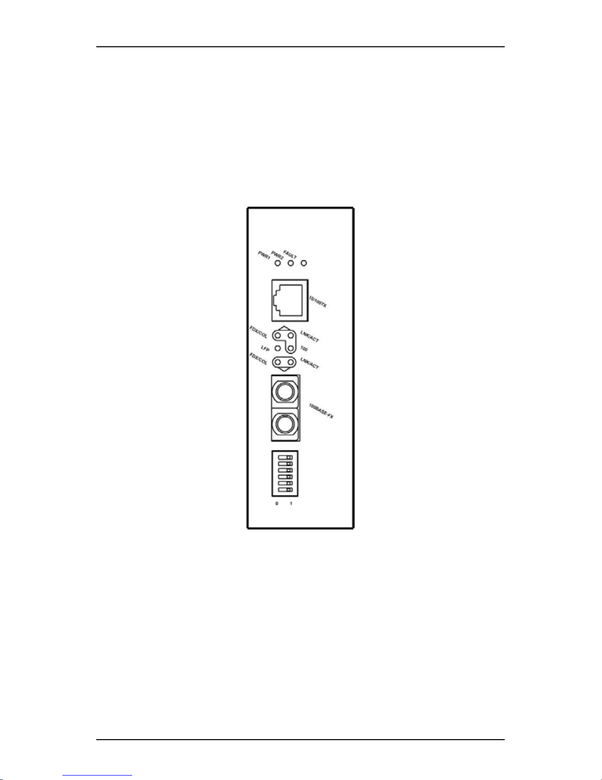
ySupport 802.3/802.3u/802.3x. Auto-negotiation: 10/100Mbps,
full/half-duplex; Auto MDI/MDIX.
y100Base-FX: Multi mode SC or ST type; Single mode SC or ST type;
WDM Single mode SC type.
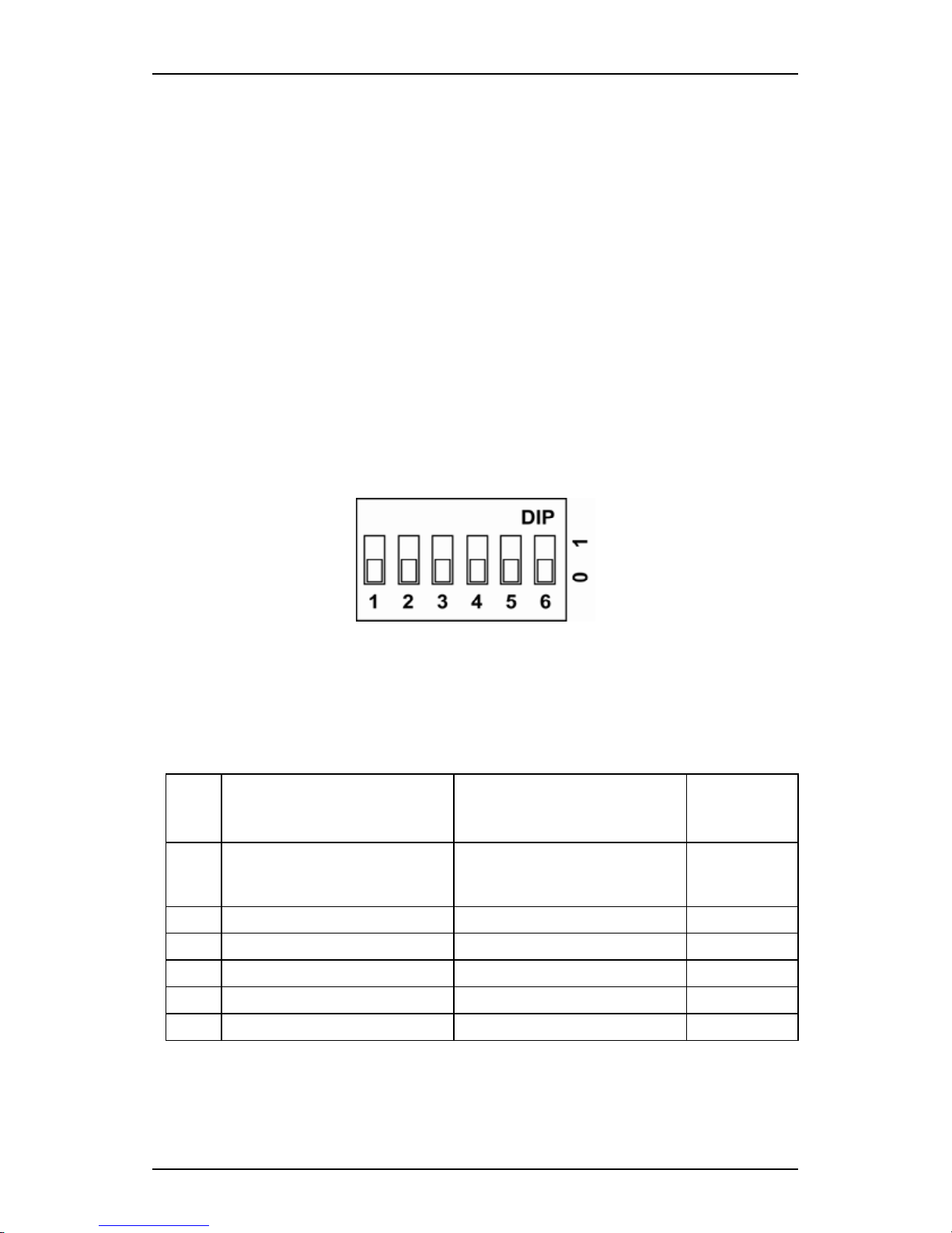
yOne DIP switch for configuring link-fault-pass-through, fixed speed,
full/half duplex, and link down alarm.
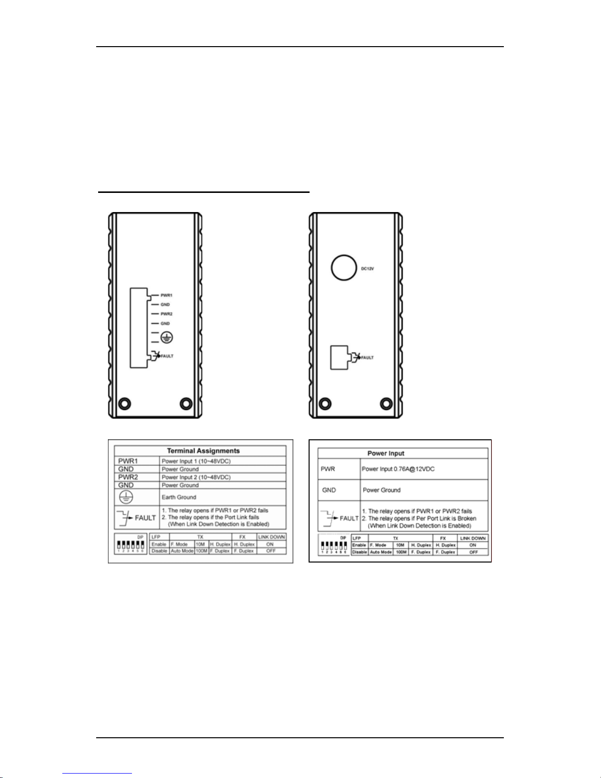
yAlarms for power and port link failure by relay output.
Relay contact rating with current 1.5A @ 24VDC, 0.5A @ 120VAC.
yOperating voltage and Max. current consumption: 0.76A @ 12VDC,
0.38A @ 24VDC, 0.19A @ 48VDC. Power consumption: 9.12W Max.
yPower Supply: Redundant DC Terminal Block power inputs or 12VDC
DC JACK with 100-240VAC external power supply.
yField Wiring Terminal: Use Copper Conductors Only, 60/75℃, 12-24
AWG torque value 7 lb-in.
y-40 to 75 (℃℃-40℉to 167℉) operating temperature range. Tested for
functional operation @ -40 to℃85 (℃-40℉to 185℉). UL1604
Industrial Control Equipment certified Maximum Surrounding Air
Temperature @ 74℃(165℉).
ySupports Din-rail, Panel, or Rack Mounting installation.
yUL1604 Class I, Division 2 Classified for use in hazardous locations
(Applicable to versions with Terminal Block power option).
yThis equipment is suitable for use in Class I, Division 2, Groups A, B, C
and D OR non-hazardous locations only.
yWARNING – EXPLOSION HAZARD – Do not disconnect equipment
unless power has been removed or the area is known to be
non-hazardous.
yWARNING – EXPLOSION HAZARD – Substitution of components
may impair suitability for Class I, Division 2.
Assembly, Startup, and Dismantling
yAssembly: Place the media converter on the DIN rail from above using
the slot. Push the front of the media converter toward the mounting
surface until it audibly snaps into place.
yStartup: Connect the supply voltage to start up the media converter via
the terminal block (or DC JACK).
yDismantling: Pull out the lower edge and then remove the media
converter from the DIN rail.