Lafayette Instrument 89000B User manual

Model 89000B Assembly and Users’ Instructions
1
Electronic Radial Arm Maze
3700 Sagamore Parkway North
P.O. Box 5729 • Lafayette, IN 47903 USA
Tel: 765.423.1505 • 800.428.7545
Fax: 765.423.4111
E-mail: [email protected]
www.lafayetteinstrument.com
Model 89000B
PATHFINDER MAZE SYSTEM
ASSEMBLY INSTRUCTIONS
© 2004 by Lafayette Instrument Company, Inc. All Rights Reserved -Rel. 5.24.04

3700 Sagamore Parkway North . PO Box 5729 . Lafayette, IN 47903 USA . Ph: 765-423-1505
Electronic PathFinder Maze System
2
(A) Installation of the Arena to the Column 3
(B) Installation of Runway Arms to the Column 3
(C) Connection of Lift Arms to the Runways & Doors 4
(D) Attaching the Power Control Box 5
(E) Attaching the Switchbox 5
(F) Installation of the Runway/Bridge Walls 6
(G) Connection to ABET 7
(H) Connection to Photocell Runway Monitor 8
(I) Example ABET Schedule 9
Appendix 1 - Main Assembly Diagram 10
Appendix 2 - Detail of Bridge Diagram 11
Appendix 3 - Runway Wall Assembly Diagram 12
Appendix 4 - Area Configurations Diagram 13
Ordering Information 14
Table of Contents:

Fax: 765-423-4111 . www.lafayetteinstrument.com . E-mail: [email protected]
Model 89000B Assembly and Users’ Instructions
3
Assembly Instructions:
(A) Installation of the Arena to the Column
*See diagram on page 10
Required tools: 5/16” nut driver
1. Place arena on top of the column, assuring that all (8) threaded studs are seated into the
mating slots. Install the (8) kep nuts provided and tighten securely.
2. Check for smooth sliding of the arena doors after installing.
(B) Installation of Runway Arms to the Column
*See diagram on page 10
Required tools: medium size Phillips head screwdriver
1. Mount all eight runway arms to the column. Each arm has keyway slots located on the
back of the arm tabs. Once mounted, tighten all (6) keyway screws securely. (Runway
arms can be installed in any order.)
2. Each arm has a 3.5mm plug that must be connected to the column. Insert each of the
plugs into its proper connector.
arena
runway arms

3700 Sagamore Parkway North . PO Box 5729 . Lafayette, IN 47903 USA . Ph: 765-423-1505
Electronic PathFinder Maze System
4
door connection runway connection
(C) Connection of Lift Arms to the Runways & Doors
*See diagram on page 10
Required tools: none
1. At this point you have the option of attaching the lift arms to the under side of the swivel
portion of the runways or to the slotted door lift bracket connected to the arena. The
provided plastic thumb screws are used for either application. The length of the runways
and the doors are adjusted using the slotted liftarm. When switching from runways to door
or vise-versa, pay careful attention to the height of the raised runway and the depth of the
lowered door. The raised runway should be level with the arena. The lowered door should
close gently, not with a loud noise. If it closes with a loud noise, the lift arm should be
lengthened.
2. Assure these connections operate smoothly and that there is no binding of the
mechanism.
3. Place the eight feeder cups into the open holes located at the end of the runway.
4. At this point rotate the column on the base swivel to assure it moves freely without binding.
When the column is positioned with the numeral one facing the cable mounting panel, this
is considered the mid point or center of rotation. From this point the column can be rotated
170 degrees to the left or 170 degrees to the right of this center point. The column will not
rotate past 170 degrees, as there is a built in rotation stop to prevent the cables from
bending.

Fax: 765-423-4111 . www.lafayetteinstrument.com . E-mail: [email protected]
Model 89000B Assembly and Users’ Instructions
5
(D) Power Control Box
*See diagram on page 10
Required tools: none
1. First, mount the power control box using the two knurl screws at the base of the column.
2. Next, connect the cables to the back of the control box where it its labeled 1 through 8.
3. Connect the IEC cable to the power box, and plug the other side to the 120v outlet.
(E) Switch box
Required tools: None
1. Use the DB-25 cable and attach one side to the switch.
2. Attach the second side of the DB-25 cable to the power box.
3. If you are using a tripod, use the screw mount on the bottom of the switch box.
back of power control box front of power control box

3700 Sagamore Parkway North . PO Box 5729 . Lafayette, IN 47903 USA . Ph: 765-423-1505
Electronic PathFinder Maze System
6
(F) Installation of the Runway/Bridge Walls
(Closed Configuration ONLY) *See diagram on page 11
Required tools: 1/16” hex wrench (included)
5/16” nut driver
1. All polycarbonate walls (F1, F3, and F7) are shipped with a special covering that helped
protect the walls against scratching. The covering must be removed from all walls. This is
easily done by peeling back the corner of the covering and continuing to pull until the
covering is off.
2. Begin by installing 2 bridge walls (F1) on either side of the bridge. The walls are mounted on
the outer side of the bridge wall, with the hex screws inserted through the mounting holes
from the inside of the bridge wall (F5), through the mounting hole (F2), and secured with a
kep nut on the outside of the wall. Be sure that the notch (F4) is in the correct location, at the
intersection of the bridge and runway. At this point, finger tighten the kep nuts. DO NOT
TIGHTEN WITH THE NUT DRIVER!
3. Continue by installing 2 arm walls (F3) on either side of the runway using the same
procedure outlined in step #2 above.
4. Install the end wall (F7) on the end of the runway using the same basic procedure outlined in
step #2 above.
5. Install the corner connectors (F8) and the straight connectors (F9) in the notched areas of the
wall as illustrated in the assembly diagram.
6. Tighten all kep nuts (F6) with the nut driver.
7. Repeat steps #2 - #6 for all remaining arms.

Fax: 765-423-4111 . www.lafayetteinstrument.com . E-mail: [email protected]
Model 89000B Assembly and Users’ Instructions
7
(G) Model 89000B Connections for ABET
Required tools: None
Description:
Using the ABET Starter Interface (Model 81401), or an expander interface (Model 81402),
connections for Model 89000B can be made to ABET using the following guidelines.
1. Connect the ABET Starter interface to the Model 89000B Power box, using the DB-25 M-F
cable. Connect the male end of the cable to the Model 89000B hand controller/ABET input,
and the female end of the cable to the starter or expander interface.
2. Connect the Model 89000B Power box to the Model 81408 I/O block, using a second DB-25
cable. Connect the female end of the cable to the Model 89000B ABET port, and the male
end of the cable to the Model 81408 I/O Block.
3. Connect the Model 81408 I/O block to the starter or expander interface using a third DB-25
cable. Connect the female end of the cable to the Model 81408 I/O block, and the male end of
the cable to the starter or expander interface.

3700 Sagamore Parkway North . PO Box 5729 . Lafayette, IN 47903 USA . Ph: 765-423-1505
Electronic PathFinder Maze System
8
Description:
When using the photocell monitors for the runways of the Model 89000B, all photocell
connections are made through the Model 81408/09 I/O block. For the Model 89000B you can
have a maximum of 16 photocells connected at one time.
1. Locate the first runway, labeled 1. Use the IR mounting kit to mount the photocells on the
outside of the Plexiglas walls. Place the photocells on the IR mounts at the desired positions.
Usually located at the beginning and/or end of the runway.
2. Connect the first photocell to the Model 81408 I/O block.
Red - +28 VDC
Black - GND
Blue - Normally Open connection (Active Low “gnd”)
Clear - Normally Closed connection (Active High “5v”)
3. Connect the Blue wire of the Model 81413 to input #1 of the Model 81408/09 for the first
photocell.
4. Repeat for all remaining photocells, increasing inputs for photocells.
5. Please keep the photocells wiring to the outside of the column.
6. When you apply power to the ABET system with the photocells attached, a red led will light up
on the light source. If the receiver detects the light from the source, the red led on the
receiver will light up. When the red led on the receiver is off, the light source is not detected.
Adjust the photocells to make sure light is detected properly when aligned with the light
source. Make sure the red led turns off properly when the light source beam is broken.
7. All photocells from the Model 81413 are configured as inputs on the ABET system. When the
light source is detected, its’ABET input will read OFF. When the beam is broken, its’ input
changes to ON.
Note: It is important to keep the photocells clean and aligned for proper operation.
Required tools: Flathead Screwdriver (included)
(H) Model 89000B Connections for Photocell Runway Monitor

Fax: 765-423-4111 . www.lafayetteinstrument.com . E-mail: [email protected]
Model 89000B Assembly and Users’ Instructions
9
This schedule allows the animal to explore four arms. It keeps track of the arms explored and
then re-explored. Once each of the four arms are explored the schedule ends.
The default arms are #1, #3, #5, and #7 - essentially a plus configuration. To determine
exploration, “states” are used to keep track of where the animal has been. Each arm has an
associated “state”, using the “ArmFlag” counter, and are defined as:
State “0” - Runway not explored
State “1” - Reached end of runway (Cup Sensor)
State “2” - Exiting runway (Entry Sensor)
State “3” - Another runway is entered (Entry Sensor on other runways)
To map where the animal has been the counter for each arm is incremented as these “states” are
reached. State “3” is unique in that the animal must enter another arm to know it has fully exited
the arm explored. The “ArmFlag” is further incremented from 3 onward to indicate the associated
runway is re-explored. So, if the “ArmFlag” for runway 1 is incremented to 6 then the runway was
re-explored at least two times. Once the “ArmFlag” reaches “3” each Entry Sensor or Cup Sensor
detection causes the “ArmFlag” to increment. The resulting data file can be analyzed to
determine the amount of re-exploration of an arm, essentially the number of times the Entry
Sensor and the Cup Sensor were activated.
Notes:
1. Automatic Door – Turn ON = Door opened or Bridge raised
2. Automatic Door – Turn OFF = Door closed or Bridge lowered
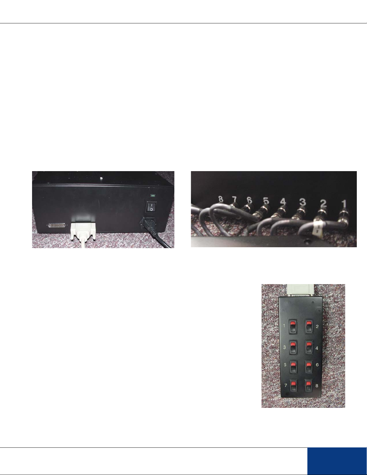
3. Entry Sensors for arms 1 to 8 are physically wired to inputs 1, 3, 5, 7, 9, 11, 13, 15
respectively.
4. Cup Sensors for arms 1 to 8 are physically wired to inputs 2, 4, 6, 8, 10, 12, 14, 16
respectively.
5. All photocell sensors are wired with the Red wire to 28VDC, Black wire to Common, the Blue
wire to the respective input.
(I) Example ABET Schedule

3700 Sagamore Parkway North . PO Box 5729 . Lafayette, IN 47903 USA . Ph: 765-423-1505
Electronic PathFinder Maze System
10
Main Assembly Diagram

Fax: 765-423-4111 . www.lafayetteinstrument.com . E-mail: [email protected]
Model 89000B Assembly and Users’ Instructions
11
Detail of Bridge Diagram

3700 Sagamore Parkway North . PO Box 5729 . Lafayette, IN 47903 USA . Ph: 765-423-1505
Electronic PathFinder Maze System
12
Runway Wall Assembly Diagram

Fax: 765-423-4111 . www.lafayetteinstrument.com . E-mail: [email protected]
Model 89000B Assembly and Users’ Instructions
13

3700 Sagamore Parkway North . PO Box 5729 . Lafayette, IN 47903 USA . Ph: 765-423-1505
Electronic PathFinder Maze System
14
3700 Sagamore Parkway North
P.O. Box 5729 • Lafayette, IN 47903 USA
Tel: 765.423.1505 • 800.428.7545
Fax: 765.423.4111
E-mail: [email protected]
www.lafayetteinstrument.com
Ordering Information:
All phone orders must be accompanied by a hard copy of
your order. All must include the following information:
1) Complete billing and shipping addresses
2) Name and department of end user
3) Model number and description of desired item(s)
4) Quantity of each item desired
5) Purchase order number or method of payment
6) Telephone number
DOMESTIC TERMS
There is a $50 minimum order. Open accounts can be
extended to most recognized educational institutions,
hospitals and government agencies. Net amount due 30
days from the date of shipment. Enclose payment with the
order;chargewithVISA,MasterCard;orpayCOD.Wemust
have a hard copy of your order by mail or fax. Students,
individuals and private companies may call for a credit
application.
INTERNATIONAL PAYMENT INFORMATION
There is a $50 minimum order. Payment must be made in
advance by: draft drawn on a major US bank; wire transfer
to our account; charge with VISA, MasterCard; or
confirmed irrevocable letter of credit. Proforma invoices
will be provided upon request.
RETURNS
Equipment may not be returned without first receiving
a Return Goods Authorization Number (RGA).
Whenreturningequipmentfor service, please call Lafayette
Instrument to receive a RGA number. Your RGA number
willbegoodfor 30 days. Address theshipmentto:Lafayette
Instrument Company, 3700 Sagamore Parkway North,
Lafayette,IN 47904, U.S.A. Shipments cannotbe received
at the PO Box. The items should be packed well, insured
for full value, and returned along with a cover letter
explaining the malfunction. Please also state the name of
theLafayetteInstrumentrepresentativeauthorizingthereturn.
An estimate of repair will be given prior to completion ONLY
if requested in your enclosed cover letter. We must have a
hard copy of your purchase order by mail or fax, or repair
work cannot commence.
WARRANTY
Lafayette Instrument guarantees its equipment against all
defects in materials and workmanship to the ORIGINAL
PURCHASER for a period of one (1) year from the date of
shipment, unless otherwise stated. During this period,
Lafayette Instrument will repair or replace, at its option, any
equipmentfound to be defective inmaterials or workmanship.
If a problem arises, please contact our office for prior
authorization before returning the item. This warranty does
not extend to damaged equipment resulting from alteration,
misuse, negligence or abuse, normal wear or accident. In no
event shall Lafayette Instrument be liable for incidental or
consequential damages. There are no implied warranties or
merchantability of fitness for a particular use, or of any other
nature. Warranty period for repairs or used equipment
purchased from Lafayette Instrument is 90 days.
DAMAGED GOODS
Damaged equipment should not be returned to Lafayette
Instrument prior to thorough inspection.
When a shipment arrives damaged, note damage on delivery
bill and have the driver sign it to acknowledge the damage.
Contact the delivery service, and they will file an insurance
claim. When damage is not detected at the time of delivery,
contact the carrier and request an inspection within 10 days
of the original delivery. Please call the Lafayette Instrument
Customer Service Department for a return authorization for
repair or replacement of the damaged merchandise.
Lafayette Instrument Co. Europe
4 Park Road, Sileby,
Loughborough, Leics., LE12 7TJ. UK.
Tel: +44 (0)1509 817700
Fax: +44 (0)1509 817701
E-mail: [email protected]
The material presented in this publication is copyright-protected and may not be reproduced in any form, by any method, for any purpose
without the prior written consent of Lafayette Instrument Company. © 2004 by Lafayette Instrument Company, Inc.
Table of contents