SAFETY & OPERATIONAL PRECAUTIONS
For proper performance do NOT modify, substitute nozzle, hose diameter or length.
Manufacturer assumes no liability for the use or misuse of this unit.
Wear protective clothing, gloves and eye-wear when working with chemicals.
Always direct the discharge away from people and electrical devices.
For pressures over 100 PSI, remove the discharge valve or lower pressure
Follow the chemical manufacturer’s safe handling instructions.
Turn off solution supply and air when unit is not in use for extended periods.
TO INSTALL (REFER TO DIAGRAM ON NEXT PAGE)
A check valve is required on the foamer solution inlet to prevent air from going back into the solution line. (See
Options)
1. Mount the unit to a suitable surface.
2. Connect the discharge hoses as shown in the diagram and close the ball valves.
3. Install a solution check valve on the foamer solution inlet(s) and connect pre-mixed solution supply.
4. To prevent blocking the small jets, flush any new plumbing of debris before connecting. (And/or install a strainer)
5. Connect compressed air supply. If piping is older and has known contaminants, install a filter.
TO OPERATE
Always make sure the discharge is closed or pointed in a safe direction before turning inlet valve on. Discharge
can be shut off at any time during operation but should not be left off for long periods of time with the inlet
valve on.
TO FOAM
1. With wand in hand open the inlet ball valve, and the air ball valve.
Wait a few seconds and observe foam consistency.
Use the least amount of air needed to achieve good foam quality to prevent solution pressure
fluctuations from affecting performance. Air pressure must be kept lower than solution pressure.
To adjust the foam consistency pull out on the air regulator knob, turn slightly clockwise for dryer foam
and counterclockwise for wetter foam. Wait a few seconds to see each adjustment.
Medium wet foam will give the best cleaning results! Dry foam will NOT clean as well!
You may also have to try different chemical ratios and air settings until foam consistency and cleaning
results are acceptable. Once this is set and desired foam consistency is achieved push lock the knob.
you are ready to start application.
2. When foaming is completed, close the discharge ball valve, return to the unit and close the solution and air ball
valves. Briefly re-open the discharge ball valve to relieve pressure in the hose. Rinse before the foam dries.
TO RINSE
1. With spray wand in hand and the discharge ball valve closed open the inlet ball valve.
2. Open the discharge ball valve to rinse.
3. When complete, close the discharge ball valve then close the inlet ball valve.
4. Briefly re-open the discharge ball valve to relieve pressure in hose.
UNIT FLOW RATES
PSI GPM
FOAM RINSE
35 1.59 6.73
40 1.70 7.20
50 1.90 8.05
60 2.08 8.82
70 2.25 9.52
80 2.40 10.18
90 2.55 10.80
100 2.69 11.38
110 2.82 11.94
120 2.94 12.47
125 3.01 12.73
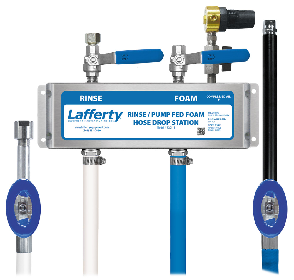
920118 • Rinse / Pump Fed Foam Hose Drop Station
- Page 2 -


