Laing BM mini Series User manual
Installation and operation manual
for mixing set BM mini

2
Installation and operation manual BM mini
www.laing.de
www.laing.de
www.laing.de
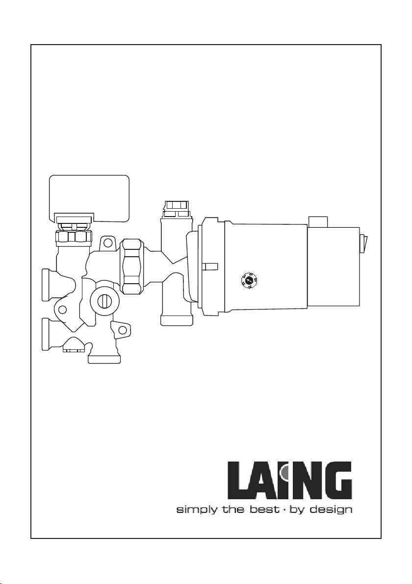
Design BM mini
1. Version KF = Remote sensor thermostat (8-26°C, 5 m) or
Version RT = thermoelectric drive for the connection of a room
thermostat (not included in delivery) or
Version KR = thermoelectric drive, pre-wired with pump including
a constant temperature control (A1-121 R, 20-70°C) for the
connection of a room thermostat (not included in delivery)
2. Laing circulating pump with spherical motor A1-121 resp. A1-121 R
3. Venting device
4. Supply radiator-/boiler circuit
5. Return radiator-/boiler circuit
6. Supplyoorheatingcircuit
7. Returnoorheatingcircuit
8. Adjustable mixing valve
9. Adjustable bypass for the radiator-/boiler circuit
(recommended to be closed)
10. ON-OFF-switch for pump
11. Flow temperature setting (KR version only)
10
2
6
7
9
5
4
8
1
3
11

www.laing.de
3
www.laing.de
Installation and operation manual BM mini
Table of contents
Design BM mini ...........................................................................................2
Technical Data..............................................................................................3
Application....................................................................................................4
Mounting instructions....................................................................................4
Hydraulic connection ....................................................................................5
Filling and priming the UFH system..............................................................6
Starting of operation without given values..................................................12
Starting of operation with given values (pre-setting) .................................. 13
Assembly of wall bracket............................................................................15
Dimensional drawing ..................................................................................16
Pump curve ................................................................................................16
Product range, accessories and spare parts..............................................17
Electrical connection...................................................................................18
Technical Data
Max. system pressure 1 Mpa (10 bar)
Max.systemtemperature 110°C(boilercircuit),55°C(oorheating)
Max. differential pressure 100 kPa (1 bar) in the
radiator-/boiler circuit
Electrical connection 1 x 230 V / 50 Hz
Power consumption 25 Watt (circulating pump)

4
Installation and operation manual BM mini
www.laing.de
www.laing.de
www.laing.de
Application
• TheBMminiisdesignedtosupplyoorheatingareasuptoapprox.40
sqm (from pipe 16x2 mm onwards) in one- or two-pipe-systems. The
connectionofupto2oorheatingcircuitsispossible.
• Three versions are available:
BM mini KF: Mixing set with room temperature guided control,
made of thermostat (10-26°C + frost protection)
with remote sensor (5 m).
BM mini RT: Mixing set for temperature guided control, made
of thermoelectric drive for the connection of a room
thermostat (room thermostat not included in
delivery- see accessories in product range).
BM mini KR: Mixing set with integrated constant temperature
control (20-70°C) for the connection of a room
thermostat (room thermostat not included in
delivery- see accessories in product range).
• The BM mini is provided with a temperature protection system that
restrictsthesupplytemperatureintheoorheatingcircuittomax.55°C.
Mounting instructions
• BM mini will be connected directly to the existing radiator-/boiler circuit.
• When two circuits are connected to the BM mini, the shortest circuit
must be balanced by using an adjustable return screw connection.
• The BM mini has to be mounted in a horizontal position (see page 2).
Left or right connection to the radiator-/boiler circuit is possible (see
page 9).
• TheBMminihastobeinstalledonahigherlevelthantheoorheating
installation.

www.laing.de
5
www.laing.de
Installation and operation manual BM mini
• Ensure that the pre-pressure to the BM mini from the radiator-/vessel
circuit is minimum 10 kPa (1 m).
• BeforerunningtheBMminipleasecheck,thattheoorheatingsystem
islled,completelyvented,andprovedagainstleakage.
• Since the circulation pump might create under certain circumstances
someownoise,theBMminishouldbeplacedawayfromnoise
sensitive areas (i.e. sleeping rooms).
• The water temperature in the supply radiator-/boiler circuit should be at
least10Khigherthanintheoorheatingsupply.
• The maximum length of each pipe must not be longer than 100 m for
oorheatingdesignwithspreadof10Kwhenusingpipes12mmi.d.
(i.e. pipe 16x2). Smaller diameter pipe results in a shorter pipe length.
• BM mini KF: Assemble the thermostatic head and mount the
sensor in an appropriate position in the room and
about1,7mabovetheoor.Useavacantpipeif
possible.
• BM mini RT: Wiring of the electrical actuator and the room
thermostat
BM mini KR: onlybyaqualiedelectrician.
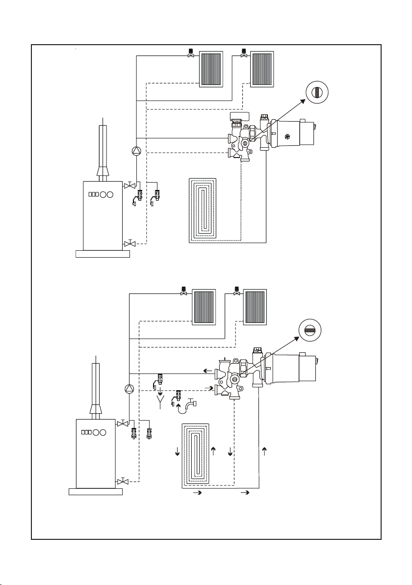
Hydraulic connection of two-pipe systems
Bypass valve closed.
Allen key 2,5mm.

6
Installation and operation manual BM mini
www.laing.de
www.laing.de
www.laing.de
Filling of the system
Itismandatorytoushtheoorheatingloopsbeforeputtingthesystem
in operation, because otherwise malfunction or damage to the pump may
result.WerecommendusingtwollvalvesontheprimarysideoftheBM
miniasshowninpicture2.Alternatively,thesystemcanbelledusingll
valves installed elsewhere in the system. In any case, it is necessary to
positivelyushthesystemsinceotherwisetheairinthesystemwillnotbe
purged completely. Filling the system via the integrated manual air vent
(see picture 7) is not possible! Please observe the position of the ball valve
inthebypass.Ifthisisintheverticalposition,theoorheatingloopsare
hydraulically uncoupled from the boiler loop. This position is ideal for nor-
mal operation (see picture 1) since the pump in the heating loop does not
inuencetheoorheatingloop.Withthevalveinthisposition,however,the
oorheatingsystemcannotbelledfromtheprimaryside.
Tolltheoorheatingloopsfromtheheatingloopside,thisballvalvemust
beclosed(horizontal)–seepictures2through6.Afterlling,thevalve
mustbeopenedagain(verticalposition).Pleaseobservethatwhenlling
from the primary side radiator valves on that side should be closed in order
tohavemaximumpumppressureavailableforpurgingtheoorheating
loops.
www.laing.de
7
www.laing.de
Installation and operation manual BM mini
! ! !
Normal operation. Ball valve position open (vertical)
!!!
Recommendedllingofthesystem.Twollvalvesontheprimarysideofthe
BMminiallowforaneasyllingandpurgingofairintheoorheatingloops.
The ball valve position must be closed (horizontal).
Picture 1
Picture 2

8
Installation and operation manual BM mini
www.laing.de
www.laing.de
www.laing.de
! ! !
Goodllingoption.Twoexistingllvalvesontheprimarysideallowforgood
llingandairpurging.Theballvalvepositionmustbeclosed(horizontal).
! ! !
Possiblellingoption,albeitalittlecomplicated.Onellvalveontheprimary
owsideallowsforllingandairpurging.Theintegratedballvalvemustbe
closed (horizontal). Caution:TheoorheatingreturnattheBMminimustbe
closedduringthelloperation.Fillingawallheatingloopisimpossibleinthis
way.
Picture 3
Picture 4

www.laing.de
9
www.laing.de
Installation and operation manual BM mini
!!!
Possiblellingoption,albeitalittlecomplicated.Onellvalveontheprimary
returnsideallowsforllingandairpurging.Theintegratedballvalvemustbe
closed (horizontal). Caution:TheoorheatingowattheBMminimustbe
closedduringthelloperation.Fillingawallheatingloopisimpossibleinthis
way.
Picture 5

10
Installation and operation manual BM mini
www.laing.de
www.laing.de
www.laing.de
!!!
Thedirectionofowshownisonlypossibleifthereisnocheckvalve
installed at the primary heating circulator. If a check valve is present,
llinginaccordancewithpicture3isrecommended.
Picture 6
This manual suits for next models
3
Table of contents
Popular Control Unit manuals by other brands

Festo
Festo Compact Performance CP-FB6-E Brief description

Elo TouchSystems
Elo TouchSystems DMS-SA19P-EXTME Quick installation guide

JS Automation
JS Automation MPC3034A user manual

JAUDT
JAUDT SW GII 6406 Series Translation of the original operating instructions

Spektrum
Spektrum Air Module System manual

BOC Edwards
BOC Edwards Q Series instruction manual

KHADAS
KHADAS BT Magic quick start

Etherma
Etherma eNEXHO-IL Assembly and operating instructions

PMFoundations
PMFoundations Attenuverter Assembly guide

GEA
GEA VARIVENT Operating instruction

Walther Systemtechnik
Walther Systemtechnik VMS-05 Assembly instructions

Altronix
Altronix LINQ8PD Installation and programming manual


