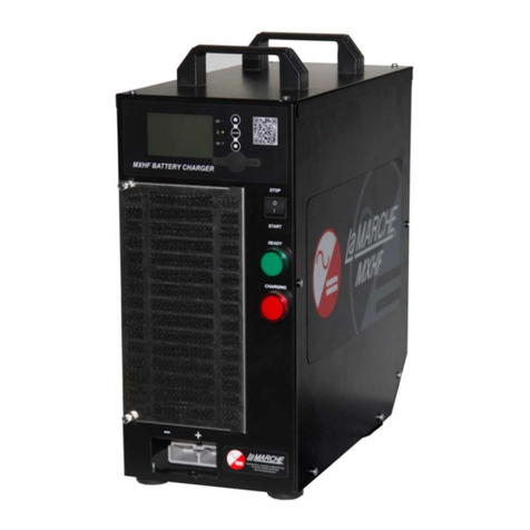
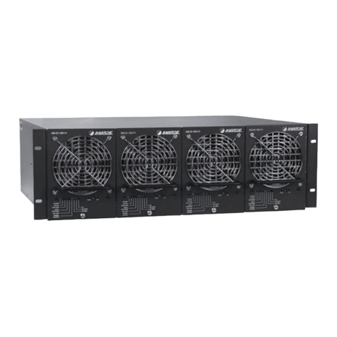
Lamarche MXHF User manual

106 Bradrock Dr. Des Plaines, IL 60018-19671 CPN 128964 Instr ction Drawing N mber: P25-LMXHF
Tel: 847 299 1188 Fax: 847 299 3061 Revision A00 Rev. Date: 03/14 ECN: 20355
La Marche Man fact ring Company
www.lamarchemfg.com
MXHF
MXHFMXHF
MXHF
Motive Power Battery Charger
Installation and Operation Man al

2
Important Safety Instructions
Before sing this eq ipment read all man als and other doc ments related to this nit and other eq ipment
connected to this nit. Always have a copy of a nits man al on file nearby, in a safe place; if a replacement
copy of a man al is needed it can be fo nd at the www.lamarchemfg.com.
Electrical Safety
WARNING:
Hazardo s Voltages are present at the inp t of power systems. The o tp t from
rectifiers and from batteries may be low in voltage, b t can have a very high c rrent capacity that
may ca se severe or even fatal inj ry.
When working with any live battery or power system, follow these preca tions:
•Never work alone on any live power system, someone sho ld always be close eno gh to come to yo r aid
•Remove personal metal items s ch as rings, bracelets, necklaces, and watches.
•Wear complete eye protection (with side shields) and clothing protection.
•Always wear gloves and se ins lated hand tools.
WARNING:
Lethal Voltages are present within the power system. Parts inside the nit may still be
energized even when the nit has been disconnected from the AC inp t power. Check with a meter
before proceeding. Do not to ch any nins lated parts.
•A licensed electrician sho ld be sed in the installation of any nit.
•Always disconnect the nit from the s pply, batteries and loads before performing maintenance or cleaning.
•If the nit is hot-swappable, simply remove it from the shelf for any maintenance or cleaning.
•Always ass me that an electrical connection is live and check the connection relative to gro nd.
•Be s re that neither liq ids nor any wet material come in contact with any internal components.
•Do not operate this nit o tside the inp t and o tp t ratings listed on the nit nameplate.
•Do not se this nit for any p rpose not described in the operation man al.
Mechanical Safety
•This nit or parts of the nit may get very hot d ring normal operation, se care when working nearby.
•Do not expose eq ipment to rain or snow. Always install in a clean, dry location.
•Do not operate eq ipment if it has received a sharp blow, been dropped, or otherwise damaged in any way.
•Do not disassemble this nit. Incorrect re-assembly may res lt in a risk of electric shock or fire.
Battery Safety
WARNING:
Follow all of the battery man fact rer’s safety recommendations when working with or
aro nd battery systems. DO NOT smoke or introd ce a spark or open flame in the vicinity of a
battery. Some batteries generate explosive gases d ring normal battery operation.
•To red ce risk of arc, connect and disconnect the battery only when the nit is off.
•If it is necessary to remove the battery connections, always remove the gro nded terminal from the battery
first.
•Remove personal metal items s ch as rings, bracelets, necklaces, and watches.
•Always wear r bber gloves, safety glasses, and a r bber lined vest/apron when working near a battery.
•Have plenty of fresh water and soap nearby in case the battery electrolyte contacts skin, clothing, or eyes.
•If the battery electrolyte contacts skin or clothing, wash immediately with soap and water.
•If the electrolyte enters the eye, immediately flood the eye with r nning cold water for at least ten (10)
min tes and seek medical attention immediately.
•Do not drop metal on a battery. A spark or short-circ it co ld occ r and co ld ca se an explosion.

3
Unit Location
•Allow at least 6 inches of free air on all vented s rfaces for proper cooling
•Allow s fficient clearance to open the front panel for servicing.
•Do not operate this nit in a closed-in area or restrict ventilation in any way.
•Do not set any battery on top of this nit.
•Never allow battery electrolyte to drip on this nit when reading the specific gravity or filling the battery.
•Never place this nit directly above a standard flooded battery. Gases from the battery will corrode and
damage eq ipment.
•A sealed maintenance free or valve reg lated lead acid (VRLA) battery may be placed below this eq ipment.
Chec for Damages
Prior to npacking the prod ct, note any damage to the shipping container. Unpack the prod ct and inspect the
exterior of prod ct for damage. If any damage is observed, contact the carrier immediately. Contin e the
inspection for any internal damage. In the nlikely event of internal damage, please inform the carrier and
contact La Marche for advice on the risk d e to any damage before installing the prod ct. Verify that yo have
all the necessary parts per yo r order for proper assembly.
CAUTION:
Fail re to properly file a claim for shipping damages, or provide a copy of the claim to La
Marche, may void warranty service for any physical damages reported for repair.
Returns for Service
Save the original shipping container. If the prod ct needs to be ret rned for service, it sho ld be packaged in its
original shipping container. If the original container is damaged/ navailable, make s re the prod ct is packed
with at least three inches of shock-absorbing material to prevent shipping damage.
La Marche is not
responsible for damage ca sed by improper packaging of ret rned prod cts.
Inspection Chec list
Enclos re exterior and interior is not marred or dented.
There is no visible damage components.
All internal components are sec re.
Printed circ it boards are firmly seated.
All hardware and connections are tight.
All wire terminations are sec re.
All items on packing list have been incl ded.
Handling
Eq ipment can be very heavy and/or top heavy. Use adeq ate manpower or eq ipment for handling. Until the
eq ipment is sec rely mo nted, care m st be sed to prevent the eq ipment from being accidentally tipped
over.

4
Table of Contents
Important Safety Instr ctions .................................................................................................................. 2
Electrical Safety .................................................................................................................................. 2
Mechanical Safety ............................................................................................................................... 2
Battery Safety..................................................................................................................................... 2
Unit Location ...................................................................................................................................... 3
Check for Damages ............................................................................................................................. 3
Ret rns for Service.............................................................................................................................. 3
Inspection Checklist.......................................................................................................................... 3
Handling ............................................................................................................................................ 3
Table of Contents ................................................................................................................................... 4
Model Scope/General Description ............................................................................................................. 6
Understanding the Model N mber ............................................................................................................ 6
1
Eq ipment Handling ......................................................................................................................... 7
1.1
Storing the MXHF ..................................................................................................................... 7
1.2
Placement of the MXHF............................................................................................................. 7
2
Installing the MXHF.......................................................................................................................... 8
2.1
Mo nting the MXHF .................................................................................................................. 8
2.2
Making the AC Inp t Connections............................................................................................... 9
2.2.1
B s Bar Selection.................................................................................................................. 9
2.2.2
A xiliary Power S pply Voltage Selection ................................................................................10
2.2.3
AC Inp t Connections...........................................................................................................10
2.3
Relay Config ration .................................................................................................................11
2.4
Alarms ...................................................................................................................................11
2.4.1
Charger Related Alarms ........................................................................................................12
2.4.2
Battery Related Alarms .........................................................................................................13
3
Operation of the MXHF ....................................................................................................................14
3.1
Front View of the MXHF ...........................................................................................................14
3.2
Charger Mod les .....................................................................................................................15
3.3
Optional A to Profile Config ration (APC) Mod le........................................................................15
3.4
Normal Operation....................................................................................................................15
3.4.1
Pre-Charge Checks...............................................................................................................15
3.4.2
Stop/Start Rocker Switch ......................................................................................................16
3.4.3
Charge Complete .................................................................................................................16
3.4.4
Fa lt indicators....................................................................................................................16
3.4.5
Eq alize Next Cycle..............................................................................................................16
3.4.6
Battery Disconnection...........................................................................................................16
3.5
LCD Display ............................................................................................................................17
3.5.1
LCD View in the Resting State ...............................................................................................17

5
3.5.2
LCD View in the Charging State .............................................................................................17
3.5.3
LCD View in the Charge Complete State .................................................................................18
3.6
MXHF Stat s Indication ............................................................................................................18
3.7
MPC35 Controller Mod le .........................................................................................................19
3.8
Charger Interface Software ......................................................................................................19
3.8.1
System Req irements...........................................................................................................19
3.8.2
Installation..........................................................................................................................19
3.8.3
Operator Access Level Control ...............................................................................................19
3.8.4
Charger Interface Tabs.........................................................................................................19
3.8.5
Charge Profile Factory Settings ..............................................................................................20
3.8.6
Alarm Factory Settings..........................................................................................................22
4
Service...........................................................................................................................................23
4.1
Maintenance ...........................................................................................................................23
4.2
Tro bleshooting ......................................................................................................................24
Appendix A: Man fact rer’s Warranty ......................................................................................................26
Appendix B: MXHF Specifications.............................................................................................................27
Appendix C: AC C rrent Draw .................................................................................................................28
Appendix D: Glossary.............................................................................................................................29
Appendix E: Doc ment Control and Revision History..................................................................................31

6
Model Scope/General Description
The La Marche model MXHF is a high freq ency battery charger designed for se in ind strial applications. The
MXHF is offered with DC o tp t voltages of 24, 36 and 48VDC with o tp t c rrents of 60, 120 and 180ADC.
These chargers may be powered with 208-240VAC single phase or three phase. For 380-480VAC three phase
only.
Understanding the Model Number
The MHHF model n mber is coded to describe the options that are incl ded. Find the model n mber on the
nomenclat re nameplate of the charger. Then follow the example below to determine the config ration of yo r
battery charger.

7
1 Equipment Handling
1.1 Storing the MXHF
If the MXHF is to be stored for more than a few days after delivery, it sho ld be stored within its shipping
container. The location chosen for storage sho ld be within an ambient temperat re of -20°C to +70°C with
a non-condensing relative h midity of 5 to 95%.
1.2 Placement of the MXHF
The preferred installation is where the charger(s) can be located on a table or shelf, protected against
accidental contact with the lift tr ck or its forks. The MXHF has r bber feet on its base for simple placement on
a table or shelf.
With the MXHF on a shelf the risk of
damage to the charger or battery cables
is greatly red ced.
Avoid j st placing the MXHF on the
floor next to the lift tr ck.
Figure
1
–
Plac
ement of the MXHF

8
2 Installing the MXHF
2.1 Mounting the MXHF
There is an optional niversal mo nting bracket that can be fixed to the base, side and rear panels of the MXHF
charger. The bracket enables the charger to be screwed or bolted to the bench, wall or floor s rface and helps
to protect the charger against physical damage.
Mo nting Bracket
–
Base Mo nt
1. Fix the Mo nting Bracket
to a bench sing a type
of fastener that s its the
bench material.
2. Slot the base of the
MXHF onto the mo nting
bracket.
3. When fitting the battery
cable ens re the locking
screw is installed.
Mo nting Bracket
–
Side Mo nt
1. Fix the Mo nting Bracket
to the wall sing a type
of fastener that s its the
wall material.
2. Slot the side of the MXHF
onto the mo nting
bracket.
3. When fitting the battery
cable ens re the locking
screw is installed.
Mo nting Bracket
–
Rear Mo nt
1. Fix the Mo nting Bracket
to the wall sing a type
of fastener that s its the
wall material.
2. Slot the rear of the MXHF
onto the mo nting
bracket.
3. When fitting the battery
cable ens re the locking
screw is installed.
Figure
2
–
Mounting the MXHF

9
2.2 Ma ing the AC Input Connections
AC inp t config ration is done at the factory prior to delivery once a c stomer’s AC main has been verified. The
available inp ts are listed in the table below.
The process has been simplified sing the AC filter board which is mo nted inside of the MXHF. Simply remove
the top cover to access the AC filter board, it incl des mo nting posts for b s bar selection and headers for
a xiliary power s pply voltage selection. Follow three easy steps to verify or config re proper AC inp t for the
MXHF.
2.2.1 Bus Bar Selection
Config ring the B s Bars on the AC filter board negates the need to rewire the AC inp ts to the charger
mod les. Use an 8mm socket on the M5 hex head bolts to sec re the B s Bars in place. Un sed B s Bar
connectors are bolted to the internal rear of the MXHF cabinet.
AC Input Voltage Bus Bar Selection
208-240 Single Phase J14-J15-J16
J17-J18-J19-J20
208-240 Three Phase
J14-J18
J15-J19
J16-J20
480V Three Phase J17-J18-J19-J20
Figure
3
–
AC Filter Board
Mo nting posts for B s
Bar Selection (Step 1)
Headers for a xiliary power
s pply voltage selection (Step 2)

10
2.2.2 Auxiliary Power Supply Voltage Selection
The a xiliary pl g provides AC for the A xiliary DC Power S pply that powers the MPC35 control PCB and its
associated display and indicators. Connect the pl g to the appropriate header, refer to the table below.
AC Input Voltage Aux. Power Voltage
Selection Plug
208-240V J5
480V J6
2.2.3 AC Input Connections
The AC inp t cables are terminated onto the AC filter board via a five way terminal strip marked A, B, C for
phases 1, 2 and 3, D for ne tral and E for earth. Fo r config rations are available and are listed below.
L1 A
N D
L1 D
L2 C
N E
L1 A
L2 B
L3 C
L1 A
L2 B
L3 C
Configuration 1: 208-240VAC
Single Phase
Configuration 2: 208-240VAC
Single Phase Split Leg
Configuration 3: 208-240VAC
Three Phase
Configuration 4: 480VAC
Three Phase
Figure
4
–
AC Input Terminal Bloc

11
2.3 Relay Configuration
All relay contacts are located on the MPC35 Controller mod le. To access relay connections, simply remove the
right side cover of the MXHF. Always be ca tio s when opening p the MXHF, make s re the power is not
coming into the nit.
Relay Function Contacts State
(Factory setting)
Contacts State
when condition
occurs
Connections
S-C
Jumper Conf.
(Factory
setting)
1 Charge Complete Normally Closed Open RY1 J104 (Pin 2-3)
2 A to Watering Active Normally Closed Open RY2 J108 (Pin 2-3)
3 Charge Active Normally Closed Open RY3 J113 (Pin 2-3)
4 Alarm 1* Normally Open Closed RY4 J115 (Pin 2-3)
5 Alarm 2* Normally Open Closed RY5 J106 (Pin 2-3)
6 Not sed - - RY6 J117 (Pin 2-3)
The relays can be config red for normally closed or normally open contacts by setting p the j mpers J104,
J108, J113, J115, and J106. Relay 6 is not sed. Refer to the table below.
Relay Normally Closed Normally Open
1 J104 (Pin 2-3) J104 (Pin 1-2)
2 J108 (Pin 2-3) J108 (Pin 1-2)
3 J113 (Pin 2-3) J113 (Pin 1-2)
4 J115 (Pin 1-2) J115 (Pin 2-3)
5 J106 (Pin 1-2) J106 (Pin 2-3)
* Refer to section (3.8.6 Alarm Factory Settings) for more details
Figure
5
–
MPC35 Controller Mod
ule
Relays
Jumpers
Relay
Contacts

12
2.4 Alarms
The MXHF incl des comprehensive protection and alarm monitoring. The alarms are graded into Urgent and
Non- rgent alarms. Urgent alarms indicate a dangero s condition that immediately stops the charge cycle.
Non-urgent alarms are indicated on the LCD and are logged in the alarm log b t do not act ally stop the
charge cycle.
2.4.1 Charger Related Alarms
Main Switch <Urgent> shows the stat s of the front panel start/stop toggle switch.
Inlet Filter <Non- rgent> can give a warning as to when the inlet filter needs servicing b t is not enabled by
defa lt.
Low Mains <Non- rgent> gives an indication of variation in the inp t mains voltage witho t act ally affecting
the ability of the charger to provide rated o tp t. It might also indicate that a Charger Mod le is being
overloaded.
Mains Fail <Urgent> a mains loss sit ation and the charge cannot proceed.
Non-Urgent Rectifier Fail <Non- rgent> there is a power mod le that is not providing o tp t, the Charger is
still operating b t red ndancy has been lost. Red ced power o tp t and longer charge time as a res lt.
Urgent Rectifier Fail <Urgent> if the n mber of power mod les not providing o tp t eq als or exceeds the
setting for rgent mod le co nt in the PC application monitor tab then the charger will stop. If the rgent
mod le co nt is set to one then the Charger is config red witho t red ndancy and a single fa lt will stop the
charge.
Rectifier Over Temperature <Urgent> normally related to a blocked filter, restricted exha st air or
installation in an inappropriate location.
Configuration Error <Urgent> the Charger cannot meet the target c rrent req ired by the controller even
with all fitted power mod les operating. The config ration does not meet the limits set for a 10A or 15A mains
inp t hardware limited charger.
Output Fuse <Urgent> a blown f se in nearly all cases is ca sed by connecting a reverse polarity battery to
the Charger. When a f se is blown check all cells for a reversed cable connection, a common problem with first
charge of shift batteries that have not been previo sly tested in a lift tr ck. After replacing a battery or Charger
cable always check the polarity before pl gging the battery into the Charger.
No Output Current <Urgent> the charger is not providing the expected o tp t c rrent. Generally related to a
premat re disconnection of the battery, b t also co ld be an incorrectly inserted power mod le.
Monitor ADC Fail <Urgent> the internal watchdog of the MPC35s micro-controller is indicating a major fa lt
and potential npredictable behavior if the Charger is left r nning.

13
2.4.2 Battery Related Alarms
Over discharged Battery <Urgent> the battery is still nder 1.9 V/C after 30 seconds of charge and indicates
a fa lty battery that needs investigation.
Deeply Discharge Battery <Non- rgent> the battery initially is nder 1.9 V/C b t recovers within 30 seconds
of the charge cycle start, this alarm normally comes p when a battery is npl gged from the lift tr ck and
immediately pl gged into the Charger.
Sulphated Battery <Urgent> the battery fails to complete a de-s lphation profile applied by the Charger
correctly and generally means that the battery req ires attention.
Incorrect Battery <Urgent> the battery is inappropriate for the config ration of the charger and cannot be
charged witho t reconfig ring the charger to s it the battery.
Bul Charge Timeout <Urgent> the battery has exceeded the maxim m time allowed for the initial constant
c rrent b lk charge phase. Co ld indicate a fa lty battery or the charger config ration is not correct for the size
of battery to be charged. May need additional Charger Mod les added to the Charger.
Finishing Charge Timeout <Non- rgent> the battery has exceeded the maxim m time allowed for the
finishing part of the charge cycle. Generally not a problem and indicates the battery did not q ite perform as
expected. Not ncommon with new batteries that are still cycling p to f ll capacity (allow 10 cycles) however if
the alarm is a reg lar occ rrence it needs investigation and possible adj stment of the charger or service of the
battery.
Battery Disconnected <Urgent> the battery has been npl gged before charge cycle has complete. This can
damage the battery connector and increase risks of battery explosions as sparks aro nd batteries at their top of
charge whilst gassing can be very dangero s. If the battery needs to be disconnected mid cycle, the toggle
switch m st be first set to STOP. This will stop the charge and log a partial cycle in the charge log b t allows
safe disconnection of the battery.
Reversed Battery <Urgent> a battery with it’s pl s and min s cables reversed has been connected to the
charger. Generally this will also ca se an o tp t f se alarm and the need to replace the chargers DC o tp t
f se(s). S ch a sit ation is not covered by warranty as new batteries sho ld always first be checked for correct
polarity BEFORE pl gging onto the lift tr ck or a charger.
Minimum dV/dt <Non-Urgent> details the change in battery voltage over time. The alarm occ rs when the
change in voltage exceeds the val e set in the profile settings. This alarm also indicates the termination of a
s ccessf l charge.
Maximum Cell Voltage <Non-Urgent> occ rs when the voltage per cell exceeds the val e set in the profile
settings. Typically 2.7 V/C for lead acid batteries.
Batt Over Temp – Start <Urgent> occ rs when the battery temperat re meas red before a charge profile
starts exceeds the val e set in the controller settings. This alarm will not allow the charge profile to contin e.
Batt Over Temp – Charge <Non-Urgent> occ rs when the battery temperat re meas red d ring a charge
profile exceeds the val e set in the controller settings. This alarm will allow the charge profile to complete.
+dI/dt <Urgent> occ rs when the meas red c rrent in the constant voltage stage is rising instead of falling.
This alarm will terminate the charge profile.
Minimum Current <Non-Urgent> occ rs when sing an IU profile and the c rrent in the constant voltage
stage falls below the val e set in the profile settings. This alarm will not stop a profile and is considered normal
for some types of batteries.
EQ/Refresh Timeout <Non-Urgent> occ rs when the time in a given stage of the eq alize profile exceeds
the val e set for that stage of the profile. This alarm will terminate the eq alize charge b t is not considered an
rgent alarm

14
3 Operation of the MXHF
3.1 Front View of the MXHF
1. LCD – displays charger parameters
2. LEDS – for stat s of the charger: Red, Amber and Green
3. P shb ttons – Up, Enter and Down p shb ttons for setting man al eq alize and self-test
4. QR Code – scanning the QR code brings p the MXHF prod ct page
5. Mini USB socket – the USB port allows the PC application to talk to MPC35 controller
6. Inlet Filter – req ired for the charger mod les to be cooled with clean air
7. Stop/Start rocker Switch – the rocker switch is sed to start and stop the charge cycle
8. LED Lamps – for stat s of the charger: Green (Ready) and Red (Charging)
9. SB350 Connector – for the DC o tp t cables pl gging the battery
Figure
6
–
Front View of the MXHF
1
2
3
4
5
9
6
7
8

15
3.2 Charger Modules
The charger mod les are installed thro gh the front of the ho sing and slide between steel g ides. To access
the mod les simply remove the inlet filter by removing to th mb screws holding the grill to the MXHF.
Each mod le is forced-cooled by two high-speed axial fans that are located behind the mod le’s plastic
faceplate. When installed in the charger, the mod les draw ambient air thro gh the front grill and filter and
force the warm exha st air o t the rear.
There are two type of charger mod les: Yellow mod le with AC inp t range of 175-300VAC single or three
phase and Green mod le with AC inp t range of 340-530VAC three phase only.
3.3 Optional Auto Profile Configuration (APC) Module
The A to Profile Config ration Mod le (also called a battery mod le) stores config red information and
comm nicates with the MXHF thro gh the battery cables. Once the battery is connected the APC mod le will
send the information to the MXHF charger. The MXHF will charge the battery sing the information stored on
the APC mod le.
The APC mo nts easily onto the top of the battery. This option gives
ability to charge different type of batteries sing only one MXHF
charger. Each battery will req ire an APC mod le.
The APC mod le monitors battery voltage and temperat re d ring
the charge process. A niq e ID code can be assigned to the
mod le. An optional electrolyte can be fitted to the battery.
R gged case constr ction resists impact, water and battery
electrolyte spills. Compact case size will not interfere with battery
watering, removal or lid clos re.
3.4 Normal Operation
The following is a concise s mmary of knowledge necessary by the forklift ser to correctly operate the charger.
The charger has been designed to req ire minimal set- p by the end- ser and can be reconfig red only by
A thorized Representatives.
3.4.1 Pre-Charge Chec s
Before pl gging in a battery apply mains power to the charger, check that it is s itably config red for the
battery by checking the LCD display data and check that the battery and related cabling is in good condition. If
there is any exposed copper showing thro gh the battery cable ins lation or the ins lation appears overheated
or b rnt, DO NOT attempt to charge the battery.
Figure
7
–
Charger Modules
There are three stat s LEDs on the
faceplate:
•Red – No o tp t
•Amber – C rrent limit
•Green – Operating

16
3.4.2 Stop/Start Roc er Switch
Connect the battery to the charger sing the s pplied cable and set the toggle switch to START, make s re the
big red LED lamp ill minates on the charger.
3.4.3 Charge Complete
A completed charge cycle is indicated by the big green LED lamp on the charger being ill minated.
3.4.4 Fault indicators
A flashing big red LED lamp indicates a non- rgent alarm has occ rred d ring the charge cycle. No action is
req ired nless it happens on every charge cycle. When both the red and green LED lamps flash alternately an
rgent alarm has occ rred, the charge has stopped mid cycle, be aware the battery may be only partially
charged or not charged at all.
3.4.5 Equalize Next Cycle
Before a charge is started it is possible to man ally set the controller to perform an “Eq alize Charge” at the
end of a normal charge cycle. The battery however will need to remain connected following the completion of
the normal charge ntil the eq alize locko t time has expired, normally 4 ho rs. If the battery is npl gged
before the locko t expires the req est for Eq alize will be cleared.
To enable Eq alize Charge for the next cycle, sing the b ttons on front panel of the charger perform the
following:
•Press the UP b tton twice to select the “Eq. Next Cycle” f nction
•P sh ENTER to bring p “Disabled”
•P sh UP to select “Enabled”
•P sh ENTER to accept the change
•P sh DOWN to select “Store”
•P sh ENTER to store
•P sh DOWN to ret rn to “Connect Battery”
3.4.6 Battery Disconnection
Always set the rocker switch to STOP position before removing the connector d ring the charge cycle to avoid
damage to the poles of the connector and creating sparks in the vicinity of a gassing battery. The connector
sho ld NEVER be npl gged d ring a charge cycle witho t setting the rocker switch to STOP position.
If the charge cycle is complete and the charger is not p tting o t heavy c rrent the connector can simply be
npl gged witho t setting the rocker switch to STOP position. This will initiate an A to Start option.

17
3.5 LCD Display
3.5.1 LCD View in the Resting State
D ring the resting state of the MXHF, either waiting
for the battery to be connected or the rocker switch to
be set to START position the LCD will display the
settings of the charger.
As show in fig re 8, the LCD will display the following
settings: Battery Voltage, Battery Type, Battery Amp-
Ho r, and Maxim m Battery C rrent.
3.5.2 LCD View in the Charging State
While the battery is being charged the LCD will display the following parameters with the screens scrolling
thro gh for abo t 3 seconds:
Figure
8
–
LCD View
Battery Voltage
Cell Voltage
Battery C rrent
Amp
-
Ho rs Ret rned
Total Charge Time
Charge State

18
3.5.3 LCD View in the Charge Complete State
When the charge cycle is completed the LCD will display the following parameters with the screens scrolling
thro gh for abo t 3 seconds:
3.6 MXHF Status Indication
Green OK LED is ill minated at all times whenever AC
or
DC power is present.
Charger Conditions:
•Charge active: Red LED ill minated, Red LED Lamp
ill minated
•Charge complete: Green LED Lamp ill minated
•Charge terminated by the ser: No LEDs
ill minated
•Urgent alarm ON, charge terminated: Red and
Amber LEDs flashing, Red and Green LED Lamps
flashing
•Non- rgent alarm ON, charge not affected: Red
LED flashing, Red LED Lamp flashing
Figure
9
-
Status LEDs and LED Lamps
Time spent in B lk
Charge stage
Time spent in Standard
Charge Cycle
Total time spent
charging (Standard
+ EQ/Refresh)
Total amp
-
ho rs
ret rned
Cell voltage when
charge cycle ended
Present battery voltage
Cell voltage when
charge cycle ended
EQ/Refresh stage has
timed o t
Time spent in
EQ/Refresh stage

19
3.7 MPC35 Controller Module
The MPC35 controller mod le provides the overall intelligence of the MXHF. It is the job of the controller to tell
the charger mod les how to correctly charge a battery. The controller m st be config red to match a certain
battery before the charger can be sed.
To nderstand the software element of the MXHF it sho ld be explained that there are two separate software
components to the charger. First there is a Firmware (FW) which is embedded code that is loaded into flash
memory in the micro-controller chip in the MPC35 controller mod le. FW controls all the f nctions of the
charger. Second is the PC software that r ns on host Windows comp ter and comm nicates to the MPC35 via a
USB connection. The PC software is called “Charger Interface” and provides necessary interface to read the
config ration, stat s, alarm logs and charge logs of the MXHF. If A tomatic Profile Config ration (APC) mod le
is sed, the APC config ration can also be read by the software.
There is no need for loading the FW as this is done at the factory d ring final test of the controller. However
sho ld there be the need to adj st the f nction or add new feat res to the MXHF, the Charger Interface
software can be sed to “Bootload” new FW into the controller.
3.8 Charger Interface Software
Note: Charger Interface software is not req ired to be sed in order for the MXHF to f lly operate. The “Read-
Only” version of the software may be provided to the c stomer for analysis p rposes pon req est. It is
intended to be sed by technicians for tro bleshooting, monitoring and retrieving alarm and charge logs.
3.8.1 System Requirements
Charger Interface software has the following minim m system req irements:
•Microsoft XP (SP3) / Windows Vista / Windows 7 / Windows 8
•Microsoft .NET Framework
•USB 1.0/1.1/2.0
•Administrator privileges on the PC for installation
3.8.2 Installation
Ens re the minim m system req irements are met before installing the Charger Interface software. The
software installer may be s pplied on a CD, USB flash drive or other method. Locate and r n the software
installer file. Follow the installer prompts to complete the installation. After installation a desktop shortc t will be
created. Power on the MXHF and connect the charger to the PC with a USB cable.
3.8.3 Operator Access Level Control
An incorrectly config red charger can ca se irreversible damage to the batteries. For this reason Charger
Interface software employs a three-level access control. The three levels are:
•Read Only Access (C stomer)
Read charger stat s, charger config ration, start and delay times, and alarm and charger logs. Viewing the
config ration of an attached APC mod le is also available.
•Config ration Access (A thorized Representatives)
Charger config ration settings can be modified sing pre-defined template settings. The settings incl de:
Battery voltage, battery type, amp-ho rs and battery mod le (APC) enabling option.
•Advanced Access (Factory only)
Allows advanced control over the charger and battery mod le f nctions.
3.8.4 Charger Interface Tabs
Charger Interface software displays vario s charger data in a series of tabs within the main window. Some tabs
s ch as the Monitoring Tab are ndocked by defa lt. These tabs may be docked to the main window by do ble-
clicking the tab title bar.

20
Charger Tabs Battery Module Tabs
Charger Stat s – View recent charge cycles for
insight into the health and sage of the battery. If
the charger is sed to charge m ltiple batteries,
the battery ID can be selected. Also available on
this is the ten most recent alarms recorded.
Battery Mod le Monitoring – Monitors battery
stat s via a battery mod le. The monitoring
incl des present battery voltage, mid-point voltage,
battery c rrent and battery temperat re.
Config ration – View the c rrent config ration of
the charger, incl ding battery type, eq alize,
sched led start, and start delay options. Changes
to these options req ire Config ration Access.
Battery Mod le Config ration – Config re battery
mod le for battery type and ratings as well as set
charge profile types and seq ences for a battery
mod le.
Charge Log – Displays the charge cycle log for
saving to PC. Usef l for determining sage trends
and battery health.
BMM Alarm Log – View and save the alarm log
from a BMM battery mod le.
Alarm Log – Displays all recorded charger and
battery alarms for analysis and saving to PC.
BMM Charge Log – View and save the charge log
from a battery mod le.
Monitoring – A live display of the present charge
cycle parameters incl ding battery, charger mod le
and alarm stat s.
BMM Data Log – View and save the data log from a
BMM battery mod le.
3.8.5 Charge Profile Factory Settings
Charge Profile Name:
Flooded
Charge Profile Type: IUI
Stage 1 C rrent: 16A / 100Ah (100%)
Stage 2 Voltage: 2.4 V/C
Stage 3 C rrent: 4A / 100Ah (25%)
Stage 3 Min dV/dt: 3mV/15min/cell
Stage 3 Max Cell Voltage: 2.7 V/C
Stage 1 Timeo t: 390 minutes
Stage 2 Timeo t: 330 minutes
Stage 3 Timeo t: 0 minutes
EQ/Refresh C rrent: 1.92A / 100Ah (12%)
EQ/Refresh D ration: 120 minutes
EQ/Refresh Max Voltage: 2.7 V/C
A to EQ/Refresh After: 30 hours
EQ/Refresh locko t: 4 hours
A to EQ/Refresh Options**: None
EQ/Refresh Constant Voltage: No
Temp Comp factor: -3mV/degC/cell
Figure
10
–
Flooded Lead Acid Cell
Table of contents
Other Lamarche Batteries Charger manuals

Lamarche
Lamarche TPS User manual

Lamarche
Lamarche A75R User manual

Lamarche
Lamarche A45E User manual

Lamarche
Lamarche Constavolt A41F User manual

Lamarche
Lamarche LMES Pro User manual

Lamarche
Lamarche A39DS User manual

Lamarche
Lamarche EC User manual

Lamarche
Lamarche A77 User manual

Lamarche
Lamarche A86B Series User manual

Lamarche
Lamarche RHF User manual

Lamarche
Lamarche A75MD User manual

Lamarche
Lamarche A75D User manual

Lamarche
Lamarche ESCR User manual

Lamarche
Lamarche A75M User manual

Lamarche
Lamarche SGC User manual

Lamarche
Lamarche A40 User manual

Lamarche
Lamarche A36D User manual

Lamarche
Lamarche A12B Series User manual

Lamarche
Lamarche Options 19T User manual

Lamarche
Lamarche A77 User manual