Lamarche LTI2 PRO User manual

106 Bradrock Dr. Des Plaines, IL 60018-1967
CPN 143460
Instruction Drawing Number: P25-LLTI2PRO-1
Tel: 847 299 1188
Fax: 847 299 3061
Revision A00
Rev. Date: 09/20
ECN:22666
This manual is subject to change without notice. You may obtain the newest version of the manual at www.lamarchemfg.com
La Marche Manufacturing Company |www.lamarchemfg.com
LTI2 PRO
Power Inverter
Installation and Operation Manual

i
Important Safety Instructions
Before using this equipment, read all manuals and other documents related to this inverter and other equipment
connected to this unit. Always have a copy of an inverter’s manual on file nearby, in a safe place; if a replacement
copy of a manual is needed, it can be found at www.lamarchemfg.com.
Electrical Safety
WARNING:
Hazardous voltages are present at the input of power systems. The output from inverters
and batteries may be low in voltage but can have a very high current capacity that may cause severe
or even fatal injury.
When working with any live battery or power system, follow these precautions:
•Never work alone on any live power system, someone should always be close enough to come to your aid.
•Remove personal metal items such as rings, bracelets, necklaces, and watches.
•Wear complete eye protection (with side shields) and clothing protection.
•Always wear gloves and use insulated hand tools.
WARNING:
Lethal voltages are present within the power system. Parts inside the unit may still be
energized even when the unit has been disconnected from the DC input power. Check with a meter
before proceeding. Do not touch any parts that are not insulated.
•A licensed electrician should be used in the installation of any unit.
•Always disconnect the unit from the supply, batteries, and loads before performing maintenance or cleaning.
•If the unit is hot-swappable, simply remove it from the shelf for any maintenance or cleaning.
•Always assume that an electrical connection is live and check the connection relative to the ground.
•Be sure that neither liquids nor any wet material come in contact with any internal components.
•Do not operate this unit outside the input and output ratings listed on the unit nameplate.
•Do not use this unit for any purpose not described in the operation manual.
Mechanical Safety
•This unit or parts of the unit may get very hot during normal operation, use care when working nearby.
•Do not expose equipment to rain or snow. Always install in a clean, dry location.
•Do not operate the equipment if it has received a sharp blow, been dropped, or otherwise damaged in any
way.
•Do not disassemble this unit. Incorrect re-assembly may result in a risk of electric shock or fire.
Battery Safety
WARNING:
Follow all of the battery manufacturer’s safety recommendations when working with or
around battery systems. DO NOT smoke or introduce a spark or open flame in the vicinity of a battery.
Some batteries generate explosive gases during normal battery operation.
•To reduce the risk of arc, connect, and disconnect the battery only when the unit is off.
•If it is necessary to remove the battery connections, always remove the grounded terminal from the battery
first.
•Remove personal metal items such as rings, bracelets, necklaces, and watches.
•Always wear rubber gloves, safety glasses, and a rubber-lined vest/apron when working near a battery.
•Have plenty of freshwater and soap nearby in case the battery electrolyte contacts skin, clothing, or eyes.
•If the battery electrolyte contacts skin or clothing, wash immediately with soap and water.
•If the electrolyte enters the eye, immediately flood the eye with running cold water for at least ten (10) minutes
and seek medical attention immediately.
•Do not drop metal on a battery. A spark or short-circuit could occur and could cause an explosion.

ii
Unit Location
•Allow at least 6 inches of free air on all vented surfaces for proper cooling.
•Do not operate this unit in a closed-in area or restrict ventilation in any way.
•Do not set any battery on top of this unit.
•Never allow battery electrolyte to drip on this unit when reading the specific gravity or filling the battery.
•Never place this unit directly above a standard flooded battery. Gases from the battery will corrode and damage
equipment.
•A sealed maintenance-free or valve-regulated lead-acid (VRLA) battery may be placed below this equipment.
Check for Damages
Before unpacking the product, note any damage to the shipping container and take pictures. Unpack the product
and inspect the exterior and interior of the product for damage. If any damage is observed, take pictures and
contact the carrier immediately to file a damage claim. Contact La Marche for a Return Material Authorization
number to have the inverter sent back for evaluation and repair.
CAUTION:
Failure to properly file a claim for shipping damages or provide a copy of the claim to La
Marche, may void warranty service for any physical damages reported for repair.
Returns for Service
Save the original shipping container. If the product needs to be returned for service, it should be packaged in its
original shipping container. If the original container is damaged/unavailable, make sure the product is packed
with at least three inches of shock-absorbing material to prevent shipping damage.
La Marche is not responsible
for damage caused by improper packaging of returned products.
Inspection Checklist
The enclosure exterior and interior are not marred or dented.
No visible damage to the components.
All hardware and connections are tight.
All wire terminations are secure.
All items on the packing list have been included.
Handling
Equipment can be very heavy with uneven distribution of weight. Use adequate manpower or equipment for
handling. Until the equipment is securely mounted, care must be used to prevent equipment from being
accidentally tipped over or dropped.

iii
Table of Contents
Important Safety Instructions ......................................................................................................................i
Electrical Safety......................................................................................................................................i
Mechanical Safety...................................................................................................................................i
Battery Safety ........................................................................................................................................i
Unit Location......................................................................................................................................... ii
Check for Damages................................................................................................................................ ii
Returns for Service ................................................................................................................................ ii
Inspection Checklist ............................................................................................................................... ii
Handling ............................................................................................................................................... ii
Table of Contents ..................................................................................................................................... iii
Table of Figures ....................................................................................................................................... iv
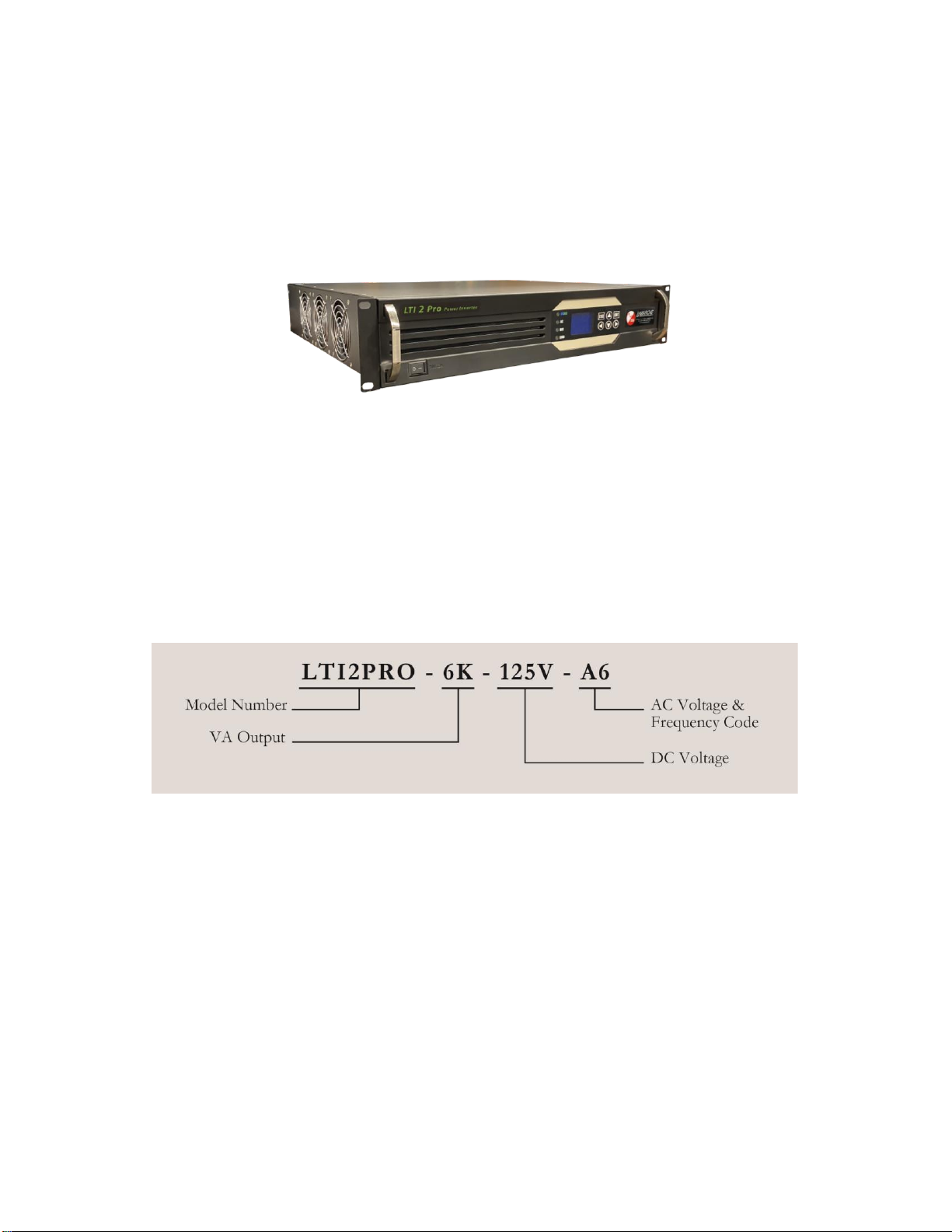
Model Scope/General Description ................................................................................................................1
Understanding the Model Number ...............................................................................................................1
Optional Accessories Included in the Inverter...............................................................................................1
1.0 Equipment Handling........................................................................................................................2
1.1 Storing the LTI2 PRO...................................................................................................................2
1.2 Moving the LTI2 PRO...................................................................................................................2
2.0 Installation.....................................................................................................................................2
2.1 Mounting the LTI2 PRO................................................................................................................2
2.1.1 Rack-Mounting the LTI2 PRO ................................................................................................3
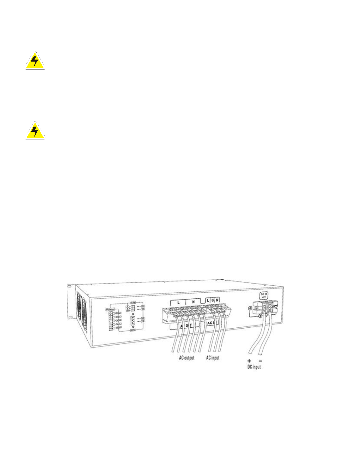
2.2 Electrical Connections ..................................................................................................................3
2.2.1 Input Wiring ........................................................................................................................4
2.2.2 Output Wiring......................................................................................................................4
2.2.3 Alarm Connections ...............................................................................................................5
3.0 Operation.......................................................................................................................................5
3.1 Operation Mode ..........................................................................................................................5
3.1.1 AC Power Supply Mode.........................................................................................................5
3.1.2 DC Power Supply Mode............................................................................................................5
3.2 Start-Up Sequence ......................................................................................................................6
3.2.1 Commissioning.....................................................................................................................6
3.2.2 Startup................................................................................................................................6
3.2.3 Shutdown .................................................................................................................................6
3.2.4 Mute ........................................................................................................................................6
3.3 Understanding the Alarms.................................................................................................................6
3.3.1 LED lights, LCD screen, and Buttons............................................................................................6
3.3.2 LED and Alarm Indications Details.............................................................................................7
3.3.3 LCD Menu...............................................................................................................................8
4.0 Troubleshooting...................................................................................................................................9
Appendix A: Technical Specifications ......................................................................................................... 10
Technical Specifications (Cont…)........................................................................................................... 11
Technical Specifications (Cont…)........................................................................................................... 12
Appendix B: Power Cabling Guide ............................................................................................................. 13
Appendix C: Manufacturer’s Warranty........................................................................................................ 14
Appendix D: Document Control and Revision History................................................................................... 15

iv
Table of Figures
Table 1 - Case and Weight .........................................................................................................................2
Table 2 - Wire Size Minimum Requirements .................................................................................................3
Table 3 - LED and Alarm Indications Details.................................................................................................7
Table 4 - Troubleshooting Guide .................................................................................................................9
Table 5 - Wire Size/Area Table.................................................................................................................. 13
Figure 1 - LTI2 Pro Overview ......................................................................................................................1
Figure 2 - Rack Mounting Brackets ..............................................................................................................3
Figure 3 - Rack Mounting ...........................................................................................................................3
Figure 4 - Input and Output Connections .....................................................................................................4
Figure 5 - Alarm Connections......................................................................................................................5
Figure 6 - AC inverter mode........................................................................................................................5
Figure 7 - DC dominated inverter mode .......................................................................................................5
Figure 8 - LED lights, LCD Screen and Button...............................................................................................6

1
Model Scope/General Description
The LTI2PRO series employs advanced SPWM and CPU control technology to realize precise control, isolated input
and output, output soft start, safety, and high efficiency with better reliability. The inverter is equipped with
standard features such as pure sine wave output, voltage regulation, under/over–voltage conditions, and overload
protection. The LTI2PRO Series is designed to operate at 125VDC input and produce 120 VAC nominal output
with 60HZ. The compact 2RU rack-mount enclosure is ideal for data centers, and telecommunications applications.
Understanding the Model Number
The LTI2PRO model number is coded to describe the features that are included. Find the model number on the
nomenclature nameplate of the enclosure. Follow the chart below to determine the configuration of the inverter.
Optional Accessories Included in the Inverter
This inverter may have been outfitted with a number of optional accessories or option packages. To determine
the options included (if any) refer to the cover page of the manual package. If the manual package that is included
with the inverter is no longer available, contact La Marche and provide the model or serial number to receive a
list of the included accessories.
Figure 1 - LTI2 Pro Overview

2
1.0 Equipment Handling
1.1 Storing the LTI2 PRO
If the LTI2 PRO is to be stored for more than a few days after delivery, it should be stored within its shipping
container. The location chosen for storage should be within an ambient temperature of -40 to 158° F (-40 to
70°C) with a non-condensing relative humidity of 0 to 95%. Storage should not exceed 2 years due to the limited
shelf life of the filter capacitors when they are not in service.
1.2 Moving the LTI2 PRO
After careful inspection and upon verification that the LTI2 PRO is undamaged, identify the enclosure style and
weight of the inverter. Refer to Table 1 below.
Output
VA
Output
Voltage
Output
Amps
Input
Voltage
Input
Current
Dimensions
(W x D x H) mm
Weight
LTI2 PRO
3kVA
120VAC
20A
125VDC
23.5A
16.1 x 13.7 x 3.5”
33 lbs
6kVA
120VAC
40A
125VDC
40.0A
16.1 x 19 x 3.5”
33 lbs
Table 1 - Case and Weight
2.0 Installation
2.1 Mounting the LTI2 PRO
Interchangeable mounting brackets are provided for 19” rack mounting. When mounting the LTI2 PRO in any
configuration, consider the size and weight of the Inverter. The rack must be able to support the weight of the
inverter, as well as an additional safety factor. Refer to Table 1 to verify the weight of the inverter. The location
chosen for the inverter should be within an ambient temperature range of -4˚F to 122˚F (-20˚C to 50˚C) with a
non-condensing relative humidity no higher than 95%. The inverter should be mounted in an area free of explosive
materials and away from any liquids. Avoid using equipment in a location with corrosive gases (e.g. over flooded
Lead Acid batteries) and dust. The LTI2PRO utilizes fan-assisted cooling, so clearance of at least 6 inches of free
air must be maintained in front and on top for proper cooling. Maintain 12 inches (300 mm) or more of clearance
at the rear of the inverter when rack mounting to allow for operation and maintenance. The preferred fastener is
a machine bolt backed with a flat washer, lock washer, and nut. All hardware should be corrosion-resistant.

3
2.1.1 Rack-Mounting the LTI2 PRO
The LTI2 PRO enclosure can be rack mounted on a standard 19/23” relay rack. For rack-mounting install the
brackets to the front of the LTI2 PRO enclosure, seen in Figure 2. Flush mount the LTI2 PRO enclosure to the
relay rack.
Figure 3 - Rack Mounting
2.2 Electrical Connections
Before beginning any work on the inverter, ensure that all incoming and output power is de-energized. Verify that
no voltage is present by using a voltmeter at all input and output terminals. Check that the voltage and frequency
match the inverter front nameplate specifications. Select wire size using the table below.
(All wires specified in the table are rated at 90 °C or 194 °F)
NOTE: These are the recommended sizes per La Marche Standards. The National Electrical Code (NEC) and
Local Wiring Codes must be followed.
Inverter
Rating
AWG Minimum
Wire Size for
DC Connection
AWG Minimum
Wire Size for
Equipment
Grounding
AWG Minimum
Wire Size for AC
Connection
LTI2 PRO-3K
#10
#14
#14
LTI2 PRO-6K
#8
#14
#14
Table 2 - Wire Size Minimum Requirements
Figure 2 - Rack Mounting Brackets

4
2.2.1 Input Wiring
WARNING:
Connecting the battery to the Inverter may cause a spark at the point of connection. There
is a RISK OF EXPLOSION in hazardous areas or locations where explosive gases have accumulated.
Access the rear of the inverter and locate the DC Input connection terminal. Connect DC wiring to the inverter
per figure-3. Refer to Table 2 for the recommended wire size.
WARNING:
Connect rated AC input to the Inverter, failure to properly rated input may cause a spark at
the point of connection.
Access the rear of the inverter and locate the AC Input connection terminal. Connect AC wiring to the inverter per
figure - 4. Refer to Table 2 for the recommended wire size.
With DC input wiring connected and operating within the DC range, verify inverter starts up by switching the
power switch to the front panel. The Inverter INV. ON LED should turn solid green, indicating successful start-up
and no faults. Using a digital multimeter, measure the AC output to verify voltage output.
2.2.2 Output Wiring
The LTI2PRO comes with Bulk AC connections at the rear of the inverter. Connect AC cables to the equipment
per the figure - 4. Select the recommended AC wire size using Table 2. If the distance between the inverter’s
output and the load exceeds 10 feet, use the Power Wiring Guide in Appendix B to minimize the voltage drop
across the wire distance.
Figure 4 - Input and Output Connections

5
2.2.3 Alarm Connections
The LTI2 PRO inverter is equipped with a single set of Form ‘C’ dry-type relay contacts (60 VDC @ 0.5A rating)
for Alarm.
Figure 5 - Alarm Connections
3.0 Operation
3.1 Operation Mode
3.1.1 AC Power Supply Mode
AC inverter working mode: Inverter employs mains for load when there are mains and switches to the inverter
when the mains is abnormal.
Figure 6 - AC Inverter Mode
3.1.2 DC Power Supply Mode
DC dominated inverter working mode: Under normal condition, DC-dominated inverter is under inverter output
status all the time; in case of DC fault, it switches to mains by-pass.
Figure 7 - DC Dominated Inverter Mode

6
3.2 Start-Up Sequence
3.2.1 Commissioning
Check whether the DC input voltage is consistent with the nameplate label; in case of any inconsistency, please
do not apply the DC power supply to an inverter, in order not to cause any damage! Check whether the wiring
polarity of the DC input is correct; or else, the inverter cannot be normally started. Check whether the wiring of
AC input and output is correct and confirm that there is no short circuit phenomenon.
If there is no error in the above checks, respectively apply DC power supply and AC power supply. Turn-on the
startup switch to power-up the inverter. Firstly, all LEDs perform a lamp test for self-inspection. Then, the output
relay is closed to output AC power to the load.
3.2.2 Startup
Confirm whether DC input and AC output of the power supply is correctly and reliably connected. After the pressing
power switch to rightwards, the inverter performs self-inspection. Before steady output, the inverter power supply
checks the external environment and checks whether the inverter supply power itself is normal; if various status
parameters of the inverter power supply and the mains are normal, the inverter will steady operate in mains
status or inverter status (AC-dominated inverter is steady in mains output status and DC-dominated inverter is
steady in inverter output status). It takes about 5 seconds to complete the startup process.
3.2.3 Shutdown
After the pressing power switch to leftwards, the inverter LED indicator light and the inverter power supplies are
turned off.
3.2.4 Mute
In the case of the inverter power supply faults, the system will send audible and visual alarm which can be set
through LCD, to the mute audible sound of a particular alarm, select Turn Off in the sound control option.
The operator can directly press ENT (temporary) button to inactivate and activate an audible alarm. For the
same alarm, the muted alarm will not be automatically turned on; if there is another alarm, no matter whether
the last alarm is under mute status or not, the system will automatically turn on the audible alarm.
3.3 Understanding the Alarms
3.3.1 LED lights, LCD screen, and Buttons
Figure 8 - LED lights, LCD Screen and Button

7
3.3.2 LED and Alarm Indications Details
Mode LED
Status
Indicator Light
Buzzer
AC Mode
Solid Green
No
DC Mode
Solid Blue
No
Load LED
Status
Indicator Light
Buzzer
Normal Load
Solid Green
No
Overload 120%
Slow Flashing Green
One Sound Every 1s
Overload 150%
Quick Flashing Green
One Sound Every 1s
Overload Shutdown
Slow Flashing Red
Continuous Sound
Short Circuit Shutdown
Quick Flashing Red
Continuous Sound
Inverter Fault
Solid Red
Continuous Sound
Mains LED
Status
Indicator Light
Buzzer
Normal AC Voltage
Solid Green
No
High AC Voltage
Quick Flashing Red
One Sound Every 3s
Low AC Voltage
Slow Flashing Red
One Sound Every 3s
No AC Voltage
Solid Red
One Sound Every 3s
Battery LED
Status
Indicator Light
Buzzer
Normal DC Voltage
Solid Green
No
High DC Voltage
Quick Flashing Red
One Sound Every 1s
Low DC Voltage
Slow Flashing Red
One Sound Every 3s
No DC Voltage
Solid Red
One Sound Every 3s
Table 3 - LED and Alarm Indications Details

8
3.3.3 LCD Menu
Figure 8 –LED and Alarm Indications Details
Figure 9 - LED and Alarm Indications Details

9
4.0 Troubleshooting
Table 4 - Troubleshooting Guide
Fault Type
Symptom
Possible Cause
Remedy
Startup fault
Inverse
Input
connection
Check the negative and positive
terminals of the DC input before
connection.
Confirm the negative and positive
terminal and then reconnect the
corresponding wire.
Low DC
Input
voltage
Use a Multimeter to measure the
voltages of the DC input to confirm
whether the voltage is higher than the
startup voltage.
Startup the inverter after the
battery is charged to the DC input
range.
Operating fault
Low-
voltage,
high-
voltage,
overload
protection.
Cut off the load to test whether the
inverter normally operates and the
voltage of each point is normal.
Consult with La Marche mfg.
Mains switching
fault
Too high or
too low
utility
supply
voltage
Use a Multimeter to measure the
voltages of the AC input to confirm
whether the voltage is within the
working range.
Switch after the utility supply
voltage is stable.
Low-voltage
shutdown
protection
of the
inverter
After the low-voltage shutdown of an
inverter, connect to the Mains without
switching.
Switch after the inverter operates
again.
Output fault
Inverter
protection
High voltage, low voltage, over-
temperature, overload.
Consult with La Marche mfg.
Communication
fault
Whether the
communicat
ion interface
is wrongly
accessed.
Check whether the correct
communication mode (RS232 or 485) is
selected.
Select correct communication
mode
Whether the
communicat
ion line is
too long.
Check whether the Baud rates of the
communication line material and panel
are consistent with each other.
Use twisted pair or reset Baud
rate.

10
Appendix A: Technical Specifications
The La Marche LTI2 PRO Inverter is designed for 1kVA to 6kVA with pure sine wave 120VAC 60Hz power at output from a 48V or 125V DC input source.
This inverter is equipped with standard features such as voltage regulation, under/over–voltage conditions, and overload protection with >=85% efficiency.
Parameter
LTI2 PRO
1K-48-
A6
LTI2PRO
2K-48-
A6
LTI2PRO
3K-48-
A6
LTI2PRO
3K-125-
A6
LTI2PRO
4K-48-
A6
LTI2PRO
4K-125-
A6
LTI2PRO
5K-48-
A6
LTI2PRO
5K-125-
A6
LTI2PRO
6K-125-
A6
Capacity
(VA)
1kVA
2kVA
3kVA
4kVA
5kVA
6kVA
DC
Input
Rated Input
Voltage (Vdc)
48V
48V
48V
125V
48V
125V
48V
125V
125V
Rated Input
Current (A)
20.8
41.6
62.5
27.2
83.3
36.3
106
45.45
54.54
Cut off- DC
Input Range
(Vdc)
40V-60V
40V-60V
40V-60V
90V-135V
40V-60V
90V-135V
40V-60V
90V-135V
90V-135V
Operating-
DC Input
Range (Vdc)
45.5V-57V
45.5V-57V
45.5V-57V
104V-
131V
45.5V-57V
104V-131V
45.5V-57V
104V-131V
104V-131V
Reflected
Noise Current
<=10%
AC
Bypass
Input
Bypass
Voltage
Range (Vac)
85V-135V (+/-10V)
AC
Output
Rated Output
Capacity (W)
800
1600
2400
3200
4000
4800
Output
Voltage and
Frequency
120Vac, 60Hz
Output
Current (A)
6.7
13.3
20
27
33.3
40

11
Technical Specifications (Cont…)
AC Output
Voltage Accuracy (V)
120±1.5%
Frequency Accuracy (Hz)
60±0.1%
Waveform
Pure sine wave
Total harmonic distortion
(THD)
≤3% (linear load)
Dynamic response time
5% (load 0←→100%)
Power factor (PF)
0.8
Overload capacity
110%-130% 60s
131%-150% 10s
Inversion efficiency
(80% resistive load)
≥85%
Inverter - Bypass (ms)
≤8ms
Working
Environment
Dielectric Strength
(input & output)
1500Vac, 1 minute
Noise (1m)
≤55dB
Ambient temperature
-20℃~+50℃
Humidity
0~90%, No condensation
Altitude (m)
≤2000
Indication
LCD Status
Input and Output Voltage, Frequency, Output Current
Inverter Status
Normal mains, Normal Inversion, Battery Under-Voltage,
and Output Overload
Measurement
Size (D×W×H)
16.1 x 13.7 x 3.5”
16.1 x 19 x 3.5”
Protection function
Input under-voltage and overvoltage, output overload
and short circuit protection, etc.

12
Technical Specifications (Cont…)
PROTECTION
Current Walk-In
The output current will gradually increase after the inverter is turned on,
eliminating surges and overshoot
Current Limit
Overload protection
Temperature
Over Temperature Shutdown Protection
ENVIRONMENTAL
Operating
Temperature
32 to 122˚F (0 to 50˚C)
Relative Humidity
0 to 95% (non-condensing)
Cooling
Fan Assisted
Shock
The inverter in its shipping container withstands shock developed when one edge
of the container is dropped six inches while the opposite edge is resting on the
ground, or it is dropped two inches without any physical damage or degradation
of the electrical performance.
Vibration
The inverter in its shipping contained, withstands vibration encountered in
shipping without physical damage or degradation of the electrical performance.
Altitude
The inverter is capable of operation at altitudes up to 2000 meters at an ambient
temperature of up to +40 degrees C.
Ventilation
The unit should be mounted so that ventilating openings are not blocked and air
entering the cabinet does not exceed 50 degrees C (122 degrees F).

13
Appendix B: Power Cabling Guide
Use the following formulas and table to determine proper wire size for minimal voltage drop. At distances
exceeding 10 feet, the DC wire size should be chosen to keep the voltage difference between the inverter’s DC
input terminals and the battery at less than 1/2 volt when the inverter is fully loaded.
Table of Conventions:
CMA = Cross-section of wire in circular MIL area
A= Ultimate drain in amperes
LF = Conductor loop feet
MaxAmp= Maximum allowable amperes for given voltage drop
AVD = Allowable voltage drop
K = 11.1 for commercial (TW) copper wire
= 17.4 for aluminum
Calculating Wire Size Requirements:
AVD KLFA
CMA
=
Calculating Current Carrying Capacity of Wire:
KLF AVDCMA
MaxAmp
=
Size
(AWG)
Area
CIR.MILS
Size
(MCM)
Area
CIR.MILS
18
1620
250
250000
16
2580
300
300000
14
4110
350
350000
12
6530
400
400000
10
10380
500
500000
8
16510
600
600000
6
26240
700
700000
4
41740
750
750000
3
52620
800
800000
2
66360
900
900000
1
83690
1000
1000000
0
105600
1250
1250000
00
133100
1500
1500000
000
167800
1750
1750000
0000
211600
2000
2000000
Table 5 - Wire Size/Area Table

14
Appendix C: Manufacturer’s Warranty
All La Marche Manufacturing Co. equipment has been thoroughly tested and found to be in proper operating
condition upon shipment from the factory and is warranted to be free from any defect in workmanship and
material that may develop within one (1) year from date of purchase under normal use.
If the equipment proves defective within a one year period, it shall be replaced without charge after examination
at our factory, providing such defect in our opinion, is due to faulty material or workmanship and not caused by
tampering, abuse, misapplication, or improper installation.
Should the equipment require major replacement or repair, the equipment must be returned to the La Marche
factory to have the inspections, parts, replacements, and testing performed by factory personnel. Should it be
necessary to return a piece of equipment to the factory, the customer or Sales representative must first obtain
an RMA (Return Material Authorization) from the factory. If upon inspection at the factory, the defect was due to
faulty material or workmanship, all repairs will be made at no cost to the customer during the warranty period.
All internal maintenance to be performed by La Marche.
La Marche reserves the right to honor the warranty with a replacement unit.
In accepting delivery of the equipment, the purchaser assumes full responsibility for proper installation, installation
adjustments, and service arrangements. Should minor adjustments be required, the local La Marche Sales
Representative should be contacted to provide this service.
All sales are final. Only standard La Marche units will be considered for return. A 25% restocking fee is charged
when return is a factory authorized. Special units are not returnable.
In no event shall La Marche Manufacturing Co. have any liability for consequential damages, or loss, damage, or
expense directly or indirectly arising from the use of the products, or any inability to use them either separately
or in combination with other equipment or materials, or from any other cause. In addition, any alterations of
equipment made by anyone other than La Marche Manufacturing Co. render this warranty null and void.
La Marche Manufacturing Co. reserves the right to make revisions in the current production of equipment and
assumes no obligation to incorporate these revisions in earlier models.
The failure of La Marche Manufacturing Co. to object to provisions contained in customers' purchase orders or
other communications shall not be deemed a waiver of the terms or conditions hereof, nor acceptance of such
provisions.
The above warranty is exclusive, supersedes, and is instead of all other warranties, expressed or implied, including
any implied warranty of merchantability or fitness. No person, agent, or dealer is authorized to give any warranties
on behalf of the Manufacturer, nor to assume for the Manufacturer any other liability in connection with any of
its products unless made in writing and signed by an official of the manufacturer.

15
Appendix D: Document Control and Revision History
Part Number: 143460
Instruction Number: P25-LLTI2PRO-1
Issue ECN: 22666 -09/20
22666 - 09/20
Table of contents
Other Lamarche Inverter manuals
Popular Inverter manuals by other brands

Terrasmart
Terrasmart TerraGlide installation manual

DEVA Broadcast
DEVA Broadcast DB9000-STC instruction manual

Minarik
Minarik MM21051C user manual

Solax
Solax X-Hybrid user manual

MULTIQUIP
MULTIQUIP WHISPERWATT DCA-45SSIU3 Operation and parts manual

Generac Power Systems
Generac Power Systems RV 45 SERIES owner's manual