Progressive Dynamics PD1610 User manual

Consult a licensed electrician or RV technician for installation assistance 814420H
Quick Reference Guide for
PD1600 Series Inverter
© 2022 Progressive Dynamics Enterprises, LLC. All rights reserved.
I. LIMITED WARRANTY: Progressive Dynamics warrants its power inverters to be free from defects in material or workmanship under normal use and service;
and limits the remedies to repair or replacement.
II. DURATION: This warranty shall extend for a period of two years from the original date of purchase, and is valid only within the continental limits of the
United States and Canada.
III. WARRANTY EXCLUSIONS: This warranty does not apply to:
A. Any product which has been repaired or altered in any way by an unauthorized person or service station
B. Damage caused by excessive input voltage, misuse, negligence, or accident; or an external force
C. Any product which has been connected, installed, or adjusted or used other than in accordance with the instructions furnished, or has had the serial number
altered, defaced, or removed
D. Cost of all services performed in removing and reinstalling the power inverter
E. ANY LOST PROFITS, LOST SAVINGS, LOSS OF USE OF ENJOYMENT OR OTHER INCIDENTAL DAMAGES ARISING OUT OF THE USE OF,
OR INABILITY TO USE, THE PRODUCT. THIS INCLUDES DAMAGES TO PROPERTY AND, TO THE EXTENT PERMITTED BY LAW, DAM-
AGES FOR PERSONAL INJURY. THIS WARRANTY IN IN LIEU OF ALL OTHER WARRANTIES, INCLUDING WARRANTIES OF MER-
CHANTABILITY AND FITNESS FOR A PARTICULAR PURPOSE.
IV. PROOF OF PURCHASE: A warranty claim must be accompanied by proof of the date of purchase.
V. CLAIM PROCEDURE: Upon discovery of a defect, Progressive Dynamics shall be supplied the following information a the address listed below:
A. Name and address of claimant
B. Name, model, and serial number of the product
C. Application in which product was installed. (Included manufacturer, model, and model year where applicable)
D. Date of purchase
E. Complete description of the claimed defect
Upon determination that a warranty claim exists (a defect in material or workmanship occurring under normal use and service) the inverter shall be shipped postage
prepaid to Progressive Dynamics together with proof of purchase. The product will be repaired or replaced and returned postage prepaid.
Mail Returns to: Progressive Dynamics
507 Industrial Road
Marshall, MI 49068
For Warranty Service service@progressivedyn.com
For Full User’s Manual Please Visit:
https://www.progressivedyn.com/service/installation-guides/
Member
See website www.progressivedyn.com
for more trouble shooting information and return instructions
Record the unit’s model and serial number in case you need provide this information in the future. It is much easier to record this
information now, instead of trying to gather it after the unit has been installed.
Model: Serial Number:
PD1610_ (1000 Watt)
PD1618_ (1800 Watt)
PD1620_ (2000 Watt)

Consult a licensed electrician or RV technician for installation assistance 814420H
The PD1600 series inverter comes with a remote display and a 50 ft long connection cable included. The Remote Display is designed for
use with only PD1600 series inverters. The remote will allow complete monitoring of your inverter. This guide will help you install and use
the inverter and the remote control, to monitor the functions.
Materials List
The inverter unit package includes the following items:
(1) PD1600 series inverter remote inverter remote
(1) Owner’s guide & mounting template
(1) Connection cable - (50 ft long connection cable included
with inverter)
NOTE:
If any of the items are missing, contact Progressive Dynamics for replacement.
Use only a cable provided by PDI. DO NOT use a cable that is not designated
for that specific unit.
Included Items & Connecting the Remote
Figure 1 Inverter Remote (Communication cable not shown. 50 ft long cable included standard)
Connecting the remote to the inverter
Plug the connector plug into the port on the top of the inverter and the back of the remote control using the supplied communication
cable (see Figure 2). Failure to use a communication cable provided by PDI may result in damage to the remote display.
It is recommended that you install the remote into the designated location prior to connecting the cable to the remote and the inverter.
Please refer to the installation portion of this guide for those instructions.
Figure 2 Connecting communication cable
Verifying connection
Once the remote display is securely con-
nected to the inverter and the inverter is
turned on, it will begin displaying readouts
immediately. If your remote control display
does not begin to display information, con-
firm that the communication cable is se-
curely connected into both ports on the in-
verter and the remote control.
NOTICE: EQUIPMENT DAMAGE
This Quick Reference Guide is in addition to, and incorporated by reference, the relevant product information for each product in the
PD1600 series inverter. Before reviewing this guide, you must read the relevant product manual. Unless specified, information on safety,
specifications, installation, and operation is as shown in the primary documentation. Ensure you are familiar with that information before
proceeding.
PD1600 series remote displays are compatible ONLY with PD1600 series inverters. Attempting to use a remote display not designated for
that specific inverter could cause damage to the unit and the remote display.
Failure to follow these instructions will result in your inverter to not function properly.
PD1600 Series
Remote Display
(NOTE: REMOTE ACTUALLY
SMALLER THAN INVERTER UNIT)
(NOTE: REMOTE ACTUALLY
SMALLER THAN INVERTER UNIT)

Consult a licensed electrician or RV technician for installation assistance 814420H
WARNING: FIRE HAZARD
DC Input wiring must be protected with properly sized circuit protec-
tion (fuses or circuit breakers).
Never operate the inverter without properly connecting the equipment
ground.
Tighten the nuts on terminals properly. Loose connections cause exces-
sive voltage drop and may cause overheated wires and melted insula-
tion. DO NOT under tighten the screw on the terminal lugs. This will
cause the wires to lose connection.
Failure to follow these instructions may result in serious injury or
death. Failure to follow these instructions may also damage the
unit and/or equipment.
Mounting Instructions
WARNING: FIRE, SHOCK, AND ENERGY HAZARD
Inverter should only be installed by an electrician or a certified RV
technician.
Inverter is NOT ignition protected. Do not mount in the LP gas or bat-
tery compartments.
Inverter should be mounted in a dry, well ventilated space with ade-
quate air flow.
Failure to follow these instructions may result in serious injury or
death. Failure to follow these instructions may also damage the unit
and/or equipment.
Mounting Instructions
Inverter may be installed horizontally or vertically. Vertical
installations should be sure to protect the inverter from for-
eign debris falling inside the unit through the fan openings.
External strain relief should be used for DC input wires.
Inverter can be secured to a flat surface using the side
mounting slots. See Figure 3 and Figure 4 for mounting hole
pattern.
Inverter should be located in a well ventilated compartment.
Minimum compartment dimensions provide 2” of space
above the inverter display and open on the electrical connec-
tion side. Operation in high ambient temperatures require
additional ventilation space.
NOTICE: EQUIPMENT DAMAGE
Do not connect any AC source (such as generator or utility power) to
the AC output wiring of the inverter. Connecting an AC source to the
AC Output of the inverter will result in hazardous conditions.
DO NOT disassemble the inverter. It does not contain any user service-
able parts. Attempting to service the unit yourself could result in an
electrical shock or burn.
Failure to follow these instructions may damage the unit and/or
equipment.
Figure 3:PD1610 Mounting Hole Pattern Figure 4:PD1618/PD1620 Mounting Hole Pattern
Consult a licensed electrician or RV technician for installation assistance 814420H
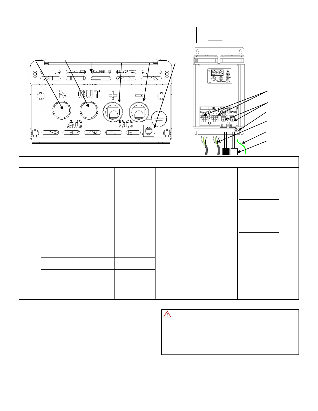
Electrical Connection Instructions
ELECTRICAL CONNECTION INFORMATION
DC
WIRING
PD1610(1kW)
WIRE LENGTH MIN. WIRE SIZE STRIP LENGTH CONNECTION INFO
0-5 ft. #2 AWG
Strip 3/4” (19 mm) insulation from each
cable prior to installation. Do not leave
excess copper exposed.
Tighten lugs to a torque of
100 in-lbs (11.3 N-m).
Do not over tighten.
Fuse: min. 100A for full load
(See NEC for safety codes)
5-10 ft. #1 AWG
10-15 ft. #1/0 AWG
PD1618(1.8kW) 0-10 ft. #2/0 AWG Strip 3/4” (19 mm) insulation from each
cable prior to installation. Do not leave
excess copper exposed.
Tighten lugs to a torque of
200 in-lbs (22.6 N-m).
Do not over tighten.
Fuse: min. 200A for full load
(See NEC for safety codes)
PD1620(2kW) 0-10 ft. #2/0 AWG
PD1610(1kW) 0-100 ft. #14 AWG Solid
Strip 0.6” (15 mm) insulation from each
wire prior to installation. Do not leave
excess copper exposed.
Standard 3/8” trade strain
relief . No torque wrench re-
quired
AC
WIRING PD1618(1.8kW) 0-100 ft. #14 AWG Solid
PD1620(2kW) 0-100 ft. #12 AWG Solid
GND
WIRING PD1600 Series Any #8 AWG
Strip 0.5” (13 mm) insulation from each
wire prior to installation. Do not leave
excess copper exposed.
Torque ground lug to 30-50 in
-lbs.
NOTE: To ensure optimum performance all input wires should be as short as possible. Failure to meet minimum recommended wire size will result in reduced performance
WARNING: FIRE, SHOCK, AND ENERGY HAZARD
Make sure wiring is disconnected from all electrical sources before
handling. All wiring must be done in accordance with local and na-
tional electrical wiring codes.
Failure to follow these instructions may result in serious injury or
death.
Electrical Connection Instructions
1. Ensure all power sources are disconnected from the inverter
2. Remove the wiring cover
3. Remove AC Input knockouts and AC Output knockouts
4. Install 3/8” strain relief in AC Input and AC Output ports
5. Connect AC Out terminal block (Ground, Neutral, and Line)
6. Connect AC In terminal block (Ground, Neutral, and Line)
7. Tighten strain relief (if applicable)
8. Connect DC terminals (positive and negative) to battery with properly sized wires, 5/32” hex (PD1610); 1/4” hex (PD1618/20)
9. When connecting DC wires a small spark may occur. This is normal charging of the inverter’s internal capacitors
10. Provide external strain relief for DC wires
11. Connect equipment ground stud to a grounding point (typically the vehicle’s chassis ) using a 5/32” hex key
12. Re-install the wiring cover
Figure 4
Electrical Connections
Top View
Figure 5 Electrical Connections Side View
PD1600 series inverters are compatible with
BOTH lithium and lead acid batteries.
DC Wiring
Ground Wiring
NOTE:
For PD1600J series, use pre-installed power cord to
connect AC-IN when connecting AC power.
AC Wiring
DC Lugs
Ground Lug
AC Terminal
Blocks
AC Input Wiring
Cover
AC Output Negative DC
Connection
Positive DC
Connection
Equipment
Ground

Consult a licensed electrician or RV technician for installation assistance 814420H
Inverter Display Panel
Figure 6 Inverter on-board Display Panel
Display Features
Power Button: Press to turn on; hold to turn off
Select Button: Cycles between display states:
Input Voltage, Output Voltage, Output
Power, Standby, Error Code (if applicable)
Power Indicator: Lights up green when the inverter is on
Shore Indicator: Lights up yellow when AC input is detected
Low Bat Warning Indicator: Lights up red when the battery
is nearing the end of its charge
PDI Remote Port for externally mounted display
RV-C Port for communication with a RV-C compatible hub
Select
Button Display
Power
Button
PDI Remote Port
(use with PD1601)
RV-C Port
(use with RV-C
Compatible Device)
Figure 7 Inverter Remote Display
Figure 8 Display Indicator (Inverter on-board and remote control)
Power Indicator Shore Power IndicatorLow Bat Warning Indicator Fault Indicator
ERROR CODES
Error Code Condition Action
E-1 Low battery
voltage detected
Re-charge the battery
Check DC cable size
Tighten DC connections
E-2 High battery
voltage shutdown
Disconnect external sources (alternator
or charger)
E-3 AC output
overload
shutdown
Evaluate the loads connected to the AC
outlet of the unit. Loads may need to be
reduced.
E-4 Over-temperature
shutdown
Reduce load to the AC output
Ensure that the inverter is in a dry, well
ventilated space with adequate air flow
Ambient temperature may be too high
E-5 Internal Error Ensure all connections are tightened
Contact the PDI Service Department
E-6 Short Circuit
Look for damaged AC loads
Look for faulty AC wiring
Evaluate peak power requirements for
all loads
E-7 DC Voltage
Failure
Ensure DC connections are tightened
Ensure battery has sufficient capacity
Review minimum wire length and size
requirements

Consult a licensed electrician or RV technician for installation assistance 814420H
Inverter Specifications
*All ratings at 25 °C unless otherwise listed
SPECIFICATIONS
PHYSICAL SPECIFICATIONS TRANSFER SWITCH
PD1610 PD1618 PD1620 PD1610 PD1618 PD1620
Dimensions
L:11.2”(284mm)
W:6.7”(170mm)
H:4.0”(101mm)
L:15.0”(381mm)
W:7.9”(200mm)
H:4.0”(101mm)
L:15.0”(381mm)
W:7.9”(200mm)
H:4.0” (101mm)
Transfer Voltage 95 - 135 VAC
Transfer Time < 50 msec
Net Weight 7 lbs (3.2 kg) 11 lbs (5.0 kg) 11 lbs (5.0 kg) Pass Through
Ampacity 20 AAC 30 AAC
AC OUTPUT DC INPUT
PD1610 PD1618 PD1620 PD1610 PD1618 PD1620
Waveform Pure Sine Wave Nominal Voltage 12.0 VDC
Output
Voltage 120 VAC Under-Voltage
Shutdown 10.5 VDC
Max Power
(Cont) 1000W 1800W 2000W Under-Voltage
Restart 12.0 VDC
Max Power
(Peak) 2000W 3600W 4000W Over-Voltage
Shutdown 15.5 VDC
Frequency 60 Hz Over-Voltage
Restart 15.0 VDC
Peak
Efficiency 90% Max Current @
max load 100 ADC 180 ADC 200 ADC
Installing the remote display on the wall
1. Place the template on the wall (See Figure 10).
2. Measure and mark the wall for the opening to be cut for re-
mote control.
3. Mark the corners of the recess outline on the wall.
4. Measure and mark the two mounting holes for the two
screws on the wall.
5. Cut along the recess outlines on the wall to make a hole for
the remote control.
6. Pre-drill the mounting holes appropriate for mount screws
(not provided) that will be used.
7. Connect the communication cable to the RJ9 port on the in-
verter and the remote control (see Figure 2).
8. Mount the remote panel unit on the wall.
Note:
Ensure that there are no
Obstructions present, such as:
- Pipes
- Insulation
- Electrical Wiring
Ensure that there is at least 1” (25.4 mm) of space for communication cable.
Figure 9
Mounting Diagram
Recommended GFCI for use with PD1610 Inverter:
Leviton GFTR2 (20A), Eaton SGF20 (20A), Bestten USP-20A-20-PKB (20A), Hongki TST20 (20A),
Zhangjiagang City Barep Technology Co. YGH-094 (20A),
Recommended GFCI for use with PD1618/20 Inverter:
Siemens QF130A (30A)

Consult a licensed electrician or RV technician for installation assistance 814420H
Installation Template
Figure 10 Remote Display Mounting Template
[69.89] 2.75
[57.15] 2.25
MOUNTING
HOLE
MOUNTING
HOLE
[101.64] 4.00
[85.85] 3.38
[73.03] 2.87
(Full Scale)

Consult a licensed electrician or RV technician for installation assistance 814420H
P r o g r e s s i ve D y n a m ic s, I n c .
507 Industrial Rd
Marshall, MI 49068
Visit us on the web for other great products.
www.progressivedyn.com
This manual suits for next models
5
Table of contents
Other Progressive Dynamics Inverter manuals

Progressive Dynamics
Progressive Dynamics PD1600 Series User manual

Progressive Dynamics
Progressive Dynamics PD1210SV Operating instructions

Progressive Dynamics
Progressive Dynamics PD1200 Series User manual

Progressive Dynamics
Progressive Dynamics PD1200 Series Operating instructions

Progressive Dynamics
Progressive Dynamics PD1600 Series Operating instructions

Progressive Dynamics
Progressive Dynamics PD1618 Series Operating instructions


