MEIDEN THYFREC-VT240S User manual

———————— NOTICE ————————
1. Read this manual thoroughly before using the VT240S, and store in a safe place
for reference.
2. Make sure that this manual is delivered to the final user.
MEIDENSHA CORPORATION
MEIDEN
AC SPEED CONTROL EQUIPMENT
THYFREC-VT240S
200V System 0.75 to 90kW Normal Duty
400V System 0.75 to 475kW Normal Duty
Sep. 2006ST-3450
INSTRUCTION MANUAL
Công ty TNHH điện tửcông nghiệp RITECH
Chuyên cung cấp dịch vụsửa chữa: biến tần, Servo, Máy CNC, Khởi động mềm...
Hotline hỗtrợkỹthuật: 0979578581
Website: ritech.vn
Với đội ngũkỹthuật lâu năm kinh nghiệm trong nghềtrực tiếp sửa chữa không qua trung gian

i
Contents
Preface ..................................................................................................................................... iii
PRECAUTIONS FOR SAFETY ................................................................................................ iv
<Names of each part> ............................................................................................................. viii
Chapter 1 Delivery Inspection and Storage ........................................................................ 1-1
1-1 Delivery inspection and storage ................................................................................... 1-1
1-2 Details of rating nameplate and type display method.................................................. 1-1
Chapter 2 Installation and Wiring......................................................................................... 2-1
2-1 Installation environment ............................................................................................... 2-1
2-2 Installation and wiring method...................................................................................... 2-3
2-3 Precautions for power supply and motor wiring........................................................... 2-5
2-4 Precautions for wiring to the control signal .................................................................. 2-16
Chapter 3 Test Operation and Adjustment ......................................................................... 3-1
3-1 Flow of test operation ................................................................................................... 3-2
3-2 Preparation before turning power ON .......................................................................... 3-3
3-3 Control modes .............................................................................................................. 3-4
3-4 Automatic tuning and test operation ............................................................................ 3-5
Chapter 4 Operation Panel.................................................................................................... 4-1
4-1 Outline of operation panel types and functions............................................................ 4-1
4-2 Various operations and displays when LCD panel is connected ................................ 4-6
4-3 Various operations and displays when LED panel is connected................................. 4-14
4-4 Customizing block-B, C parameter .............................................................................. 4-25
4-5 Changing modes .......................................................................................................... 4-27
Chapter 5 Control Input/Output............................................................................................ 5-1
5-1 Input/output terminal function....................................................................................... 5-1
5-2 Control input/output circuit............................................................................................ 5-2
5-3 Programmable sequence input function (PSI) ............................................................. 5-3
5-4 Programmable sequence output function (PSO)......................................................... 5-8
5-5 Sequence input logic .................................................................................................... 5-9
5-6 Changing of terminal functions..................................................................................... 5-10
5-7 Programmable input function (PI) ................................................................................ 5-12
5-8 Programmable output function (P0) ............................................................................. 5-16
5-9 Selecting the setting data............................................................................................. 5-20
Chapter 6 Control Functions and Parameter Settings ...................................................... 6-1
6-1 Monitor parameters ...................................................................................................... 6-1
6-2 Block-A parameters...................................................................................................... 6-8
6-3 Block-B parameters...................................................................................................... 6-10
6-4 Block-C parameters...................................................................................................... 6-42
6-5 Block-U parameters...................................................................................................... 6-60
6-6 Function explanation .................................................................................................... 6-76
6-7 Setting the overload mode .......................................................................................... 6-167
6-8 Adjusting the IM vector control speed control related parameters .............................. 6-169
6-9 Adjusting the PM motor control system parameters.................................................... 6-174

ii
6-10 Operating the auxiliary drive motor .............................................................................. 6-182
6-11 Built-in PLC Function.................................................................................................... 6-185
6-12 Explanation of standard serial and Modbus communication ....................................... 6-192
Chapter 7 Options .................................................................................................................. 7-1
7-1 Outline of options.......................................................................................................... 7-1
7-2 Built-in PCB option ..................................................................................................... 7-5
7-3 Dynamic braking (DB) option ....................................................................................... 7-7
7-4 ACL and DCL ............................................................................................................... 7-11
7-5 EMI filter........................................................................................................................ 7-17
Chapter 8 Maintenance and Inspection............................................................................... 8-1
8-1 Inspection items............................................................................................................ 8-1
8-2 Measuring devices ....................................................................................................... 8-4
8-3 Protective functions ...................................................................................................... 8-5
8-4 Troubleshooting with fault display................................................................................ 8-6
8-5 Troubleshooting with no fault display........................................................................... 8-15
Chapter 9 Compatible Standards ......................................................................................... 9-1
9-1 UL/cUL Standards ........................................................................................................ 9-1
9-2 CE Marking................................................................................................................... 9-5
Appendix 1 Type Description System ................................................................................. A-1
Appendix 2 Outline Dimension Drawings ........................................................................... A-10
Appendix 3. Fault Codes ....................................................................................................... A-12
Appendix 4. Display Messages ............................................................................................ A-14
Appendix 5. Segment LED Display ...................................................................................... A-15
Revision history........................................................................................................................ R-1

iii
Preface
Thank you for purchasing the “Meiden AC Speed Control Equipment THYFREC-VT240S”.
THYFREC-VT240S is a highly functional inverter that is easy to use.
Please read this manual thoroughly before use, and keep the manual at hand for later
reference. Also make sure that this manual is delivered to the final users.
WARNING
ALWAYS READ THIS MANUAL THOROUGHLY BEFORE USING THE VT240S.
THIS INVERTER CONTAINS HIGH VOLTAGE CIRCUITS THAT MAY BE FATAL TO HUMANS. USE
EXTREME CAUTION DURING INSTALLATION. MAINTENANCE MUST BE PERFORMED BY
QUALIFIED TECHNICIANS, AND ALL POWER SOURCES MUST BE DISCONNECTED BEFORE ANY
MAINTENANCE. SUFFICIENT NOTICE MUST BE GIVEN TO THE GENERAL OPERATORS AND
WORKERS BEFORE STARTING.
• ELECTRIC SHOCK MAY OCCUR IF THE FOLLOWING POINTS ARE NOT OBSERVED.
(1) DO NOT OPEN THE FRONT COVER WHILE THE POWER IS ON.
(2) A CHARGE STILL REMAINS IN THE INVERTER WHILE THE INDICATOR IS LIT EVEN IF THE
POWER HAS BEEN TURNED OFF. DO NOT OPEN THE FRONT COVER IN THIS CASE. WAIT
AT LEAST 20 MINUTES AFTER THE INDICATOR GOES OUT.
(3) DO NOT CONTACT THE ELECTRICAL CIRCUIT WHILE THE "CHARGE" LED ON THE UNIT IS
LIT. PERFORM SERVICING, ETC., AFTER WAITING AT LEAST 20 MINUTES AFTER THE
LAMP GOES OUT.
(4) ALWAYS GROUND THE INVERTER CASE. THE GROUNDING METHOD MUST COMPLY WITH
THE LAWS OF THE COUNTRY WHERE THE INVERTER IS BEING INSTALLED.
• THE INVERTER MAY BE DESTROYED BEYOND REPAIR IF THE FOLLOWING POINTS ARE NOT
OBSERVED.
(1) OBSERVE THE INVERTER SPECIFICATIONS.
(2) CONNECT ADEQUATE CABLES TO THE INPUT/OUTPUT TERMINALS.
(3) ALWAYS KEEP THE INVERTER INTAKE/OUTTAKE PORTS CLEAN, AND PROVIDE ENOUGH
VENTILATION.
(4) ALWAYS OBSERVE THE CAUTIONS LISTED IN THIS INSTRUCTION MANUAL.
• THERE MAY BE SOURCES OF NOISE AROUND THIS INVERTER AND MOTOR DRIVEN BY
THIS INVERTER. CONSIDER THE POWER SUPPLY SYSTEM, INSTALLATION PLACE AND
WIRING METHOD BEFORE INSTALLATION.
INSTALL THIS INVERTER AWAY FROM DEVICES THAT HANDLE MINUTE SIGNALS, SUCH AS
MEDICAL EQUIPMENT IN PARTICULAR. ALSO SEPARATE THE DEVICES ELECTRICALLY,
AND TAKE SUFFICIENT NOISE MEASURES.
• TAKE SUFFICIENT SAFETY MEASURES WHEN USING THIS INVERTER FOR PASSENGER
TRANSPORTATION, SUCH AS IN LIFTS (ELEVATORS).
• LONGEVITY MIGHT BECOME REMARKABLY SHORT BY THE TEMPERATURE CHANGE’S
BY THE CURRENT OF THE REPETITION ALWAYS JOINING IN THE POWER DEVICE WHEN
USED BY THE USAGE WITH HIGH REPETITION FREQUENCY OF DRIVING AND THE STOP
(ELEVATOR AND CRANE, ETC.).
WHEN USED BY SUCH A USAGE, DIRATING (FRAME RAISING OF THE INVERTER, CURRENT
DECREASE WHEN STARTING AND STOPPING, AND DECREASE OF THE CAREER FREQUENCY)
IS NEEDED.
PLEASE INQUIRE SEPARATELY ABOUT DETAILS.

iv
PRECAUTIONS FOR SAFETY
Items to be observed to prevent physical damage or property damage and to ensure safe use of this product
are noted on the product and in this instruction manual.
●Please read this instruction manual and enclosed documents before starting operation to ensure correct
usage. Thoroughly understand the device, safety information and precautions before starting operation.
After reading, always store this manual where it can be accessed easily.
●The safety precautions are ranked as "DANGER" and "CAUTION" in this instruction manual.
!DANGER : When a dangerous situation may occur if handling is mistaken leading
to fatal or major injuries.
CAUTION : When a dangerous situation may occur if handling is mistaken leading
to medium or minor injuries, or physical damage.
Note that some items described as CAUTION may lead to major results depending on the
situation. In any case, important information that must be observed is described.
●This instruction manual is written on the premise that the user has an understanding of the inverter.
Installation, operation, maintenance and inspection of this product must be done by a qualified person.
Even qualified persons must undergo periodic training.
Qualified refers to satisfying the following conditions.
○The person has thoroughly read and understood this instruction manual.
○The person is well versed in the installation, operation, maintenance and inspection of this product, and
understands the possible dangers.
○The person is informed on matters related to starting, stopping, installation, locks and tag displays, and
has been trained in the operation and remedies.
○The person has been trained on the maintenance, inspection and repairs of this product.
○The person has been trained on protective tools used to ensure safety.

v
1. Transportation and installation
CAUTION
• Always transport the product with an appropriate amount according to the products weight.
Failure to observe this could lead to injuries.
• Install the inverter, dynamic braking unit and resistor, and other peripheral devices on
non-combustible material such as metal.
Failure to observe this could lead to fires.
• Do not place the product near inflammable items.
Failure to observe this could lead to fires.
• Do not hold the front cover while transporting the product.
Failure to observe this could lead to injuries from dropping.
• Do not let conductive materials such as screws or metal pieces and inflammable materials such as oil
enter the product.
Failure to observe this could lead to fires.
• Install the product in a place that can withstand the weight of the product, and follow the instruction
manual.
Failure to do so could lead to injuries from dropping.
• Do not install and operate an inverter that is damaged or that has missing parts.
Failure to observe this could lead to injuries.
• Always observe the conditions described in the instruction manual for the installation environment.
Failure to observe this could lead to faults.
2. Wiring
!DANGER
• Always turn the device's input power OFF before starting wiring.
Failure to do so could lead to electric shocks or fires.
• Carry out grounding that complies with the standards of the country where the inverter is being
installed.
Failure to do so could lead to electric shocks or fires.
• When using the PM motor, even if the inverter is stopped, the voltage will be generated at the output
terminal (U, V, W) during rotation. Always carry out wiring while the motor is stopped.
Failure to do so could lead to electric shocks or injuries.
• Wiring must always be done by a qualified electrician.
Failure to observe this could lead to electric shocks or fires.
• Always install the device before starting wiring.
Failure to do so could lead to electric shocks or injuries.
• Prepare a breaker such as an MCCB or fuses that matches the capacity for the inverter's power supply
side.
Failure to do so could lead to fires.
CAUTION
• Do not connect an AC power supply to the output terminals (U, V, W).
Failure to observe this could lead to injuries or fires.
• Confirm that the product's rated voltage and frequency match the power supply voltage and frequency.
Failure to do so could lead to injuries or fires.
• Install an overheating protection device on the dynamic braking unit and resistor, and shut off the
power with this fault signal.
Failure to do so could lead to fires in the event of abnormal overheating.
• Do not directly connect a resistor to the DC terminals (between L+1, L+2, and L–).
Failure to observe this could lead to fires.
• Tighten the terminal screws with the designated tightening torque.
Failure to do so could lead to fires.
• Correctly connect the output side (U, V, W).
Failure to do so could cause the motor to rotate in reverse and the machine to be damaged.
• Always correctly connect when using the encoder.
The signal polarity specifications differ according to the encoder. With reference to the item of a test
operation, please be alike with a parameter setup (C51) and adjust signal polarity more.
Failure to observe this could lead to reverse rotation or abnormal acceleration of the motor, and to
injuries or machine damage.

vi
3. Operation
!DANGER
• Always install the front cover before turning the input power ON. Never remove the cover while the
power is ON. There are sections in the front PCB that are charged with high voltages.
Failure to observe this could lead to electric shocks.
• Never touch the switches with wet hands.
Failure to observe this could lead to electric shocks.
• Never touch the inverter’s terminals while the inverter power is ON even if the operation is stopped.
Failure to observe this could lead to electric shocks.
• Selection of the retry function could lead to unexpected restarting when alarm stops. The machine
may start suddenly if the power is turned ON when the automatic start function is selected. Do not
go near the machine.
(Design the machine so that physical safety can be ensured even if the machine restarts.)
Failure to do so could lead to injuries.
• The machine may not stop when a stop command is issued if the deceleration stop function is
selected and the overvoltage/overcurrent limit function is activated. Prepare a separate emergency
stop switch.
Failure to do so could lead to injuries.
• The unit will not suddenly restart even if the alarm is reset with the operation signal input, however,
in order to prevent unexpected operation, ensure that the operation signal is no longer being input,
and reset the alarm.
Failure to do so could lead to injuries.
CAUTION
• The heat sink and dynamic braking resistor are heated to high temperatures, so never touch them.
Failure to observe this could lead to burns.
• Do not block the inverter’s ventilation holes.
Failure to observe this could lead to fires.
• The inverter operation can easily be set from low speeds to high speeds, so confirm that the
operation is within the tolerable range for the motor or machine before making settings.
Failure to do so could lead to injuries.
• Prepare holding brakes when necessary. Holding is not possible with the inverter’s brake functions.
Failure to do so could lead to injuries.
• Confirm the operation of the motor as a single unit before operating the machine.
Failure to do so could lead to injuries or machine damage due to unforeseen movements.
Always prepare a safety backup device so that the machine is not placed in a hazardous situation
when an error occurs in the inverter.
Failure to do so could lead to injuries or machine damage or fires.
• Please do not detach the operation panel while the inverter power is ON. Please detach the
operation panel in the state of power supply OFF. When the operation panel is installed while the
inverter power is ON, the microcomputer of the inverter is occasionally reset.

vii
4. Maintenance, inspection and part replacement
!DANGER
• Always wait at least 20 minutes after turning the input power OFF before starting inspections.
Wait at least 20 minutes after turning the input power OFF before starting work. Make sure that the
displays on the operation panel have gone out before removing the front cover.
Remove the front cover, and confirm that the "CHARGE" LED on the unit has gone out. Also check
that the voltage between terminals L+1 or L+2 and L– is 15V or less before starting the inspections.
(Check with the "CHARGE" LED if the unit is not provided with the L– terminal.)
Failure to observe this could lead to electric shocks.
• Maintenance, inspections and part replacement must be done by a designated person.
(Remove all metal accessories such as watches, bracelets, etc., before starting the work.)
(Always use an insulation measure tool.)
Failure to observe this could lead to electric shocks and injuries.
• Always turn the power OFF before inspecting the motor or machine. A potential is applied on the motor
terminal even when the motor is stopped.
Failure to do so could lead to electric shocks and injuries.
• Do not use parts other than those designated for the replacement parts.
Contact your inverter dealer for replacement parts.
Failure to observe this could lead to fires.
CAUTION
• Vacuum the inverter with a vacuum cleaner to clean it. Do not use water or organic solvents.
Failure to observe this could lead to fires or damage.
5. Others
!DANGER
• Never modify the product.
Failure to observe this could lead to electric shocks or injuries.
CAUTION
• Dispose of this product as industrial waste.

viii
<Names of each part>
Cooling fan installation case
For 018L, 030H and smaller
The presence and quantity of cooling fans will differ according to the capacity.
For 022L and larger, 037H and larger
1. Delivery Inspection and Storage
1 – 1
Chapter 1 Delivery Inspection and Storage
1-1 Delivery inspection and storage
(1) Remove the inverter from the packaging, and check the details on the rating nameplate to confirm
that the inverter is as ordered. The rating nameplate is on the left side of the unit.
(2) Confirm that the product has not been damaged.
(3) If the inverter is not to be used for a while after purchasing, store it in a place with no humidity or
vibration in the packaged state.
(4) Always inspect the inverter before using after storing for a long period. (Refer to 8-1.)
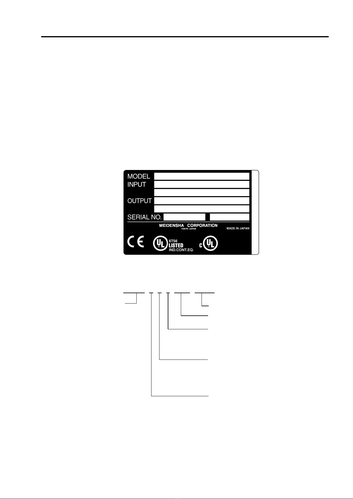
1-2 Details of rating nameplate and type display method
(1) The following details are listed on the rating nameplate.
(Note 1) Refer to Chapter 9 for details on UL Instruction.
(2) Using the above type as an example, the type is displayed as follows:
VT240S-2P2H BF2V R 0 X 0 0 0
Input voltage and capacity
(Refer to Appendix 1)
VT240S-2P2HBF2-VR0X000
AC3PH 380-480V 50/60Hz
HD: 5.4A / ND: 8.6A
AC3PH 380-480V 0.1-440Hz
HD: 5.4A / ND: 8.6A
1234567890 001 01 A
Meidensha control No.
Indicates the control PCB option.
(Refer to Table 7-1-a.)
Indicates the operation panel selection.
0 : None
1 : LCD type
2 : LED type
Indicates the main circuit option.
(Refer to 7-4, 5.)
0 : Standard
F : Internal noise filter
R : With DCL
Indicates the main circuit option 1
(Refer to 7-3)
A : Standard (no options)
B : With dynamic braking resistor
2. Installation and Wiring
2 – 1
Chapter 2 Installation and Wiring
CAUTION
• Always transport the product with an appropriate amount according to the products weight.
Failure to observe this could lead to injuries.
• Install the inverter, dynamic braking unit and resistor, and other peripheral devices on
non-combustible material such as metal.
Failure to observe this could lead to fires.
• Do not place the product near inflammable items.
Failure to observe this could lead to fires.
• Do not hold the front cover while transporting the product.
Failure to observe this could lead to injuries from dropping.
• Do not let conductive materials such as screws or metal pieces and inflammable materials such as oil
enter the product.
Failure to observe this could lead to fires.
• Install the product in a place that can withstand the weight of the product, and follow the instruction
manual.
Failure to do so could lead to injuries from dropping.
• Do not install and operate an inverter that is damaged or that has missing parts.
Failure to observe this could lead to injuries.
• Always observe the conditions described in the instruction manual for the installation environment.
Failure to observe this could lead to faults.
2-1 Installation environment
Observe the following points when installing the inverter.
(1) Install the inverter vertically so that the cable lead-in holes face downward.
(2) Make sure that the ambient temperature is –10°C to 50°C. (Refer to Appendix 1.)
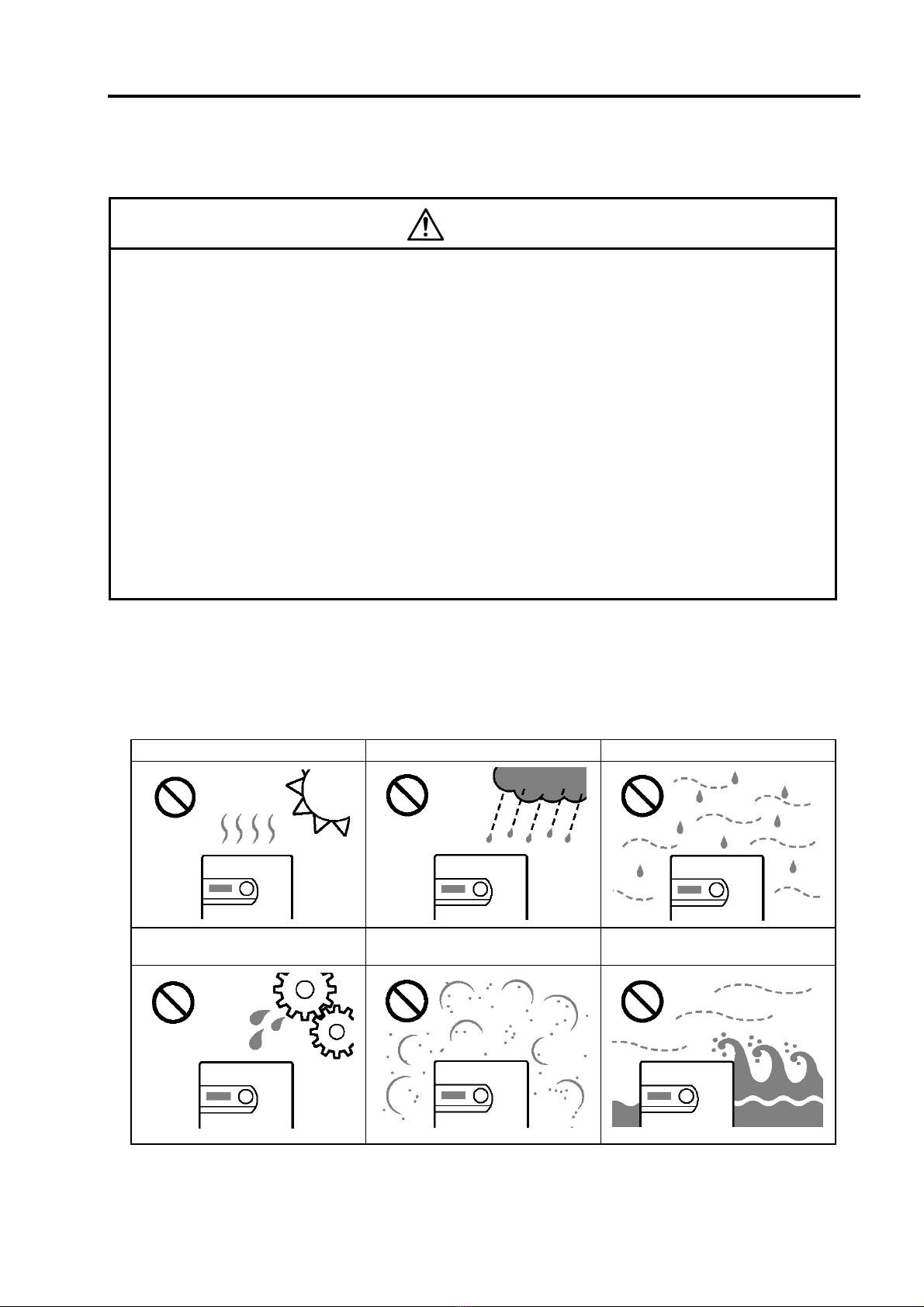
(3) Avoid installation in the following environment.
Place subject to direct sunlight Place subject to wind, rain or water Place with high levels of humidity
Place subject to oil drops Place where dust, cotton lint or iron
chips, etc., are present Place with high levels of salt
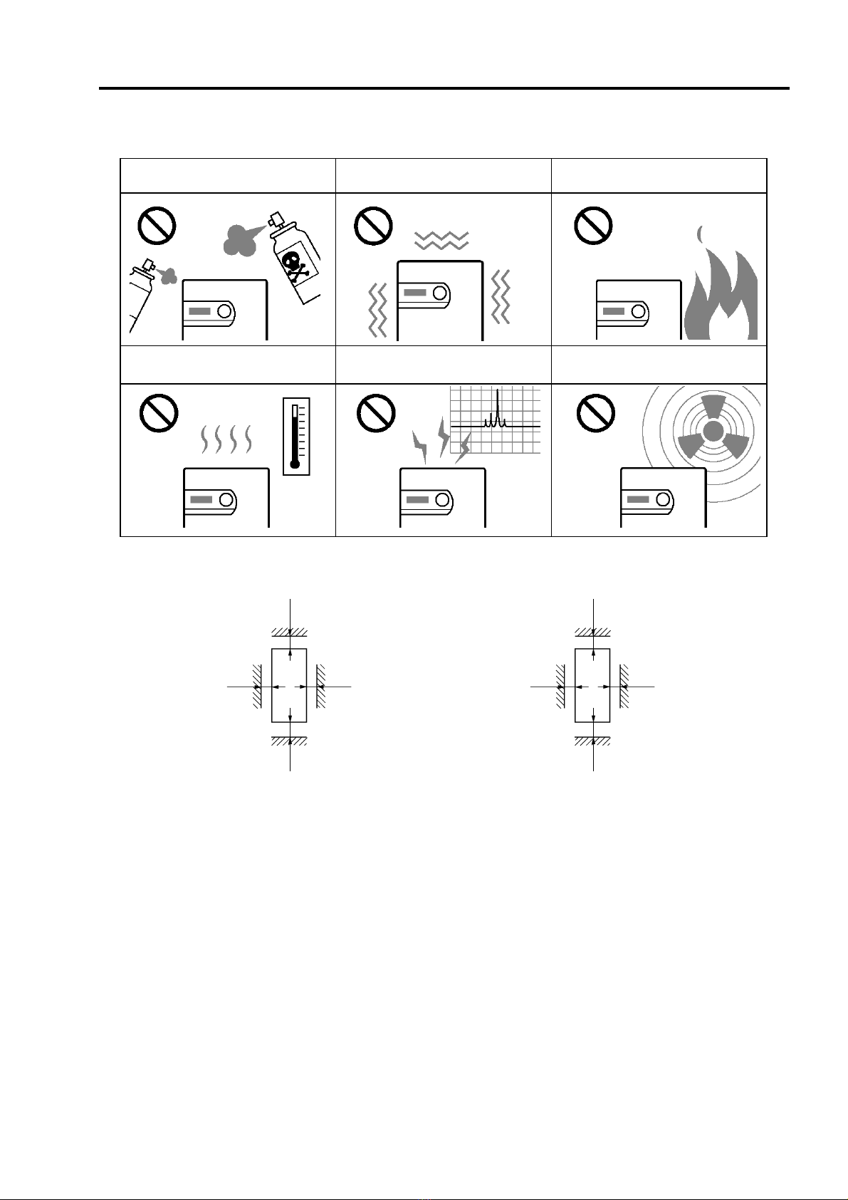
2. Installation and Wiring
2 – 2
Place with harmful corrosive or
explosive gases or fluids are present
Place near sources of vibration such
as dollies or press machines
Place where flammable materials
are present
Place with high levels of ambient
temperature
Places with high levels of magnetic
noise
Places where radioactive
substances are present
(4) Ensure ventilation space around the inverter. (Refer to Fig. 2-1.)
VT240S
200mm150mm
50mm50mm
VT240S
200mm200mm
50mm50mm
For 018L, 030H and smaller For 022L, 037H and larger
Fig. 2-1

2. Installation and Wiring
2 – 3
2-2 Installation and wiring method
Installation and wiring for the 018L and 030H and below,
and the wiring for the 022L and 037H and above are
carried out with the front cover removed. The operation
panel is fixed with the latches for the operation panel
mounting holder, so the front cover can be removed with
the operation panel attached.
To remove the operation panel, securely hold the panel
with a thumb on the lower side and another finger on the
top side as shown on the right, and pull the panel forward
and off. To mount the operation panel, hold it the top and
bottom sides with five fingers, and press the panel on
horizontally. Confirm that the operation panel is securely
fixed with the latches for the operation panel mounting
holder.
(1) 018L, 030H and smaller (Fig. 2-2-a)
Fix the VT240S at four places when installing. The lower two installation sections are notched.
Remove the front cover, and wire to the main circuit and control terminal block.
VT240S mounting hole
(total 4 bolts)
Cooling fan installation case

2. Installation and Wiring
2 – 4
(2) 022L, 037H and larger (Fig. 2-2-b)
Fix the VT240S at four places when installing. The VT240S mass is more than 25kg, so installation
by two workers is recommended. When two workers are installing the unit, they should confirm each
step with signals. Wire in the same manner as step (1).
VT240S mounting hole
(total 4 bolts)

2. Installation and Wiring
2 – 5
2-3 Precautions for power supply and motor wiring
!DANGER
• Always turn the device's input power OFF before starting wiring.
Failure to do so could lead to electric shocks or fires.
• Carry out grounding that complies with the standards of the country where the inverter is being
installed.
Failure to do so could lead to electric shocks or fires.
• When using the PM motor, even if the inverter is stopped, the voltage will be generated at the output
terminal (U, V, W) during rotation. Always carry out wiring while the motor is stopped.
Failure to do so could lead to electric shocks or injuries.
• Wiring must always be done by a qualified electrician.
Failure to observe this could lead to electric shocks or fires.
• Always install the device before starting wiring.
Failure to do so could lead to electric shocks or injuries.
• Prepare a breaker such as a non-fuse breaker (MCCB) or fuse that matches the capacity for the
inverter's power supply side.
Failure to do so could lead to fires.
CAUTION
• Do not connect an AC power supply to the output terminals (U, V, W).
Failure to observe this could lead to injuries or fires.
• Confirm that the product's rated voltage and frequency match the power supply voltage and frequency.
Failure to do so could lead to injuries or fires.
• Install an overheating protection device on the dynamic braking resistor, and shut off the power with an
error signal.
Failure to do so could lead to fires in the event of abnormal overheating.
• Do not directly connect a resistor to the DC terminals (between L+1, L+2 and L–).
Failure to observe this could lead to fires.
• Tighten the terminal screws with the designated tightening torque.
Failure to do so could lead to fires.
• Correctly connect the output side (U, V, W).
Failure to observe this could lead to reverse rotation of the motor, and to injuries or machine
damage.
• Always correctly connect when using the encoder.
The signal polarity specifications differ according to the encoder. With reference to the item of a test
operation, please be alike with a parameter setup (C50,C51) and adjust signal polarity more.
Failure to observe this could lead to reverse rotation or abnormal acceleration of the motor, and to
injuries or machine damage.
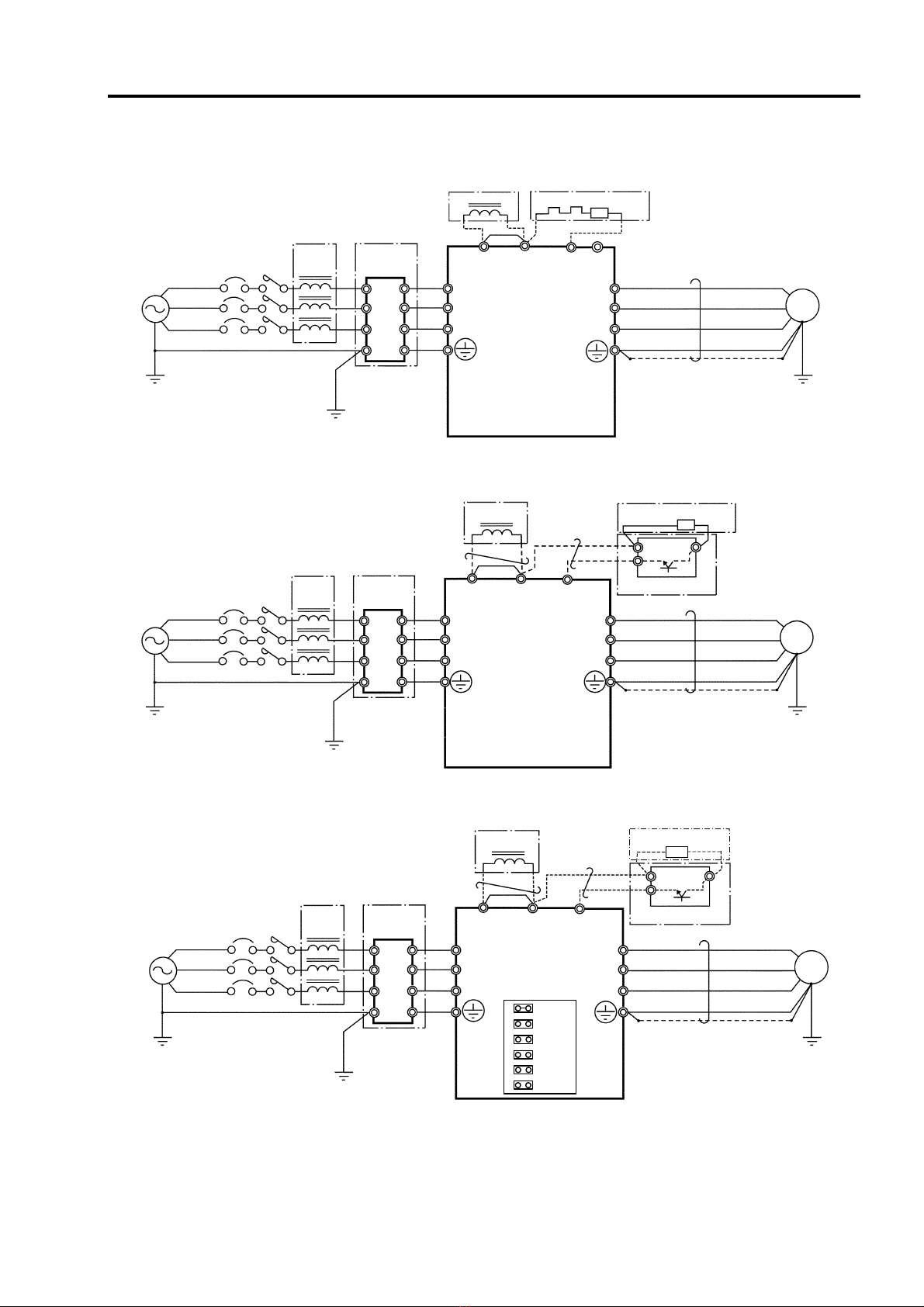
Refer to Fig. 2-3-a and wire the main circuits for the power supply and motor, etc.
Always observe the following precautions for wiring.
CAUTION
There is a risk of electric shocks.
The VT240S has a built-in electrolytic capacitor, so a charge will remain even when the inverter power
is turned OFF. Always observe the followings before carrying out wiring work.
• Wait at least 20 minutes after turning the power OFF before starting work. Make sure that the
displays on the operation panel have gone out before removing the cover.
• After removing the cover, confirm that the "CHARGE" LED in the unit has gone out. Also check that
the voltage between terminals L+1 or L+2 and L– is 15V or less before starting the wiring work.
(Check with the "CHARGE" LED if the unit is not provided with the L– terminal.)
2. Installation and Wiring
2 – 6
(a) 018L, 022H and smaller
1 4
2 5
3 6
E E
L+1 B
MCCB (Note 1)
U
V
W
(Note 1)
L1
L2
L3
L+2
DCL
L-
VT240S M
MC
(Note 3)
(Note 9)
(Note 10)
76D DB resistor
(Note 11)
(Note 6)
(Note 5)
(Note 8)
Noise filter
(Note 7)
ACL
(Note 6)
(Note 9)
(Note 2)
Power supply
(Note 13) (Note 12)
(
Note 15
)
(Note 7)
(b) 022L to 090L, 030H to 055H
VT240S M
1 4
2 5
3 6
E E
N
P DB
L+2L+1 L
−
MCCB MC
(Note 3)
(Note 9)
(Note 7)
(Note 10)
DB resistor
DCL
(Note 11)
(Note 6)
(Note 5)
DB unit
(Note 8) (Note 1)
U
V
W
(Note 1)
L1
L2
L3
Noise filter
(Note 7)
ACL
(Note 6)
(Note 9)
(Note 2)
Power supply
(Note 13)
(Note 12)
(c) 075H to 475H
DCL
1 4
2 5
3 6
E E
M
L-
N
DB
P
L+2L+1
VT240S
MCCB
U
V
W
(Note
1)
L1
L2
L3
(注 13)
(注 13) 76D
MC
JP-380
JP-400
JP-415
JP-440
JP-460
JP-480
MC
(Note 3)
(Note 9)
(Note 7)
(Note 10)
(Note 11)
(Note 6)
(Note 5)
DB unit
(Note 8)
Noise filter
(Note 7)
ACL
(Note 6)
(Note 9)
(Note 2)
Power supply
(Note 13)
(Note 12)
DB resistor
(Note 1)
(Note 4)
Fig. 2-3-a Example of main circuit wiring
2. Installation and Wiring
2 – 7
(Note 1) Configuration of inverter's main circuit
The inverter input terminals are L1, L2 and L3. The output terminals to the motor are U, V and
W. Do not connect the power supply to the U, V, W terminals. Incorrect wiring will lead to
inverter damage or fires.
The VT240S main circuit configuration is largely divided into three types according to the
capacity zone.
(1) The first type is the 011L/015H and smaller capacities. The L+1 and L+2 terminals are
located in the step before the pre-charge circuit. The DB circuit is built-in, and the use of
the built-in DB resistor can be selected with options. The use of the built-in EMC filter can
also be selected with options. Note that the external EMC filter must be used for the 7P5L
and 011L capacity.
With the 011L/015H and smaller capacity, the L+2 and L- terminals for connecting the
PWM converter are provided as a standard. When using the PWM converter, refer to the
DC Input Option Supplement Manual. Prepare a D-type option for all other capacities.
(2) The second type is the 015L, 018L/018H, and 022H capacities. The L+1 and L+2
terminals are located in the step after the pre-charge circuit. The DB circuit is built-in, but
the DB resistor must be prepared by the customer. With the 018H and 022H capacities,
the use can be selected with the built-in EMC filter options. Use an external EMC filter
with the 015L and 018L capacities.
(3) The third type is the 022L/030H and larger capacities. The L+1 and L+2 terminals are
located in the step after the pre-charge circuit. The built-in DCL can be selected as an
option. A standalone DCL can also be selected. With the 030H, the use of the built-in
EMC filter can be selected with options. Use an external EMC filter with the 022L/037H
and larger capacities.
*1) Incompatible with 7P5L and 011L
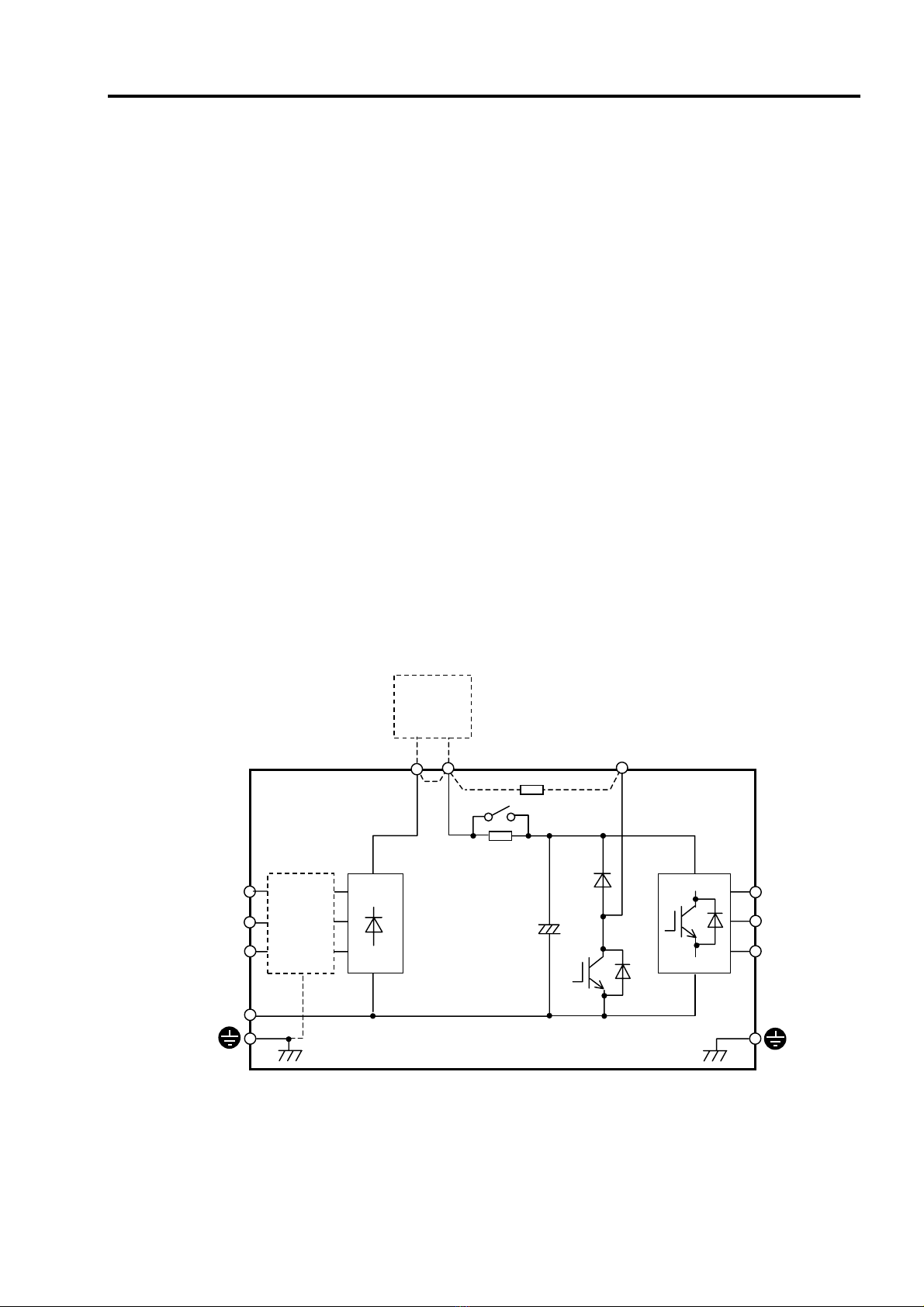
(1) 011L/015H and smaller capacities
L+1 L+2 B
L1
L2
L3
U
V
W
Standalone
DC reactor
(option)
L-
Built-in DB resistor
(option)
VT240S
Built-in
EMC filter
(option)
*1

2. Installation and Wiring
2 – 8
*2) Incompatible with 015L and 018L
(2) 015L, 018L/018H, 022H
*3) Only standalone type is available for 030H
*4) Only compatible with 030H
(3) 022L/030H and larger capacities
L+1 L+2
L1
L2
L3
U
V
W
A
dditional/
standalone
DC reactor
(option) *3
L-
VT240S
Built-in
EMC
filter
(option)
*4
Standalone
DB unit
(option)
L+1 L+2 B
L1
L2
L3
U
V
W
Standalone
DC reactor
(option)
VT240S
External DB resistor
(p
re
p
ared b
y
customer
)
Built-in
EMC
filter
(option)
*2

2. Installation and Wiring
2 – 9
(Note 2) Wire size
Use wires having the wire size shown in Table 2-3-a and Table 2-3-b for the main circuit wiring
shown in Fig. 2-3-a.
Table 2-3 gives the screw sizes, applicable wire sizes and tightening torque for the main circuit
terminal shown in Fig. 2-3-b.
Table 2-3-a Terminal and applicable wire (for normal-duty)
Power supply, motor, DCL wiring DB wiring
Wire size Tightening torque Wire size Tightening torque
Inverter type
VT240S-
Terminal
screw size AWG mm2N • m lb-in
Terminal
screw
size AWG mm2N • m lb-in
0P7L M4 14 2.1 1.2
10.6 M4 14 2.1 1.2
10.6
1P5L M4 14 2.1 1.2
10.6 M4 14 2.1 1.2
10.6
2P2L M4 14 2.1 1.2
10.6 M4 14 2.1 1.2
10.6
4P0L M4 10 5.3 2.0
17.7 M4 14 2.1 2.0
17.7
5P5L M4 8 8.4 2.0
17.7 M4 14 2.1 2.0
17.7
7P5L M5 8 8.4 2.0
17.7 M5 14 2.1 2.0
17.7
011L M5 6 13.3 4.5
39.8 M5 14 2.1 4.5
39.8
015L M6 3 26.7 9.0
79.6 M6 14 2.1 9.0
79.6
018L M8 2 33.6 9.0
79.6 M8 12 3.3 9.0
79.6
022L M8 1 42.4 9.0
79.6 M8 10 5.3 9.0
79.6
030L M8 2/0 67.4 9.0
79.6 M8 10 5.3 9.0
79.6
037L M10 4/0 107.0 18.0
159.3 M5 6 13.3 18.0
159.3
045L M10
1/0 ×2 53.5 ×2 28.9 255.7 M5 (L-)
M10 (L+2) 6 13.3 2.5
28.9
22.1
255.7
055L M10
1/0 ×2 53.5 ×2 28.9 255.7 M5 (L-)
M10 (L+2) 6 13.3 2.5
28.9
22.1
255.7
075L
090L
0P7H M4 14 2.1 1.2 10.6 M4 14 2.1 1.2 10.6
1P5H M4 14 2.1 1.2 10.6 M4 14 2.1 1.2 10.6
2P2H M4 14 2.1 1.2 10.6 M4 14 2.1 1.2 10.6
4P0H M4 14 2.1 1.2 10.6 M4 14 2.1 1.2 10.6
5P5H M4 12 3.3 1.2 10.6 M4 14 2.1 1.2 10.6
7P5H M4 10 5.3 2.0 17.7 M4 14 2.1 2.0 17.7
011H M4 8 8.4 2.0 17.7 M4 14 2.1 2.0 17.7
015H M5 8 8.4 2.0 17.7 M5 14 2.1 2.0 17.7
018H M5 6 13.3 2.0 17.7 M5 14 2.1 2.0 17.7
022H M5 6 13.3 4.5 39.8 M5 14 2.1 4.5 39.8
030H M6 4 21.2 9.0 79.6 M6 12 3.3 9.0 79.6
037H M8 2 33.6 9.0 79.6 M8 10 5.3 9.0 79.6
045H M8 1 42.4 9.0 79.6 M8 6 13.3 9.0 79.6
055H M8 1/0 53.5 18.0 159.3 M8 6 13.3 18.0 159.3
075H
090H
110H
132H
160H
200H
250H
315H
400H
475H

2. Installation and Wiring
2 – 10
Table 2-3-b Terminal and applicable wire (for heavy-duty)
Power supply, motor, DCL wiring DB wiring
Wire size Tightening torque Wire size Tightening torque
Inverter type
VT240S-
Terminal
screw size AWG mm2N • m lb-in
Terminal
screw
size AWG mm2N • m lb-in
0P7L M4 14 2.1 1.2
10.6 M4 14 2.1 1.2 10.6
1P5L M4 14 2.1 1.2
10.6 M4 14 2.1 1.2 10.6
2P2L M4 14 2.1 1.2
10.6 M4 14 2.1 1.2 10.6
4P0L M4 14 2.1 2.0
17.7 M4 14 2.1 2.0 17.7
5P5L M4 10 5.3 2.0
17.7 M4 14 2.1 2.0 17.7
7P5L M5 8 8.4 2.0
17.7 M5 14 2.1 2.0 17.7
011L M5 8 8.4 4.5
39.8 M5 14 2.1 4.5 39.8
015L M6 6 13.3 9.0
79.6 M6 14 2.1 9.0 79.6
018L M8 3 26.7 9.0
79.6 M8 14 2.1 9.0 79.6
022L M8 2 33.6 9.0
79.6 M8 12 3.3 9.0 79.6
030L M8 1 42.4 9.0
79.6 M8 10 5.3 9.0 79.6
037L M10 2/0 67.4 18.0
159.3 M5 10 5.3 18.0 159.3
045L M10 4/0 107.0 28.9
255.7 M5 (L-)
M10 (L+2) 6 13.3 2.5
28.9
22.1
255.7
055L M10
1/0 × 2 53.5 × 228.9 255.7 M5 (L-)
M10 (L+2) 6 13.3 2.5
28.9
22.1
255.7
075L
090L
0P7H M4 14 2.1 1.2 10.6 M4 14 2.1 1.2 10.6
1P5H M4 14 2.1 1.2 10.6 M4 14 2.1 1.2 10.6
2P2H M4 14 2.1 1.2 10.6 M4 14 2.1 1.2 10.6
4P0H M4 14 2.1 1.2 10.6 M4 14 2.1 1.2 10.6
5P5H M4 14 2.1 1.2 10.6 M4 14 2.1 1.2 10.6
7P5H M4 12 3.3 2.0 17.7 M4 14 2.1 2.0 17.7
011H M4 10 5.3 2.0 17.7 M4 14 2.1 2.0 17.7
015H M5 8 8.4 2.0 17.7 M5 14 2.1 2.0 17.7
018H M5 8 8.4 2.0 17.7 M5 14 2.1 2.0 17.7
022H M5 6 13.3 4.5 39.8 M5 14 2.1 4.5 39.8
030H M6 6 13.3 9.0 79.6 M6 14 2.1 9.0 79.6
037H M8 4 21.2 9.0 79.6 M8 12 3.3 9.0 79.6
045H M8 2 33.6 9.0 79.6 M8 10 5.3 9.0 79.6
055H M8 1 42.4 18.0 159.3 M8 6 13.3 18.0 159.3
075H
090H
110H
132H
160H
200H
250H
315H
400H
475H
Table of contents


