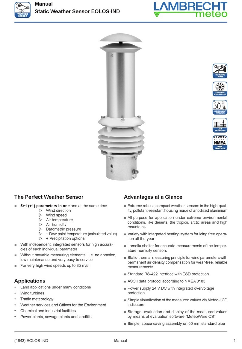
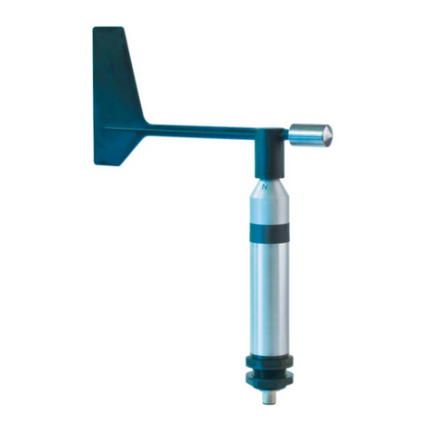
Lambrecht EFFICIENT Modbus User manual

Manual
Wind Sensors EFFICIENT Modbus (14579)
(14579) EFFICIENT Modbus Manual
EFFICIENT Modbus · The Ecient Solution
Are you cost-conscious but still demanding when it comes to
your wind measurement data?
Then the EFFICIENT Modbus sensors are your ideal solution.
With this sensor concept, high-quality materials meet func-
tional design. EFFICIENT sensors also impress with their
high accuracy, eortlessly simple mounting principles and
corrosion-resistant materials. EFFICIENT sensors save time
and money, but not the quality of your measurement data.
• Proven sensor technology
• Very good starting values
• Simple mast mounting
POSSIBLE APPLICATIONS
► Professional meteorological applications
► Building automation
► Photovoltaic systems
► Industrial meteorology
1

Manual
Wind Sensors EFFICIENT Modbus (14579)
(14579) EFFICIENT Modbus Manual
Disposal
LAMBRECHT meteo GmbH is listed and registered at the Stiftung Elektro-Altgeräte Register ear under:
WEEE-Reg.-No. DE 45445814
In the category of monitoring and control instruments, device type: “Monitoring and control instruments for exclusively com-
mercial use”.
Within the EU
The device has to be disposed according to the European Directives 2002/96/EC and 2003/108/EC (Waste Elec-
trical and Electronic Equipment). Do not dispose the old device in the household waste! For an environmentally
friendly recycling and disposal of your old device, contact a certied disposal company for electronic waste.
Outside the EU
Please follow the regulations in your country regarding the appropriate disposal of waste electronic equipment.
Content
1 Initial operation 3
2 Principles of installation 3
3 Setting up the North direction
of the wind direction sensor 4
4 Electrical connection 4
5 Heating 4
6 Maintenance 4
7 Wiring diagram 5
8 Dimensional drawings 6
9 Modbus data protocols EFFICIENT Modbus 7
9.1 General 7
9.2 Data encoding 7
9.3 Standard conguration - Default 7
9.4 Available Modbus commands 7
9.5 Instantaneous values / realtime values (Input Register) 8
9.6 Period data - Average, maximum and minimum (Input Register) 8
9.7 Descriptive sensor parameter registers (Holding Register) 9
9.8 Conguration registers (Holding Register) 9
9.9 Autoconguration 9
10 Technical data 10
2

Manual
Wind Sensors EFFICIENT Modbus (14579)
(14579) EFFICIENT Modbus Manual
1 Initial operation
Wind can be represented by a vector quantity. For a complete
description of the wind it is necessary to specify its speed and
direction. The two components are subject to spatial and tem-
poral variations; thus, strictly speaking, they are valid only for
the site where the measuring instrument is put up. We therefore
recommend to select the place of installation very carefully.
Selecting the place of installation
Generally, wind measuring instruments should not measure
the specic wind conditions of a limited area, but indicate the
typical wind conditions of a wider area. The values measured
at dierent places must be comparable. Thus, when installing
the sensor you should make sure the place of installation is
not under the lee of great obstacles. The distance between the
obstacles and the sensor should be 10 times the height of the
obstacles (this corresponds to the denition of an undisturbed
terrain).
If an undisturbed terrain of this kind does not exist the sensor
must be put up at a height of at least 5 m above the obstacle
height.
If the sensor must be installed on a roof top the place of instal-
lation must be in the middle of the roof to avoid predominant
wind directions. If you want to measure both wind direction
and wind speed, install the sensors at the same measuring
point, if possible, and make sure to avoid any mutual inu-
ence of the sensors. A wind sensor pair easily meets this
requirement since the sensors are set up side by side. Their
horizontal distance should be approximately 1.5 m. The two
sensors must be staggered vertically so that the lower edge of
the upper wind speed sensor is 0.1 to 0.5 m above the upper
edge of the lower wind direction sensor.
2 Principles of installation
Because the installation takes place in a danger-
ous height, the assembly personal must follow
the rules for prevention of accidents.
I. Traverse with bore (e.g. Id-No. 32.14627.010000)
Material thickness for installation of the sensor between the
nuts may be max. 10 mm.
2. The sensor is led without cable into the bore and fastened
by the opposite side with the loose nut.
3. Attach the sensor with the at side of detached nut from
the lower side. Tighten with a suitable tool (wrench size
36), until a twisting safety of the sensor aligned to the north
is given.
II. Mast or pipe mounting
Make sure the device is easily accessible so that you
can set up the north direction for the wind direction
sensor and perform any maintenance work. To reach
the sensors use a ladder of the appropriate length
or a telescoping working platform of the appropriate
height.
Ladders or other lifting helps must be absolutely
in order and must be guarantee a secure support!
Follow the rules for prevention of accidents.
Mount the sensors at the top of grounded tube with an outer
diameter Ø 48-50 mm. The mast adapter (see accessories)
is obligatory.
1. Remove both thread nut from the sensor.
2. The sensor is inserted without cable into the bore
(Ø 30 mm) of the adapter and locked from the opposite
side with a loose nut in the direction of the adapter.
3. And nally we recommend to lock the second nut with its
plane side ahead against the rst nut (see drawing).
If wind speed and wind direction are measured at the same
time, the measurement generally takes place not only at the
top of a mast but also at the ends of a cross arm. The arms
must stay torsion-free and vibration-proof even at high wind
speeds and they must be accessible for you to perform mount-
ing and maintenance work.
3

Manual
Wind Sensors EFFICIENT Modbus (14579)
(14579) EFFICIENT Modbus Manual
Please note that the cable on the data processing side is pro-
tected against moisture, e.g. by using suitable cable glands.
If the mast is prepared accordingly, the connection cable can
also be laid completely in the pipe sections of a mast.
To reduce the risk of inductive interference the
sensor must be properly grounded (screening
on both sides).
5 Heating
The sensor has an electronically controlled 18 watt heating
in the sensor head. The heating is powered along with the
electronics of the sensor.
Under most climatological condi-
tions the heating prevents blocking
of the moving sensor parts (see
illustration). The cup rotor or the
wind vane are not heated. In case
of icing or formation of ice at the
moving sensor element the func-
tion is restricted for the period of
icing.
6 Maintenance
The sensor design permits long periods of maintenance-free
operation. We therefore recommend a regular visual verica-
tion of the north setup of the wind direction sensor as well as
a sensor calibration of both sensor types in the distance of
2 years.
When you install the connecting cables make sure
not to excessively shorten the cable leading to the
connector in the lower part of the sensor casing so
that you can later maintain or dismounting the sensor.
Put further a cable loop as sensor protection against
water under the sensor.
Tip: Install the sensors on ground to the traverse and
align you the wind vane parallel to the traverse. You
go only then upward, in order to accordingly align the
sensors with traverse under assistance of a partner
on ground.
3 Setting up the North direction
of the wind direction sensor
For wind direction measurements the North mark on the sen-
sor must be aligned with the geographical north direction.
You have to turn the marking exactly over the marking at the
sensor shaft. When you have aligned the marks, you may x
the wind vane with e.g. a piece of adhesive tape. When you
have xed the wind vane this way you can locate the refer-
ence point by aiming at it over the axis. Now you must turn the
sensor casing on the mounting tube until the tip of the wind
vane points to the reference point in the north.
To set up the sensor’s north orientation select a landmark
which is as far as possible up north with regard to the nal
position of the wind direction sensor.
The reference point can be selected using a topographical
map (1:25000). The exact position of the reference point is
determined using an amplitude compass that can be adjusted
horizontally on a stand.
Please make sure there is no magnetic deviation
of the compass.
When the North direction is set up for the wind direction sen-
sor, you can mounting it like under point "Principle of installa-
tion". Remove any adhesive tape.
If you cannot select a northern reference point owing to local
conditions, you can proceed analogously using a reference
point in the south. In this case, however, you have to make
sure the north mark on the sensor does not point to the refer-
ence point but in the opposite direction.
4 Electrical connection
Wind sensors EFFICIENT Modbus are connected to a data
measuring system via the open cable end. The sensors have
a cable-plug connection to the cable.
The connecting cable is suitably led along the mast between
the data evaluation device (indicating instrument or data ac-
quisition system) and the sensor. The cable must be fastened
using appropriate cable ties (their length depends on the mast
diameter).
Lead the cable in a wide curve from the mast to the
bottom of the casing so that you can later easily
dismount the cable.
H
Heating
Heizung
4

Manual
Wind Sensors EFFICIENT Modbus (14579)
(14579) EFFICIENT Modbus Manual
7 Wiring diagram
5

Manual
Wind Sensors EFFICIENT Modbus (14579)
(14579) EFFICIENT Modbus Manual
8 Dimensional drawings
Accessories (optional):
(14567 U6) Mast adapter
Id-No. 32.14567.006 000
6
3-10 mm

Manual
Wind Sensors EFFICIENT Modbus (14579)
(14579) EFFICIENT Modbus Manual
9 Modbus data protocols EFFICIENT Modbus
9.1 General
The Lambrecht meteo Modbus sensors follow the specication of the Modbus organization: “MODBUS APPLICATION PRO-
TOCOL SPECIFICATION V1.1b3”.
(See www.modbus.org).
9.2 Data encoding
MODBUS uses the “Big-Endian” format for addresses and data. This means that if a value is transmitted with a number format
which is larger than a single byte, that the “most signicant byte” is sent rst.
Example Big-Endian:
Register size value 16 - bits
0x1234 is transmitted in the sequence: 0x12 0x34.
To obtain the real measuring value, divide the received register value by the divisor.
Values of -9999 indicate an internal sensor error.
9.3 Standard conguration - Default
Baud rate: 19200 Baud
Byte frame: 8E1 (1 start bit, 8 data bits, 1 parity bit (even parity), 1 stop bit)
RTU Sensor address: (1) Wind speed sensor
(2) Wind direction sensor
Default addresses of the LAMBRECHT sensors:
Address Sensor
1 Wind speed
2 Wind direction
3 Precipitation rain[e]
4 THP
5EOLOS IND · u[sonic]WS6
6 com[b]
7PREOS
8ARCO
9 u[sonic]
10 Pyranometer 2nd Class
11 Secondary standard Pyranometer
12 PT100 to Modbus converter (temperature)
13 u[sonic]WS7
9.4 Available Modbus commands
The LAMBRECHT Modbus sensors support the following commands:
• “Read Holding Register” command: 0x03 (descriptive sensor data registers)
• “Read Input Register” command: 0x04 (measured values registers)
(every measured value is to be requested individually)
• “Write Multiple Register” command: 0x10 (write to conguration registers)
7

Manual
Wind Sensors EFFICIENT Modbus (14579)
(14579) EFFICIENT Modbus Manual
9.5 Instantaneous values / realtime values (Input Register)
The following measured values are provided:
Register address Parameter name Unit Divisor Quantity of registers Access type
30001 Wind speed m/s 10 1 Read only
30201 Wind direction ° 10 1 Read only
Example: Retrieve wind speed
0D 04 75 31 00 01 7A C5 0D 04 02 00 1F E8 F9
LEN
6
Transmission
Query =>
Source
Master
Dest
Slave 13
Function
Read Input Register (4)
Func Desk
Address=30001, Quantity of Register=1
Checksum
OK:C57A
LEN
5
Transmission
Response <=
Source
Slave 13
Dest
Master
Function
Read Input Register (4)
Func Desk
Byte count=2
Data
00 1F
Checksum
OK:F9E8
9.6 Period data - Average, maximum and minimum (Input Register)
Register Parameter name Unit Divisor Quantity of registers Access type
30002 Wind speed average m/s 10 1 Read only
30003 Wind speed maximum m/s 10 1 Read only
30004 Wind speed minimum m/s 10 1 Read only
30202 Wind direction average ° 10 1 Read only
30203 Wind direction maximum ° 10 1 Read only
30204 Wind direction minimum ° 10 1 Read only
The data are valid for the period between the current request and the previous request. The maximum range of a period is
1 hour. Recalling the average value of a minimum, maximum and average group will erase the appropriate registers.
Retrieve the values of a group in the sequence minimum, maximum, average.
Use command: 0x03
Example: Retrieve wind speed (min. max. avr.) and erase the register content
01 04 75 34 00 01 6A 08 01 04 02 00 00 B9 30 01
04 75 33 00 01 DB C9 01 04 02 00 D6 38 AE 01 04
75 32 00 01 8A 09 01 04 02 00 14 B9 3F
LEN
6
Transmission
Query =>
Source
Master
Dest
Slave 1
Function
Read Input Register (4)
Func Desk
Address=30004, Quantity of Register=1
Checksum
OK:86A
LEN
5
Transmission
Response <=
Source
Slave 1
Dest
Master
Function
Read Input Register (4)
Func Desk
Byte count=2
Data
00 00
Checksum
OK:30B9
LEN
6
Transmission
Query =>
Source
Master
Dest
Slave 1
Function
Read Input Register (4)
Func Desk
Address=30003, Quantity of Register=1
Checksum
OK:C9DB
LEN
5
Transmission
Response <=
Source
Slave 1
Dest
Master
Function
Read Input Register (4)
Func Desk
Byte count=2
Data
00 D6
Checksum
OK:AE38
LEN
6
Transmission
Query =>
Source
Master
Dest
Slave 1
Function
Read Input Register (4)
Func Desk
Address=30002, Quantity of Register=1
Checksum
OK:98A
LEN
5
Transmission
Response <=
Source
Slave 1
Dest
Master
Function
Read Input Register (4)
Func Desk
Byte count=2
Data
00 14
Checksum
OK:3FB9
8

Manual
Wind Sensors EFFICIENT Modbus (14579)
(14579) EFFICIENT Modbus Manual
9.7 Descriptive sensor parameter registers (Holding Register)
Register Parameter name Quantity of registers Remark Access type
40050 Device identication number
(15 characters)
8 (2 characters in each
register)
The returned data are
in form of a 16 byte null
terminated string
Read only
40100 Serial number
(11 characters)
6 (2 characters in each
register)
The returned data are
in form of a 12 byte null
terminated string
Read only
40150 Firmware version
(up to 25 characters)
13 (2 characters in each
register)
The returned data are
in form of a 26 byte null
terminated string
Read only
Example: Retrieve the device identication number
(The identication number shown in the example is sensor-dependent. It is only used here for demonstration purposes).
0D 03 9C 72 00 08 CA 8B 0D 03 10 30 30 2E 31 36
00.16480.000130
34 38 30 2E 30 30 31 31 33 30 00 E8 6B
LEN
6
Transmission
Query =>
Source
Master
Dest
Slave 13
Function
Read Holding Register (3)
Func Desk
Address=40050, Quantity of Register=8
Checksum
OK:8BCA
LEN
19
Transmission
Response <=
Source
Slave 13
Dest
Master
Function
Read Holding Register (3)
Func Desk
Byte count=16
Data
30 30 2E 31 36 34 38 30 2E 30 30 31 31 33 30 00
Checksum
OK:6BE8
9.8 Conguration registers (Holding Register)
Register Parameter name Allowed values Quantity of registers Access type
40001 Modbus device address 1 Write only
40200 Baud rate 96 = 9600
192 = 19200
384 = 38400
1 Write only
40201 Parity 1 = even
0 = none
1 Write only
The device must be restarted after each change of a setting!
Example: Change the RTU address from 4 to 1
05 10 9C 41 00 01 02 00 01 06 48 05 10 9C 41 00
01 7E 09
LEN
9
Transmission
Query =>
Source
Master
Dest
Slave 5
Function
Write Multiple Register (16)
Func Desk
Address=40001, Quantity=1
Byte count
2
Register values
00 01
Checksum
OK:4806
LEN
6
Transmission
Response <=
Source
Slave 5
Dest
Master
Function
Write Multiple Register (16)
Func Desk
Address=40001, Quantity=1
Checksum
OK:097E
9.9 Autoconguration
All Lambrecht Modbus sensors oer the experienced user the possibility to implement an auto-conguration in his Modbus
master based on additional information stored in the sensor.
The necessary information can be found in the document “Lambrecht_Modbus_Autoconguration”.
9

Manual
Wind Sensors EFFICIENT Modbus (14579)
(14579) EFFICIENT Modbus Manual
Subject to change without notice.
10 Technical data
Measuring principle: Hall Sensor Array, non-contact
Range of application: Temperatures -30...+70 °C heated * • wind speed 0...60 m/s
Heating: 18 W heating • electronically controlled • The heating within the sensor head prevents blocking
of the moving parts under most climatological conditions.
Supply voltage: 24 VDC (6...32 VDC)
Current consumption: max. 800 mA at 24 VDC and max. heating • 13 mA at 24 VDC and inactive heating
(Note: The heating can be deactivated via software tool. This allows the current consumption
to be reduced to 8.5 mA at 24 VDC.)
Housing: Seawater-resistant Aluminium · IP 65 · shaft-Ø 32 mm · for mounting-bore Ø 30 mm at
max. 10 mm material thickness
Dimensions: See dimensioned drawings
Included in delivery: 1 sensor (without cable)
For connection to: Data processing system, e. g. met[LOG], Ser[LOG]Plus · power supplies · user specic evalua-
tion systems (not included in delivery)
Accessory: Id-No. 32.14567.060000 · sensor cable with M12, 4 pin female connector, length: 12 m
(please order separately)
Parameters Wind direction Wind speed
Id-No. 00.14579.101 030 Id-No. 00.14579.201 030
Measuring elements: wind vane • stably 3-armed cup anemometer •
bre-reinforced plastics fail-safe plastics
Measuring ranges: 0...360° 0.7...50 m/s
Accuracy: ± 2° 0.5 m/s at 0.7...5 m/s and 2 % FS at 5.02...50 m/s
Resolution: 1° < 0.02 m/s
Starting value: < 0.7 m/s < 0.7 m/s
Interface: RS485 RS485
Protocol: Modbus RTU Modbus RTU
Weight: 0.35 kg 0.25 kg
Measured values: instantaneous value · average value · max. value of the average value · min. value of the
average value
Please note the loss of warranty and non-liability by unau-
thorised manipulation of the system. You need a written
permission of the LAMBRECHT meteo GmbH for changes
of system components. These activities must be operated
by a qualied technician.
The warranty does not cover:
1. Mechanical damages caused by external impacts (e. g.
icefall, rockfall, vandalism).
2. Impacts or damages caused by over-voltages or elec-
tromagnetic elds which are beyond the standards and
specications in the technical data.
3. Damages caused by improper handling, e. g. by wrong
tools, incorrect installation, incorrect electrical installation
(false polarity) etc.
4. Damages which are caused by using the device beyond
the specied operation conditions.
*) [Note: In the event of possible icing and ice formation on the moving sensor element, the
function is limited for the duration of the icing. We oer specially heated sensors for use in
locations with acute icing hazards.]
10
14579_EFFICIENT_Modbus-de.indd 27.21
LAMBRECHT meteo GmbH Tel +49-(0)551-4958-0
Friedländer Weg 65-67 Fax +49-(0)551-4958-312
37085 Göttingen E-Mail [email protected]
Germany Internet www.lambrecht.net
This manual suits for next models
1
Table of contents
Other Lambrecht Weather Station manuals