Lamppa KUUMA 100 Quick start guide

OWNER’S & INSTALLATION MANUAL
Vapor-Fire
MODEL 100
CAUTION:
Lamppa Manufacturing, Inc.
READ ALL INSTRUCTIONS AND RULES FOR SAFE OPERATION CAREFULLY BEFORE STARTING
THE INSTALLATION. FOLLOW ALL STATE AND LOCAL CODES AND ORDINANCES.
BOX 422 • TOWER, MN 55790 • USA
Tel (218) 753-2330 • www.lamppakuuma.com
(NON-CATALYTIC)

BOX 422 • TOWER, MN 55790 • USA • Tel (218) 753-2330 • www.lamppakuuma.com
2
Introduction.........................................................3
Limited Warranty.................................................3
Specications......................................................3
Installation Instructions....................................... 4
Operation Guidelines ..........................................4
Duct Clearances .................................................5
Brick Installation.................................................. 5
Duct work Hook-Up............................................6
Chimney Information...........................................7
Common Chimney Problems .............................7
Chimney Draft Problems..................................... 8
Installation of Barometric Damper......................9
Lack of Combustion Air ......................................9
Assembly..................................................... 10-12
Door Adjustments .............................................12
Fire Chamber Rear View ...................................12
Mounting Controls ............................................13
Wiring Schematic..............................................14
Draft Measurement and
Stove Pipe Connections ...................................15
Normal Automatic Operations..........................16
Dos and Don’ts of Operation............................17
Basic Firing Instructions ...................................18
Starting Cold Furnace.......................................18
Starting Warm Furnace.....................................18
Running Furnace During Power Failure............19
Wood Burning Facts .........................................19
Troubleshooting ................................................20
Best Wood for Burning .....................................20
Service Hints and
Lack of Combustion Air .............................. 21-22
How the Electronic Control System Works ......23
Blower ...............................................................24
Heat Exchanger Removal Baes.....................24
Furnace Requirements and Warnings..............25
Btu’s, Eciencies, EPA Compliance Label.......26
Important...........................................................27
TABLE OF CONTENTS

BOX 422 • TOWER, MN 55790 • USA • Tel (218) 753-2330 • www.lamppakuuma.com
3
INTRODUCTION
Your Vapor-Fire Model 100 by Lamppa Manufactur-
ing and Distributing Co., Inc., is a highly-sophisticat-
ed, electronically-controlled, solid fuel furnace utiliz-
ing the latest space-age technology. If installed and
operated properly it should give you years of satis-
fying heat. Please read all of the instructions before
installing and operating your new Vapor-Fire Model
100.
We ask that you contact your sales person and ar-
range for a professional installation.
Installation must be done by a qualified installer.
LIMITED WARRANTY
Your basic Vapor-Fire Model 100 is warranted for
twenty-ve (25) years from the date of purchase by
Lamppa Manufacturing and Distributing Co., Inc., if it
is installed and maintained according to the instruc-
tions provided by the manufacturer. This warranty is
voided if the Vapor-Fire 100 is used to burn materials
for which the unit is not certied by the EPA, and void
if not operated according to the owner’s manual.
Under this warranty the manufacturer will repair de-
fects in workmanship and replace defective parts
free of charge to the customer. Any repairs that might
require welding, burning, patching, etc., that is nor-
mally done in the manufacturer’s plant, the customer
shall ship the furnace, freight prepaid, to the plant at
no cost to Lamppa Manufacturing and Distributing
Co., Inc.
This warranty does not apply to any heat shields,
brick holders, or parts, such as seals, latches, hing-
es, other moving parts that wear out under normal
usage.
Under this warranty, all electrical components are
covered for a period of 90 days from date of pur-
chase if installed according to the manufacturer’s
instructions. The customer shall provide to the man-
ufacturer, proof of purchase. Any repairs or replace-
ment of components shall have a prior agreement
between the customer and the manufacturer, before
any such action is undertaken.
Dimensions ................................ 51.5” H x 27” W x 52.25” D
Flue Size.............................................................. 6” Diameter
Heat Outlet Size...................................................... 24” x 24”
Fire Door Opening........................................... 12” W x 12” H
Control Type........................................................... Electronic
Ash Drawer Size....................................19” L x 10” W x 3” D
Combustion Chamber .....................23” L x 15.5” W x 20” H
Maximum Wood Length ...................................................22”
Combustion Chamber Lining......... Brick Liner and Cast Iron
Fan Limit Control.............................Honeywell L 4064B2210
Fan Low Limit.....................................White Rogers 3F01-33
24 Volt Honeywell Thermostat...............................T87K1007
Fan Relay ....................................... Honeywell R8239A 1052
Electronic Draft Control ............... Vapor Fire Model 100/200
Draft Requirement........................................ .03” - .06” W.C.
Filter............................................................. 14” x 24” x 1” (2)
Cold Air Return ............................................... 22” W x 26” H
Power Req’d .....15 amps, 120 volt, 60 Hz No. 14 AWG wire
Clearance to Combustible
Side .....................................................................................6”
Front ..................................................................................48”
From the Flue Pipe............................................................18”
Weight ................................................................. 695 pounds
Fuel Type ............................................................... Wood only
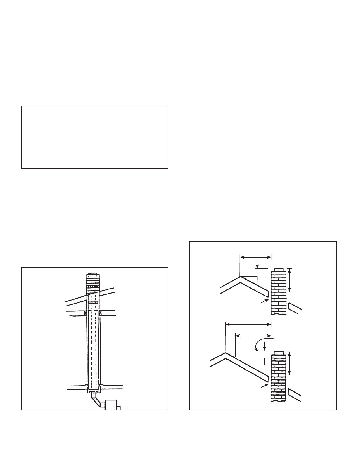
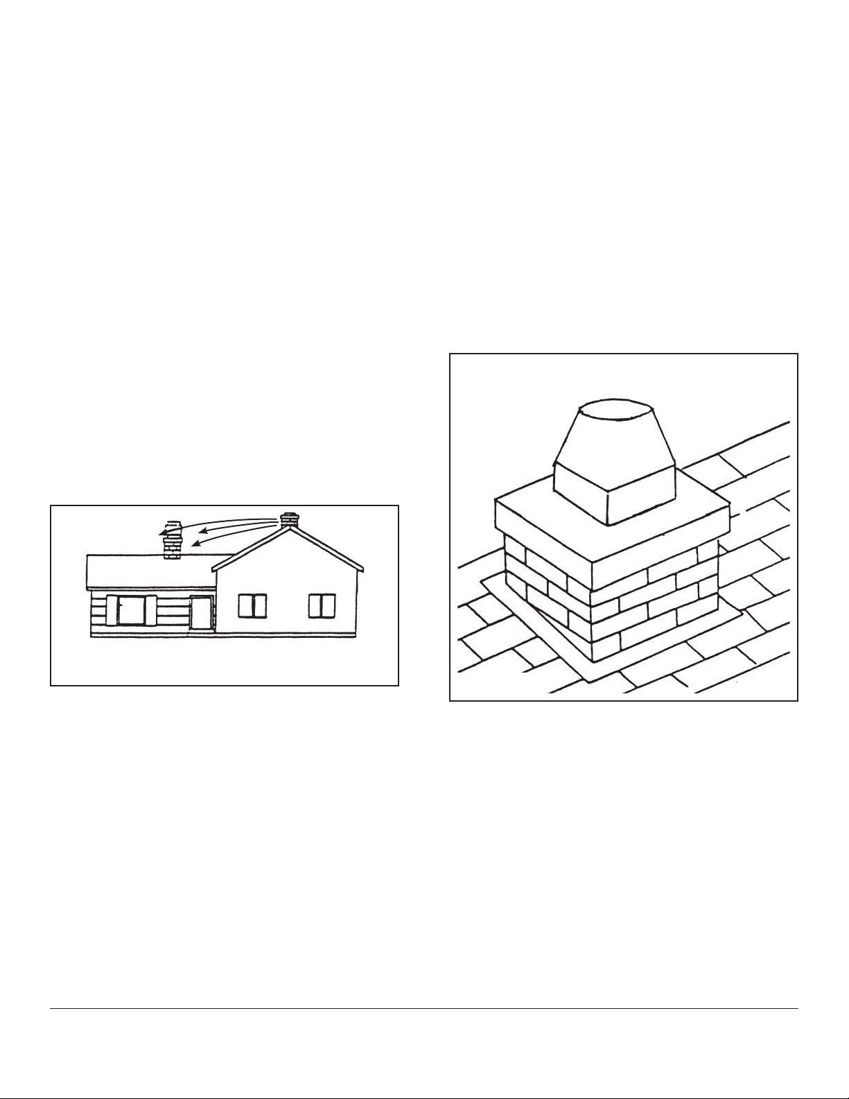
Chimney Requirement ....................................... 6” Class “A”
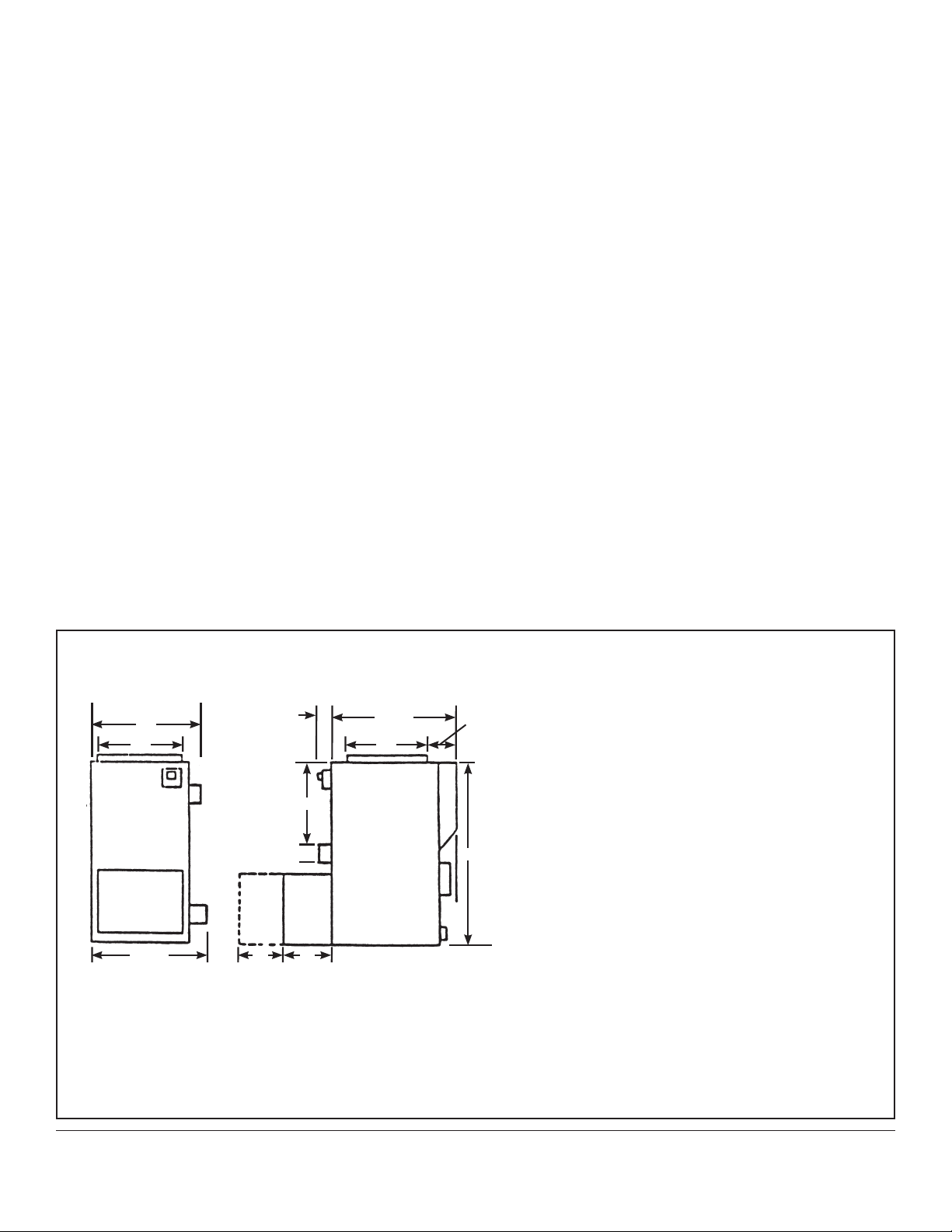
SPECIFICATIONS
Figure 1
27” 34.25”
24” 24”
30.75” 10” 18”
4.5”
2”
51.5”
6”
15.5”
Your Vapor-Fire Model 100 furnace is warranted for
(10) years against defects in materials and workman-
ship from the date of purchase, except for electrical
components and the blower, which carry a (1) year
manufacture warranty. Warranty does not apply to
re-bricks, seals, latches, hinges, or other moving
parts subject to normal wear and tear.
The manufacturer’s warranty extends only to the orig-
inal purchaser, applies to normal residential use, and
is not transferable.
The furnace must be installed, maintained, and op-
erated according to the Manufacturer’s Operator’s
Instructions. The warranty is voided if the Vapor-Fire
100 is used to burn materials not certied by the EPA
and not operated according to the owner’s instruc-
tions.
Upon obtaining authorization, returned products are
to be shipped prepaid to the manufacturer. Transpor-
tation fees to ship the product back to the purchaser
will be paid by the manufacturer.
This warranty applies to products purchased after
September 1st, 2021.

BOX 422 • TOWER, MN 55790 • USA • Tel (218) 753-2330 • www.lamppakuuma.com
4
1. Read thoroughly all of the installation and op-
eration instructions before attempting instal-
lation.
2. If your stove doesn’t have any bricks, install
the bricks as shown in gure 34 page 5 (also
see gure 19, page 12).
3. The unit must be set on a non-combustible
surface, such as brick, ceramic tile, stone, or
concrete and be at least 1 inch in thickness
and 18 inches larger than the dimensions of
the base as stated in the specications, g-
ure 1. The non-combustible oor protection
must extend at least 16 inches in front of
the unit.
4. Install the blower assembly to the back of the
unit as shown in gure 16. See gure 3 for
typical hot air hookup.
5. Use 6 inch stove pipe to connect the smoke
outlet in the back of the stove to AN AP-
PROVED CLASS A CHIMNEY. Install only
ONE connection to one ue. Make sure you
use at least three metal screws at each joint
connection, refer to gure 9.
6. Install a barometric draft control (eld con-
trol 6” RC/BT) as described and illustrated on
page 7 and 9, also see gures 9, 10 & 11.
7. WE SUGGEST THAT A LICENSED ELEC-
TRICIAN BE HIRED TO DO ALL YOUR
ELECTRICAL CONNECTIONS. See wiring
diagram, gure 23, page 14, also see gure
27 page 16.
1. Open re door.
2. Scrape the ashes through the grate.
3. Place a moderate amount of paper and kin-
dling on the FRONT half of the re chamber
oor.
4. Place your logs on top of the paper and kin-
dling, making sure that front face of the logs
are kept 1 inch away from the front inside
face of the re chamber, also make sure that
the primary air openings as shown in gure
18 are kept open. (page 12)
5. Ignite the paper.**
6. Open ash pan door approximately 1/4” until
automatic draft damper opens.
7. Momentarily hold the re door open, approx-
imately one-half inch, this will assist in ignit-
ing the kindling and helps to create the initial
draft.
8. Close the re door and ash pan door tight –
the electronic control automatically monitors
the re.
** Open ash pan door momentarily, when draft
control is activated – CLOSE ASH PAN
DOOR.
INSTALLATION INSTRUCTIONS
OPERATION GUIDELINES
STARTING A FIRE IN A COLD FIRE CHAMBER WITHOUT ANY HOT COALS

BOX 422 • TOWER, MN 55790 • USA • Tel (218) 753-2330 • www.lamppakuuma.com
5
Above Top of Plenum ........................................ 6”
From the Front .................................................. 48”
From Sides and Back ....................................... 6”
From Flue Pipe .................................................. 18”
From Back ......................................................... 10”
From Horizontal Warm Air Duct:
Within 3 feet of Plenum ..................................... 6”
Within 3 to 6 feet of Plenum ............................. 6”
Beyond 6 feet of Plenum .................................. 1”
Area between the furnace and combustible ducts
are insulated according to NFPA Bulletin 90B. This
copyrighted book is available from National Fire Pro-
tection Association, 60 Batterymarch Street, Boston,
Massachusetts 02110.
For equipment of this type, National Fire Protection Agency (NFPA) Standard No. 90B species the minimum
standard clearances to combustible surfaces as summarized below:
DUCT CLEARANCES FOR SOLID FUEL
DEVICES WITH BLOWER ASSEMBLY
Figure 2
3”
6”
6”
10”
MINIMUM
1”
6”
MINIMUM
FLOOR JOIST OR
COMBUSTIBLE
MATERIAL
HEAT SUPPLY
DUCTS
1” CLEARANCE TO
COMBUSTIBLES
BEYOND 6’ - 0”
SIDE VIEW
FURNACE
SUPPLY
AIR
PLENUM
CLEARANCE TO
COMBUSTIBLES
COLD AIR
RETURN
6” DIAMETER
FLUE PIPE
RECT.
DUCT
FLOOR TO BE
NON-COMBUSTIBLE MATERIAL
COMBUSTIBLE
WALLS
WARM AIR
DUCT
Figure 34
GRATE
U-BRICK
RETAINERS

CENTRAL FURNACE INSTALLATION
Figure 3
DUCTS SHOULD BE LARGE
ENOUGH TO HANDLE GRAVITY
AIR FLOW IN EVENT OF ELECTRIC
POWER OR FURNACE FAN FAILURE
(APPROXIMATELY 180-200 SQ. IN.)
WARM AIR DUCTS MUST BE
CONSTRUCTED ENTIRELY FROM
METAL DUE TO HIGH TEMPERATURES
WHEN OPERATED DURING ELECTRIC
POWER FAILURE.
BOX 422 • TOWER, MN 55790 • USA • Tel (218) 753-2330 • www.lamppakuuma.com
6
HOT
COLD
RETURN
H
O
T
H
O
T
C
O
L
D
CHECK
FLAP
STOP
STOP
TWO SPEED SWITCHES
500-1500 CFM ON DEMAND
CHECK FLAP
APPROX.
2’ X 2’ X 2’
OIL
OR
GAS
OR
ELECTRIC
180-200 SQ. IN. DUCT
VF
100
This is the just a basic
idea to tie the two systems
together. The cold air return
could be just an open
stairway or large floor grill. FOR POWER
OUTAGE
CHECK FLAPS
MUST ALLOW
FOR GRAVITY
FLOW.

CHIMNEY INFORMATION
The chimney is one of the most important yet most
neglected and misunderstood portions of any Sol-
id Fuel Burning Installation. THE FURNACE SHALL
NOT BE CONNECTED TO THE CHIMNEY WITH
OTHER HEATING DEVICES.
There are two types of Class “A” chimneys:
1. Masonry with tile liner suitable for venting resi-
dential or building heating appliances. (See NFPA
211.)
2. Class “A” Chimney, listed or certied by a na-
tionally recognized testing agency as suitable for
venting residential or building heating applianc-
es. If your masonry chimney has not been used
for some time, have it inspected by a qualied
person (building inspector, re department per-
sonnel, etc.). If a listed or certied manufactured
chimney is to be used, make certain it is installed
in accordance with the manufacturer’s instruc-
tions and all local and state codes. See Figure 5,
Manufactured Chimney Installation and Figure 6
of Masonry Chimney (note roof clearance) in ac-
cordance with NFPA 211.
COMMON CHIMNEY PROBLEMS
In order to have a proper operating Solid Fuel Heat
System, the chimney must be capable of providing
the draft required.
In the Vapor-Fire Model 100 Furnace, the required
draft is .03 to .06” water column (W.C.). This can be
measured using a draft gauge.
If the chimney cannot supply this constant draft, the
unit will not operate properly.
In all furnace installations using Vapor-Fire Model
100 furnaces, a barometric draft regulator must be
used and properly adjusted for proper draft. Provid-
ed – Set to .03 to .06 W.C. by sliding wt. to #3 to #6
vertical.
Figure 5 Figure 6
BOX 422 • TOWER, MN 55790 • USA • Tel (218) 753-2330 • www.lamppakuuma.com
7
CAUTION
THE CHIMNEY MUST BE A CLASS
“A” CHIMNEY IN GOOD OPERATING
CONDITION. DO NOT CONNECT THIS UNIT
TO A CHIMNEY FLUE SERVICING ANOTHER
APPLIANCE.
18”
2’
LESS THAN 18”
MORE THAN 18”
RIDGE 2” MINIMUM
2” MINIMUM
2” MINIMUM
CLASS A
CHIMNEY
3’ MINIMUM
CLASS AF
CHIMNEY
3’ MINIMUM
MINIMUM HEIGHT
REQUIRED ABOVE
ROOF SURFACE
WITHIN 16”
HORIZONTALLY
RIDGE

REASONS for insucient draft readings:
1. Leaky Chimney – Air leaking in around a loose
tting clean-out door, ue pipes not tight at the
joints, improper plug openings, or defective ma-
sonry.
2. Chimney Improper Height – Chimney does not
extend through the roof to a sucient height to
promote sucient draft or causes a down draft-
ing condition to take place. See NFPA 211.
3. Obstructions in the chimney – Check prior to us-
ing holding a mirror in chimney cleanout door.
This will give an inside view of the chimney.
4. Trees or other topographical barriers – Impending
the chimneys operation or causing a down draft
condition to exist. This can also be caused by ad-
jacent building or the roof of the same structure
where the chimney is not high enough (Figure 7).
5. Chimney Size – Chimney is not properly sized to
adequately t the appliance. It is either too small
or too large. Minimum chimney height – 14 foot.
Minimum Diameter – 6 inches.
6. Chimney Osets – Chimneys with osets should
not be used. They cause an obstruction to draft
as well as a place for debris to collect.
7. Elbow Restrictions – The ue pipe is connected
to the chimney with too many elbows reducing
the draft the chimney can provide. Use approxi-
mate 45 degree elbows.
8. Multiple Venting – When more than one (1) devise
vents into the same chimney ue.
When smoke rises into the chimney, it will rise in a
spiraling path.
The most important thing to remember about chim-
neys is their need for maintenance and cleaning. If
chimneys are not cleaned on a regular basis, it ef-
fects the draft, as well as make an attributing cause
to a chimney re.
The draft can be improved by using a chimney cone
(gure 8) or by extending the height of the chimney
and reducing the ue area. A cone or chimney exten-
sion can be made by a local sheet metal shop.
A properly operating chimney will tend to reduce the
amount of creosote that is left deposited.
Instructions for installation, draft measurement, ad-
justment of the barometric draft regulator.
BOX 422 • TOWER, MN 55790 • USA • Tel (218) 753-2330 • www.lamppakuuma.com
8
Figure 7
Figure 8
NOTE: THE CHIMNEY ON THE HOUSE ILLUSTRATED IS TOO LOW.
IT SHOULD BE RAISED TO COMPENSATE FOR DRAFTS.
GALVANIZED CHIMNEY CONE

BOX 422 • TOWER, MN 55790 • USA • Tel (218) 753-2330 • www.lamppakuuma.com
9
Figure 10
Figure 11
Figure 9
CAUTION
FOLLOW MANUFACTURER’S INSTRUCTIONS
ON HOW TO INSTALL THE BAROMETRIC
REGULATOR. MOUNT IT VERTICAL OR
VERTICALLY.
WARNING
LACK OF ENOUGH AIR FOR PROPER
COMBUSTION
If your house is fairly well insulated and relatively
air tight, it may be necessary for you to think of
providing an additional source of fresh air into
your house to eliminate the possibility of starving
the wood burning stove of the necessary amount
for good combustion.
If you have a clothes dryer, kitchen or a bathroom
exhaust fans, or even a replace burning and is
competing for the available combustion air which
could cause improper combustion. This could
result in some smoke backing up into your house.
You might need to look at installing an air to air
exchanger or nding another way to get some
fresh air to prevent the smoke back up.
For any questions feel free to call 1-800-358-
2049.
Use approximate 45 degree adj. elbows for angled
connections – NO HORIZONTAL PIPING.
INSTALLATION
Barometric Draft Control eld 6” RC/BT provided
with your model 100 Vapor Fire Furnace. A draft reg-
ulator is designed for insertion into a six (6) inch tee.
Refer to Figure 9 and 11 for mounting of the baro-
metric damper. It is recommended that the stove
pipe be installed with the crimped end down so that
if any creosote is formed, as a natural by-product of
combustion, it will run back towards the furnace and
not run through the joint to the outside of the smoke
pipe. The section of pipe (tee) holding the draft regu-
lator must be installed in either an angled or vertical
direction.
The draft control can be positioned within its collar
to an upright position.
It is essential that the draft regulator be located in
the same room (pressure zone) as the furnace and
as close as possible to the ue outlet.
After installation, make certain the draft control
barometric regulator is upright and level. Tighten
the screw to hold rmly in place. See Figure 10.
BAROMETRIC
DAMPER
VERTICAL
CONNECTION
ELBOW TO
FURNACE
METAL
SCREWS
45 DEGREE
CONNECTION
STOVE
CHIMNEY
BAROMETRIC
DAMPER

BOX 422 • TOWER, MN 55790 • USA • Tel (218) 753-2330 • www.lamppakuuma.com
10
Figure 12
Figure 13
Your Vapor-Fire Model 100 is shipped in two (2) sections. It may
be necessary to disassemble unit down to the main frame in
order to move into older homes without damage to the Model
100 shell or electronics. If this must be done please refer to the
following assembly steps and Figures 12-18.
BLOWER HOUSING
& FILTER BOX
FAN BASE
MAIN HOUSING UNIT
ANGLE IRON
WELDED
THERMO
COUPLE
LEFT
SIDE PANEL
RIGHT
SIDE PANEL
FRONT PANEL
TOP PANEL

ASSEMBLY IF UNIT IS NOT ASSEMBLED
Set main housing unit in place, refer to gure 12,
with metal screws provided, attach the right and left
panels to the bottom lip of the channel as shown.
Then place the top panel in place and secure it to
the top of the side panels with the metal screws. Se-
cure the front of the side panels with four screws to
brackets that are welded to both sides of the main
housing. Where the side panels overlap in the back
fasten the overlap with the metal screws. Install the
slip joint onto the back of the hood as shown. When
the hood is all assembled slide the felt, with the metal
slip joints into the square hole in the back.
ASSEMBLY OF THE BLOWER & FILTER
HOUSING BOX
Refer to gures 14 and 16, place fan assembly on the
fan housing base so that the holes in the brackets
align with the bolts that are already in the base. Place
the washers and nuts in place, but don’t tighten
down the nuts yet. Next, attach the side panels with
the metal screws that were provided. Then slide the
bottom channel in place so that the holes align with
the side panel holes and secure with metal screws
(the holes are on each end of the channel). Do the
same with the top channel and secure tightly.
Now slide the blower assembly housing towards the
back of the main housing so that the base slides un-
derneath the main housing, about 2-3 inches, mak-
ing sure that the side panels are against the main
housing hood and secure it with the metal screws.
Make sure that the fan outlet lip slides into the felt
lined square hole in the hood and forms a tight seal
around the lip. Now tighten the nuts. Set the large
cover in place so that the front lip slides into the slip
joint in the back of the hood.
Place the air lters into the channels. Place the lter
cover in place.
The completed assembly, without the fans, should
look like the drawing in Figure 15.
BOX 422 • TOWER, MN 55790 • USA • Tel (218) 753-2330 • www.lamppakuuma.com
11
Figure 15
Figure 14
Figure 16
BLOWER & FILTER BOX
BACK
PRE-ASSEMBLED
TOP
FAN HOUSING
BASE
UPPER
CHANNEL RIGHT
SIDE
LEFT
SIDE
BOTTOM
CHANNEL
24V RELAY
BLOWER FAN
OPENING
SMOKE COLLAR
FRONT HOOD
BONNET FLANGE
BOTTOM FAN
HOUSING
UPPER REAR
PANEL
FELT JOINT
ELECTRONIC
DRAFT
CONTROL
DRAFT
DAMPER
ASSEMBLY
CABLE CLIP
HIGH LIMIT
CONTROL
LOW LIMIT
CONTROL
MOTOR BOX
ASSEMBLY
FAN JUNCTION BOXBLOWER FAN BASE

Add front upper cover (refer to Figure 17). Cover lifts
up and slides into stove, when in, cover drops down
and is locked in place.
Fasten the draft control with gasket to the draft in-
take assembly (four screws). Note that it is critical to
keep this complete assembly airtight.
To tighten the door on the handle side – loosen the
two set screws, lower handle behind latch, push door
in tightly and tighten set screws. (Figure 18)
The re chamber (brick liner), grate, preheating intake
air chamber, primary and intermediate air distributor
is illustrated in gure 19, with the back removed.
Inspect grate to see that it is setting ush with the re
box oor.
Check vertical secondary air tubes to see if they are
in place. (Figure 19)
The two stainless steel removable secondary air
tubes are located on the right and left sides of the
door frame inside the re chamber. They actually pro-
vide the fourth level of combustion air to complete
the burn process. Under normal usage they won’t
burn out and need no maintenance (see Figure 19).
When adjusting doors, loosen the two screws (Figure
20) and push door in until there is a slight bind. As
you close the door, making sure it is not too tight,
tighten the screws.
BOX 422 • TOWER, MN 55790 • USA • Tel (218) 753-2330 • www.lamppakuuma.com
12
Figure 18
Figure 17
Figure 19
Figure 20
CLEAN OUT COVER
TEMPERATURE
HEAT SENSOR
FIRE DOOR
FRONT
BACK
PRIMARY AIR
OPENINGS
ASH DOOR
MOTORIZED ELECTRONIC
DRAFT CONTROL
DAMPER
ADAPTER BOX
DOOR
HANDLE
DOOR
LATCH
ADJUST SCREW
HINGE PIN
HINGE PIECE
DOOR FRAME
FIRE DOOR
PIVOT SCREW
ADJUSTMENT
SCREWS
SIDE PIECE
LATCH
ELECTRONIC
DRAFT CONTROL
GASKET
FRONT COVER
SECONDARY
AIR TUBES
THE LOGS BURN FROM THE
FRONT TO THE BACK.

BOX 422 • TOWER, MN 55790 • USA • Tel (218) 753-2330 • www.lamppakuuma.com
13
Figure 22
Install warm air plenum and cut hole for high limit
control. Refer to Figure 22.
Refer to wiring diagram Figure 23 and 25.
A. Mount control transformer.
B. Mount high limit control.
C. Mount low limit control.
D. Mount electronic control.
E. Connect thermocouple to terminals (white lead to
– red lead +).
F. Connect conduit from draft control box to fan
junction box with conduit nut and connect wires.
G. Run conduit from transformer to low limit switch
and fan junction box, Figure 26.
H. Add wires as shown in Figure 23 and connect.
I. Mount thermostat in house and connect to relay
control (24 VAC). Refer to Figure 23.
J. Connect wiring to fans in fan enclosure as shown
in Figure 23.
K. Run incoming conduit to transformer junction
box and connect to a separate circuit breaker
panel. Use a 15 amp AWG copper wire to the fur-
nace. Ground the furnace to the electrical system
ground.
L. We recommend that a licensed electrician do the
electrical wiring.
M. With wiring completed, check the system by
turning on the power. The light on the electronic
control should energize. The draft control will re-
main closed until the thermocouple is heated to
approximately 100-120 degrees F.
Figure 24 Figure 25
AIR SUPPLY
PLENUM
7/8” DIA. HOLE
HIGH LIMIT
CONTROL
LEVEL
THERMOSTAT WIRE
FRONT COVER
RIGHT SIDE
LEFT
SIDE
CONDUIT
TUBING
DRAFT
DAMPER
ASSEMBLY
ELECTRONIC
DRAFT
CONTROL
TRANSFORMER
SMOKE PIPE
HIGH LIMIT
CONTROL
LOW LIMIT CONTROL
DAMPER ADAPTOR BOX
FAN JUNCTION BOX
FAN HOUSING BASE
THERMOSTAT BASE
THERMOSTAT
6.25”
17.75”
7.5”

N. Install the cool air return plenum over the lters at
the rear of the furnace. See Figure 3.
O. Install the chimney smoke pipe along with the
barometric draft control furnished with the fur-
nace. See Figure 10.
P. To set draft for maximum setting. (.06 WC) Slide
WT to #6 Vertical.
BOX 422 • TOWER, MN 55790 • USA • Tel (218) 753-2330 • www.lamppakuuma.com
14
Figure 23
HIGH LIMIT
CONTROLLER 24 V ROOM THERMOSTAT
LOW VOLTAGE BY OTHERS
LOW
FAN
CONTROL
HIGH
LOW
RED
LOW
VOLTAGE
INCOMING POWER
115 VAC (15 AMP)
INSIDE COVER
JUNCTION BOX
4” X 4” X 2”
4” X 4” X 2”’ BOX
INDICATES WIRE NUT
DOTTED WIRING BY OTHERS
BLUE TO RED FOR LOW SPEED
RED TO BLACK FOR HIGH SPEED
2” X 4” X 2” BLACK
YELLOW
BLUE
RED
WHITE
WT
OUTSIDE COVER
WT BLACK
RED BR BLACK
BLACK WT
GR
H N
WG
O
R C
Y
WHITE
RED
THERMOCOUPLE
PLUG-IN
24V
24V
WHITE
RED
GREEN
T/C PROCESSOR
PANEL
MODEL
VAPOR FIRE 100/200
T/C STEP
DAMPER
MODEL
VAPOR FIRE 100/200
BL
320 Volt AC surge protector has been installed. One leg connects to the
blue/brown connection and the other to the white neutral connection
on the 115 volt side (inside cover) of the 24 volt relay. (This prevents
surges to the 24 volt electronic control when the blower switches from
high to low speed.)

BOX 422 • TOWER, MN 55790 • USA • Tel (218) 753-2330 • www.lamppakuuma.com
15
Figure 26
PLENUM HIGH LIMIT CONTROL
LOW LIMIT
CONTROL
FILTER
RACK
PROCESSOR
PANEL
TC
CLEANOUT COVER
FAN BOX
JUNCTION
BOX
MOTORIZED ELECTRONIC
DRAFT CONTROL
TRANSFORMER RELAY
COVER
MAIN FURNACE
FIRE DOOR
ASH DOOR
1. Use 24 ga. stove pipe and adjustable elbows.
2. Angle your stove pipes upward towards the
chimney smoke exit hole.
3. Install barometric damper provided. Set to .03 to
.06 WC.
4. Avoid using 90 degree pipe bends unless it’s
one 90 degree and then straight up.
5. Use sheet metal screw to attach all the pipes
with at least three screws evenly spaced around
the pipe and any joint.
6. Check and inspect pipes periodically for
corrosion or any other defects.
SAFETY SHOULD ALWAYS BE NUMBER ONE
INSTRUCTIONS ON CONNECTING THE 6” STOVE PIPE

BOX 422 • TOWER, MN 55790 • USA • Tel (218) 753-2330 • www.lamppakuuma.com
16
NORMAL AUTOMATIC OPERATION
When power is turned on the furnace is cold, the
draft will be closed. As the temperature in the re box
rises to approximately 100-120°F, the automatic draft
opens allowing combustion air to enter the re cham-
ber. As the temperature in the re chamber rises, the
automatic draft will begin its throttling process until
it is completely closed, allowing maximum furnace
idling. (When it reaches your desired setting low to
high.)
As the outer heat jacket temperature rises past 105°F.
The secondary fan (low speed) starts automatically
and continues to operate until the re burns down
and the heat exchanger cools to approximately 90°F.
This is adjustable.
The primary fan (high speed) will turn on automati-
cally provided the side jacket is at 105°F whenever
the remote room thermostat is calling for heat. The
fan will also turn on automatically if the plenum tem-
perature rises to the setting on the high limit switch
(set at approximately 220°F.) and will continue to op-
erate until the temperature of the plenum has cooled
down to approximately 100°F. The high limit is set at
approximately 250°F. and if this temperature is ever
obtained, the electronic control will be entirely de-en-
ergized and the automatic draft controller will close.
Conditions will remain in this state until plenum tem-
perature has cooled with large fan running allowing
the automatic high temperature cut-out switch to re-
set the controller.
If this condition ever occurs, check to see if the
damper from the plenum is closed or for any obstruc-
tions in the cool air return or in the air supply ducts
and registers.
The display screen is furnished on the electric control
to provide the following:
A. The letters “O” and “P” will blink on and o and
the beeper beeps intermittently when there is an
open circuit in the thermocouple. The automatic
draft will remain closed. Replace thermocouple.
B. The capital letter “C” will be on the display when
the re chamber is cold (70-100°F) and this indi-
cates that the automatic draft damper is closed.
To heat the re chamber, start the re with the ash
pan door open, as soon as the capital letter “C”
goes o CLOSE the ASH PAN door. The display
screen will now show the number “3”.
C. The electronic control has four dierent stages
and the numbers “1”, “2”, “3”, and small letter “c”
indicate how much air is entering the re chamber.
D. The small letter “c” will appear on the screen
when the temperature in the re chamber has
reached it’s optimum level. (Your low to high set-
ting.) Now the shutter is completely closed, the
stove is now on what we call the pilot burn and
will continue like this until the re chamber cools
down and then the control again takes over and
will adjust the shutter opening based on the re
chamber temperature.
E. When the temperature in the re chamber is too
high the letters “A” and “L” blink on and o and
the alarm beeper sounds continuously. If this
condition occurs, check the “TO DO” list located
on the control.
F. IF HI-TEMP ALARM GOES ON -
TURN CONTROL POWER SWITCH OFF
CHECK WHAT TO DO
Is door dealing? Adjust hinges and latches to ensure they
are tight
Is draft = .03” - .06”? Adjust Barometric draft to lower setting
Is draft shutter closing? Inspect draft shutter on motor box
Is wood too dry? Mix some wetter wood with dry wood
Are you reloading on Burn down excess coals before
too many hot coals? reloading
Figure 27
STAT
ELECTRONIC
CONTROL
FAN
LOW
105°
WHITE
ROGERS
3F05-1
115 VAC
24 V
220°
250°
R1
R1
R1
H
L

Figure 29
IMPORTANT
KEEP ASH DRAWER EMPTY. IF ASHES ARE PERMITTED
TO BUILD UP ABOVE THE GRATE, THE GRATES COULD
WARP AND EVENTUALLY BURN OUT.
DANGER
NEVER BURN MATERIALS OTHER THAN WOOD LOGS,
PREFERABLY SPLIT AND DRIED.
A CHIMNEY FIRE OR HEAT EXCHANGER FAILURE
COULD RESULT. THIS INCLUDES LARGE AMOUNTS
OF CORRUGATED BOXES, WOODSHAVINGS, PAPER
SCRAPS, DRIED CHRISTMAS TREES, COAL, GARBAGE,
TIRES OR OTHER BURNABLE PRODUCTS.
IMPORTANT
DURING NORMAL OPERATION, FIRING DOOR
AND ASH DOOR MUST BE KEPT TIGHTLY
CLOSED. AIR LEAKAGE WILL CAUSE LOSS OF
EFFICIENCY RESULTING IN HIGHER HEATING
COSTS. IF DOOR GASKETS BECOME WORN,
REPLACE WITH 5/8” AND 1/2” CERAMIC
ROPE AVAILABLE FROM LOCAL SOURCES.
BOX 422 • TOWER, MN 55790 • USA • Tel (218) 753-2330 • www.lamppakuuma.com
17
DOS AND DONT’S OF OPERATION
Wood Firing the Unit
Rake hot coals
to the FRONT as
shown, DO NOT
BLOCK PRIMARY
AIR OPENINGS.
Keep coals
approximately 1”
from front air inlets.
HOT COALS
ASHES
HOT
COALS
ASH PAN
RAKE
A
I
R
P
R
I
M
A
R
Y
Figure 30
Periodically remove ashes from the ash pan via the ash pan door
(see gures 17, 26, 29, and 30). Always dispose of ashes in a
metal container with a tight metal cover. Do not store ashes in-
side your house. Always store the metal ash container in a well
ventilated area or outdoors as ashes may contain live coals (em-
bers) which may emit carbon monoxide. Do not place the metal
ash container next to anything combustible. Pour some water in
the container, but do this outdoors in case of live embers. Stir
the ashes to distribute the water. Allow at least 3 days for water
to fully penetrate all ashes before bagging ashes and disposing
in the trash. Make sure you are complying with all local ordi-
nances relating to wood-ash disposal. Many local landll sites
have ash disposal containers.

BASIC FIRING INSTRUCTIONS
RULES TO FOLLOW
A. Use dry seasoned wood (15 to 30 percent mois-
ture content), soft wood cut and split in the spring
and dried over the summer under cover. Hard-
wood requires one year drying time – fall to fall.
B. Use a maximum of 22” wood lengths. 20” wood
works the best.
C. Never burn less than two (2) rows of wood (3 pc.
min.) in a triangle shaped pile.
D. Always preheat a cold stove before any wood
lengths are added by burning paper and kindling.
E. ALWAYS RAKE COALS FORWARD TO THE
FRONT BEFORE ADDING WOOD LENGTHS,
NEVER RAKE THEM ANY CLOSER THAN 1”
FROM THE FRONT AIR INLET HOUSING.
F. ALWAYS ADD WOOD LENGTHS LENGTHWISE
IN THE FIRE CHAMBER AND PLACE THEM IN
THE FIRE CHAMBER SO THAT THE FRONT
FACE OF THE WOOD IS APPROXIMATELY ONE
(1) INCH AWAY FROM THE AIR INLET HOUS-
ING. BOTTOM PIECES MUST MAKE CONTACT
WITH THE HOT COALS THAT WERE RAKED
FORWARD.
G. Keep the front approximately one-third (1/3) 9”
portion of the re chamber free of ash by scrap-
ing the ashes through the open front grate and
into the ash pan using rake provided.
H. With the re chamber cold, periodically empty
the ash pan via the ash pan door. Secure the door
tightly when nished.
STARTING A COLD FURNACE – NO HOT COALS
A. Open re door.
B. Scrape entire re chamber ashes through open
grate, into ash pan using side paddle on ash
scraper provided.
C. Preheat re chamber with generous cuts of paper
and kindling and light.
D. Close re door – allow to preheat 5-10 minutes.
E. Open re door.
F. Rake hot coals forward.
G. Add full lengths of wood (18-21” minimum of two
rows) 1 to 2 inches from front face air inlets; they
usually also contact the back wall.
H. Close re door tight – the re and heat will be
electronically controlled.
STARTING WITH WARM FURNACE
AND WITH HOT COALS
A. Open re door.
B. Scrape front approximately 9” (1/3) of re cham-
ber ashes through open grate. Scrape front cor-
ners, using side paddle. Ashes in the front are
usually grey and uy.
C. Rake hot coals forward.
D. Add wood lengths (minimum of two rows) so that
there is at least 1 to 2 inches of space between
front of log and front face of air inlet.
E. Close re door tight – re and heat is electroni-
cally controlled.
BOX 422 • TOWER, MN 55790 • USA • Tel (218) 753-2330 • www.lamppakuuma.com
18
CAUTION
YOU MUST CHECK YOUR CHIMNEY FLUE
PIPE CONNECTOR FREQUENTLY WHEN
FIRST STARTING TO BURN WOOD TO
DETERMINE THE AMOUNT OF CHIMNEY
MAINTENANCE (CLEANING) THAT WILL
BE REQUIRED. THIS, OF COURSE, IS ALSO
DEPENDENT ON WOOD TYPE, MOISTURE,
AND, IN GENERAL, HOW THE FURNACE IS
USED.

BOX 422 • TOWER, MN 55790 • USA • Tel (218) 753-2330 • www.lamppakuuma.com
19
CAUTION
ELECTRIC POWER FAILURE
– TO IMPROVE GRAVITY AIR FLOW REMOVE
AIR FILTERS.
– DO NOT TAMPER WITH WOOD PRIMARY
AIR CONTROL.
– OPEN ALL AIR REGISTERS AND REMOVE
ALL OBSTRUCTIONS NEAR THEM.
– KEEP CHILDREN AWAY FROM AIR
REGISTERS, OR BURNS COULD RESULT.
– PRIMARY AIR DAMPER WILL OPERATE
AUTOMATICALLY WHEN ELECTRIC
POWER IS RESTORED.
– REMOVE FRONT LIFT OFF HOOD FOR
MORE GRAVITY HEAT FLOW.
NOTE
IF FOR ANY REASON THERE SHOULD BE
AN ELECTRIC POWER FAILURE, EITHER
FROM HIGH LIMIT CUT-OFF OR ELECTRICAL
POWER OUTAGE, THE DAMPER WILL
AUTOMATICALLY CLOSE, PREVENTING
OVER-FIRE WITH NO BLOWER AND HEAT
EXCHANGER DAMAGE.
RUNNING FURNACE DURING
POWER FAILURE
If unit was in operation
during a power failure,
leave ash and fire doors
closed.
WOOD BURNING FACTS
BE AWARE OF CREOSOTE “BUILD-UP” WHEN
BURNING WOOD!
Wood burning equipment will give you trouble with
creosote deposits under certain conditions, unless
you are aware of these conditions and avoid them.
Creosote is a tarry liquid or solid resulting from the
distilling of wood during the combustion process. It
consists of a number of elements which condense
and bake layer upon layer in the chimney ue.
Highly combustible in its solid and semi-liquid state,
creosote is present in the gases given o by burning
wood. Creosote may build up a considerable thick-
ness on the interior surface of the chimney and ue
pipes, considerably reducing their cross-sectional
area.
Creosote condenses from the ue gases when the
stack temperature drops below 250 degrees F. The
amount of creosote deposited in the pipe and chim-
ney is dependent on the amount of moisture in the
ue gases, the temperature of the stack, and how
completely the combustible elements in the ue
gases have been burned in the combustion pro-
cess. Most problems with creosote are due to poor
chimneys with low draft and cold walls and to a
low rate of burning when heat is needed during the
spring and fall months.
Moisture in the ue gases may be controlled by us-
ing the driest wood possible, mixing small pieces
with a very full load, and never using only large
wood during mild weather when combustion is rela-
tively slow. Use seasoned rewood approximately
15% to 30% moisture content.
WARNING
SERIOUS FIRE MAY RESULT IF A SUFFICIENT
CREOSOTE “BUILD-UP” IS PERMITTED OVER
AN EXTENDED PERIOD OF TIME.

BEST WOOD FOR BURNING
Generally wood should be cut at least a year in ad-
vance and properly split at that time.
This wood should also be stored out of the weather, if
possible. If the wood is to remain outside, be sure to
cover the top of the wood piles with sheets of metal,
etc. This wood should be brought inside and stored
there for at least two (2) weeks before it is red to
obtain top performance.
Soft woods burn at a faster rate per cord than do
hard woods, and have less BTUs per cord.
Know what types of wood to burn. Wood is safe,
clean and economical fuel. Freshly felled wood is not
suitable fuel due to the moisture content of the wood.
Well-seasoned wood is best for the proper produc-
tion of heat. The following table will give you some
relative values of the heating content of some of (the
more readily available wood).
Equivalent
Type Weight BTU’s Per Value #2
Cord Cord Air Fuel Oil
Dried Wood Gallons
––––––––––––––––––––––––––––––––––––––––––––––
White Pine 1800# 17,000,000 120
Aspen 1900 17,500,000 125
Spruce 2100 18,000,000 130
Ash 2900 22,500,000 160
Tamarack 2500 24,000,000 170
Soft Maple 2500 24,000,000 170
Elm 2750 24,500,000 175
Yellow Birch 3000 26,000,000 185
Red Oak 3250 27,000,000 195
White Oak 3750 27,700,000 200
Hard Maple 3000 29,000,000 200
Hickory 3500 30,500,000 215
USEFUL FACTS
No. 2 Fuel Oil – 140,000 BTU/gallon
Natural Gas – 100,000 BTU/therm
Propane Gas – 93,300 BTU/gallon
Butane Gas – 100,671 BTU/gallon
Electricity – 3,413 BTU/kilowatt – hour
TROUBLESHOOTING
IMPORTANT: Your Vapor-Fire Furnace is a controlled
combustion solid fuel burning device that heats by
the pyrolysis of wood at a slow rate. If you load the
furnace and in a short period of time open the re
door, smoke will be expelled from the re door. This
is to be expected.
SMOKE PUFFS FROM VAPOR-FIRE FURNACE
A. Check the chimney draft. With a wood re burn-
ing, the chimney should supply .03” to .06” up-
draft.
B. Check automatic draft control for proper opera-
tion.
C. Check the smoke pipe and be sure it’s clean.
D. Chimney may be too low. Increase its height.
Make sure the chimney is structurally sound.
E. Add more air to the furnace room. Your home
may be so airtight, not enough oxygen is reach-
ing the re. Your heating contractor can do this.
Refer to Figure 31.
BOX 422 • TOWER, MN 55790 • USA • Tel (218) 753-2330 • www.lamppakuuma.com
20
Figure 31
FRESH AIR DUCT FOR
TIGHTLY SEALED HOUSE
4” PIPE
EMPTIES INTO
6” OUTER PIPE
DUCT
VF
100
FURNACE
4” FRESH AIR
DUCT
6” OUTER PIPE
This manual suits for next models
1
Table of contents
Popular Wood Stove manuals by other brands

J. A. Roby
J. A. Roby MAGNUM instruction manual

Dik Geurts
Dik Geurts Ivar 5-01, Low Instructions for installation

Drolet
Drolet Escape 1800 DB03102 Installation and operation manual

Osburn
Osburn MATRIX OB02022 Installation and operation manual

Schiedel
Schiedel SARGAS 1 Instructions for installation and operation

Intertek
Intertek Logwood 2469E owner's manual