LAN Power LP-2354 User manual

LP-2354
EXTERNAL 5 Port PoE Unmanaged 10/100Mbs Switch/Extender
(4 Ports Full PoE Power-up to 15.4 Watts per Port with 1 Uplink Port up to 100Mbs)
Installation Guide
Purpose of this Guide
This Guide provides information and procedures for the product installation and operation of the 5 Port PoE
Unmanaged 10/100Mbs Switch/Extender (LP-2354). This document is intended for technical personnel and
to use this document effectively, you should have a working knowledge of Local Area Networking (LAN)
concepts and hardware installation. In addition, you should be familiar with the following: Connection of
Patch Cables with RJ45 connectors and the LAN addressing map for your particular Network, Mounting of
Network hardware in a 19” equipment rack and local practices for power cord connections.
IMPORTANT SAFETY INSTRUCTIONS FROM LAN Power
Read and keep these instructions. Follow all instructions and heed all warnings. Although the IP67 Housing
is weather resistant rated – DO NOT submerge this equipment in water. Install in accordance with
manufacturer’s instructions. Unplug this equipment during lightning storms or when unused for long
periods of time. Refer all servicing to qualified service personnel. Servicing is required when the equipment
has been damaged in any way, liquid has been spilled, or object has fallen into the equipment, the internal
electronic equipment has been exposed to rain or moisture, does not operate normally, or has been dropped.
The AC mains outlet, or appliance coupler shall be readily available to the operator as a means of power
disconnection.
CAUTION – These servicing instructions are for use by qualified service personnel only. To reduce the risk of
electric shock, do not perform any servicing other than that contained in the operating instructions unless
you are qualified to do so.
If You need Help or additional support relating to the contents of this Guide, please contact LAN Power
using one of the following methods: Phone: 1-510-275-4572 Fax: 1-510-824-5654 Mail: LAN Power, 47835
Westinghouse Drive, Fremont, CA 94539 Web Address: www.lan-power.com Email: support@lan-power.com
Before contacting LAN Power for technical support, please have the following information ready: the
product model number and unit serial number, a description of the failure or symptoms of problem. A
description of any action(s) already taken to resolve the problem (e.g., changing ports, rebooting the unit,
etc...). The type of End device being powered including Manufacturer name and part number and powering
requirements of the IP End Device. A description of your Network environment (layout, Ethernet switch
description, cable type, etc...). The unit history (i.e., have you returned the unit before, is this problem a
recurring problem, etc...)
Please note only qualified personnel should install this unit and
read instructions before attempting to install this unit
Verifying Contents of Package - Unpack the PoE Injector and verify that you have the
following items: LP-2354 5 Port PoE Unmanaged 10/100Mbs Switch/Extender
NOTE: THE LP-2354 DOES NOT INCLUDE A POWER SUPPLY and MUST BE PURCHASED
SEPERATELY. Use either the LAN Power LP-2575 (Single Port ULTRA High Power Midspan
PoE Injector) or LP-2304PSU (AC Mains Power Supply Unit)
Technical Considerations -Before you mount the 5 Port PoE Unmanaged 10/100Mbs Switch/Extender
to a fixed location, consider all of the following: Determine optimal placement, check patch cord routing
and AC outlet location. Collect and document Network information as required. Ensure the CAT 5 (or
higher) cable length from the LP-2354 to the Powered End IP device does not exceed 328 feet/100 meters
total length.
Powering Up and Installing the 5 Port PoE Unmanaged 10/100Mbs Switch/Extender
1.) Remove the Back Mounting Plate from the IP67 External Housing which is done by removing the 4 screws
- (2 on left side and 2 on right side)
2.) Mount the Back Mounting Plate to desired location (Wall, Pole, etc.) – Mounting Fixing NOT INCLUDED
3.) Mount the IP67 Housing to the Back Mounting Plate with the 4 screws (2 on left side and 2 on right side)
4.) Bring all LAN Data Cables into the IP67 Enclosure via the 3 separate wiring glands provided. Please note
that the Right Wiring Gland has a single wire grommet and should be used for the powering of the LP-2354.
The incoming power is not supplied with the LP-2354 and the LP-2575 (Single Port ULTRA High Power
Midspan PoE Injector) or LP-2304PSU (AC Mains Power Supply Unit) must be used to power the LP-2354. The
Middle and Left Wiring Glands are supplied with a 2 (two) LAN Data Cable wiring gland and these should be
IEEE 802.3af
Compliant
used for the LAN Data Cables going out to the End IP Devices.
Once you have installed and secured your LAN Data Cables inside the IP67 Enclosure via the Wiring Glands:
5.) Connect the Power Supply Unit for the LP-2354 (which IS NOT SUPPLIED with unit and must be
purchased separately) The LP-2354 can be powered with one of the following units:
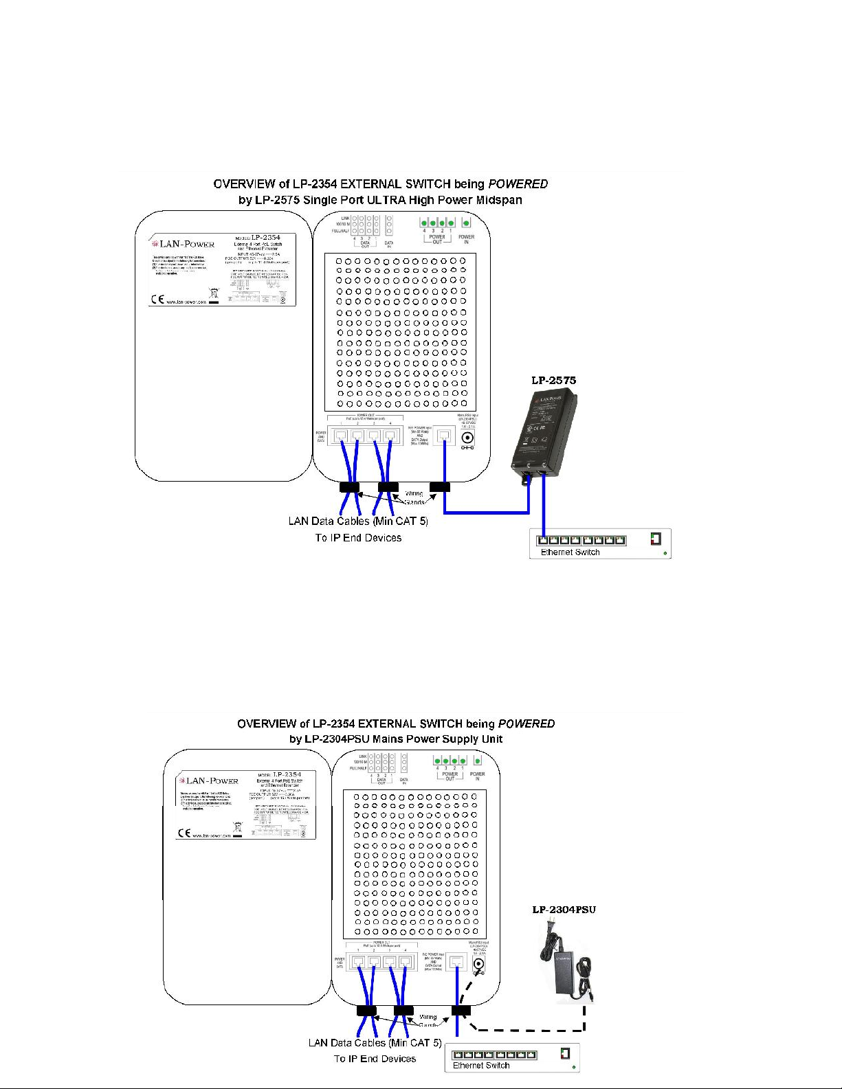
a.) Connecting a LAN Power LP-2575 (Single Port ULTRA High Power Midspan PoE Injector) – Connect
a LAN data cable - CAT 5 (or higher) from the RJ45 port labelled OUT (bottom left) of the LP-2575 and
the other end of the cable to the bottom right RJ45 port of the LP-2354 PCB. Once connected the
POWER IN LED (top right LED of the LP-2354 PCB) will illuminate solid green.
b.) Connecting a LAN Power LP-2304PSU (AC Mains Power Supply Unit) – Plug the LP-2304PSU into
an AC Outlet or UPS (Uninterruptible Power Supply Unit). Plug the DIN Plug Connector into the
bottom right DIN Connector Plug (round Power Input) of the LP-2354 (far right of LP-2354 PCB) Once
connected the POWER IN LED (top right LED of the LP-2354 PCB) will illuminate solid green. .)If
using a LAN Power LP-2304PSU to power the LP-2354 - Attach a LAN data cable – CAT 5 (or higher)
from the bottom far right RJ45 port (PoE Power Input and DATA OUT) of the LP-2354 PCB to
ETHERNET SWITCH or IP Monitoring Device such as a computer. Up to 100Mbs of data will be
transmitting from this cable which is generated from the IP End Devices.

6.) Attach separate LAN data cables – CAT 5 (or higher) from each of the 4 x RJ45 ports on the bottom left of
the LP-2354 PCB to each of the IP End Devices. Note: The maximum LAN data cable distance from LP-2354
to the IP End Device is 328 Feet/100 Meters. Once the IP End Device is connected properly the following
LED’s will identify the following:
DATA IN LED will illuminate.
PoE (15.4 Watts) POWER OUT 1 2 3 4 LED will illuminate if the IP End Device connected to the port
has been detected as PoE enabled Device to IEEE 802.3af standard and up to 15.4 Watts of PoE Power
is being supplied to the IP End Device.
DATA OUT-FULL/HALF LED will illuminate if the IP End Device is transmitting Full Duplex. If the
IP End Device is transmitting in Half Duplex the LED will not illuminate but DATA IN LED will be lit.
DATA OUT-10/100Mbs LED will illuminate if the LP-2354 detects the IP End Device is transmitting
up to 100Mbs. If the IP End Device is transmitting at 10Mbs or less the LED will not illuminate.
DATA OUT-LINK LED will Flash Yellow as the LP-2354 detects presence and transmission of any data
on the respective port.
The unit is now operating properly.
Note: The LP-2354 is enabled with DHCP and therefore requires no programming.
Two Year Limited Warranty
LAN Power warrants to the original consumer or purchaser that each of its products, and all components
thereof, will be free from defects in material and/or workmanship for a period of 2 years from the original
purchase date. Any warranty hereunder is extended only to the original consumer or purchaser and is not
assignable. More at www.lan-power.com
Notice to user
LAN Power reserves the right to make changes in specifications and other information contained in this
document and its web site without prior notice. The reader should in all cases consult LAN Power to determine
whether any such changes have been made. The hardware described in this document is subject to change
without notice due to market conditions or user requirements.
SAFETY APPROVAL:
47835 Westinghouse Drive
Fremont, Ca. 94539 USA
Telephone: +1-510-275-4572 FAX: +1-510-284-2420
www.lan-power.com [email protected]
External PoE Switch POWERED by PoE
Rev 12-12
Table of contents


