10
Water Meter
The totalizer keeps track of the gallons using a water meter. The water meter is a turbine style meter with a magnetic pickup that sends a pulse to
the electronics for every revolution of the meter turbine. The meter turbine is removable for inspection and cleaning. Make sure water is bypassed
or turned off when removing the meter for maintenance. The meter has a three pin plug that connects to the electronic board.
LEDs
Normal colors for the LEDs are green, yellow and red, which are dependent on the totalizer value.
• Green: 0–90% of the programmed totalizer maximum
• Yellow: 90–100% of the programmed totalizer maximum
• Red: Greater than 100% of the programmed totalizer maximum
If there is ow the LEDs should alternately turn off in the following pattern: 1-2-3-2 (repeat). The frequency that they turn off is linearly correspondent
to the ow rate being received from the water meter. For every 1 revolution from the meter, the LED pattern should be incremented to turn off the
next LED. If there are no pulse edges for 2 seconds, all the LEDs will turn on solid.
If the battery is determined to be low, the middle LED (#2) will turn blue. The battery is checked only once an hour to minimize the battery drain
from checking the voltage.
Pushbutton
The pushbutton allows for the totalizator to be reset as well as the maximum value to be programmed.
To reset the totalizator, the user should ip the umbrella cover over to see the logo/sticker. While looking at the top, the user should press and
hold the button on the electronics board for three seconds. When the totalizator is reset, the LEDs should ash green three times to conrm that
it is reset. “GREEN” colored LEDs (LED1) represent 100,000s and “BLUE” colored LEDs (LED2) represent 10,000s.
The push button allows the unit to be programmed for the total gallons limit. It can be programmed between the range of 10,000 gals.–990,000 gals.
To program the maximum value using the push button: press and hold the button while powering up the board (either battery power or 12VDC power).
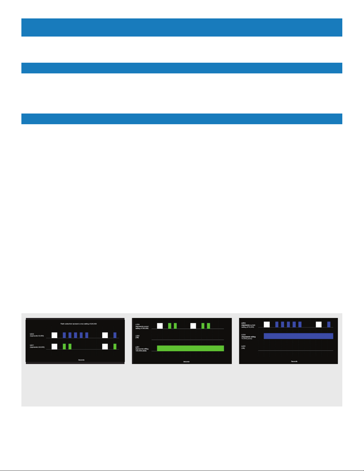
Once the board is powered LED 1 (right LED) will represent 100,000’s place and should be green. LED 2 (middle LED) will represent 10,000’s place
and should be blue. Both LEDs will be ashing at 1 Hz, the number of ashes that corresponds to the current setting for that digit placeholder. To
indicate the start of the ash sequence both LEDs should ash white for 1 second, then ash the appropriate number of times. Once both are done
wait 2 seconds and repeat. Refer to the gures below for an example.
FIGURE 1
To change the maximum gallons setting, press and hold
the button for 1 second. LED 1 should turn solid green, LED
2 should turn off and LED 3 should ash green the number
of times that corresponds to the current setting. Pressing
the button for less than 1 second would increment the value,
rolling over from 9 to 0. Figure 2 is an example of the LEDs
in this mode.
FIGURE 2
To save the setting for the 100,000s place and begin editing
the 10,000s place press and hold the button for greater than
1 second. LED 1 should turn off, LED 2 should turn solid
blue, and LED 3 should ash blue the number of times that
corresponds to the current setting. Again, pressing the button
for less than 1 second would increment the value, rolling over
from 9 to 0. Figure 3 is an example of the LEDs in this mode.
FIGURE 3
To save the setting for the 10,000s place, exit editing mode
and return to the mode in Figure 1 press and hold the button
for greater than 1 second. This will also save the current
setting into internal EEPROM memory.
The overall purpose of this device is to receive a water meter input and totalize the amount of water that passes through the meter. When there is
ow through the water meter, the lights ash at a rate that increases with the water ow rate. When the total amount of water owed reaches within
10% of a pre-selected amount the totalizer turns yellow. When the total amount reaches the pre-selected amount the totalizer turns red.
This unit is to be powered using +12VDC. The power input is a wire tail with a 2.5 mm center positive barrel jack.
The totalizer has a battery backup. The battery backup uses 3 AAA size batteries. The battery holder is a part of the PCB assembly and can be
accessed by removing the lid to the cartridge lter. Battery life will vary based on water ow when running on battery mode and type of batteries
used. With high continuous ow, the batteries are expected to last approximately less than 7 days. With no ow the batteries are expected to last
approximately 6 months.
POWER
OPERATION
WATER TOTALIZER NOTIFIER
Power Monitoring and Battery Mode
The board monitors the 12Vdc power and the battery power. If there is a power failure and no batteries are installed, the current totalizer value will
be saved to non-volatile memory. When power is resumed, the totalizer count will resume from when it had previously lost power.
The LEDs should shut off during battery mode. If the totalizer is to the yellow or red state or if the battery voltage gets low, the right LED will ash
on in the appropriate colors for 0.125 seconds every 30 seconds.