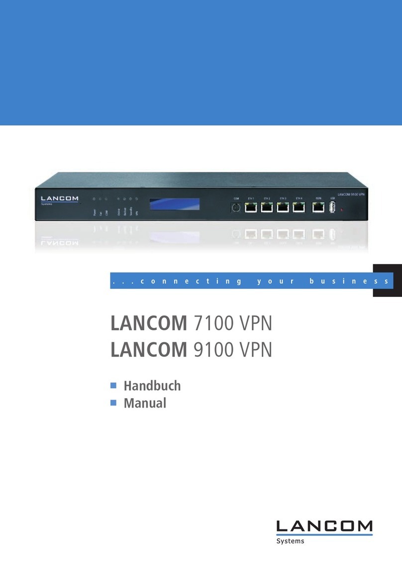
Lancom WLC-4006 User manual

110787/0110
LANCOM Systems GmbH
Adenauerstr. 20/B2
52146 Würselen
Germany
E-Mail: [email protected]
Internet www.lancom.eu
LANCOM WLC-4006
LANCOM WLC-4025+
LANCOM WLC-4100
LANCOM WLC-4025+ 쮿LANCOM WLC-4100
쮿Handbuch
쮿Manual
...connecting your business
110787_LC-WLC-MANUAL_cover.indd 1110787_LC-WLC-MANUAL_cover.indd 1 04.01.2010 05:56:4704.01.2010 05:56:47

LANCOM WLC-4006
LANCOM WLC-4025+
LANCOM WLC-4100

© 2010 LANCOM Systems GmbH, Wuerselen (Germany). All rights reserved.
While the information in this manual has been compiled with great care, it may not be deemed an assurance of product
characteristics. LANCOM Systems shall be liable only to the degree specified in the terms of sale and delivery.
The reproduction and distribution of the documentation and software supplied with this product and the use of its contents
is subject to written authorization from LANCOM Systems. We reserve the right to make any alterations that arise as the
result of technical development.
Windows®, Windows Vista™, Windows NT® and Microsoft® are registered trademarks of Microsoft, Corp.
The LANCOM Systems logo, LCOS and the name LANCOM are registered trademarks of LANCOM Systems GmbH. All other
names or descriptions used may be trademarks or registered trademarks of their owners.
Subject to change without notice. No liability for technical errors or omissions.
Products from LANCOM Systems include software developed by the OpenSSL Project for use in the OpenSSL Toolkit (http:/
/www.openssl.org/).
Products from LANCOM Systems include cryptographic software written by Eric Young ([email protected]).
Products from LANCOM Systems include software developed by the NetBSD Foundation, Inc. and its contributors.
Products from LANCOM Systems contain the LZMA SDK developed by Igor Pavlov.
LANCOM Systems GmbH
Adenauerstr. 20/B2
52146 Wuerselen
Germany
www.lancom.eu
Wuerselen, January 2010
11
0
7
8
7/
0
11
0

LANCOM WLC series
Preface
3
EN
Preface
Thank you for your confidence in us!
The WLAN Controllers LANCOM WLC-4006, LANCOM WLC-4025+ and
LANCOM WLC-4100 are state-of-the-art hardware components for medium-
and large-scale WLAN-installation management that is just as simple as it is
secure. All settings are entered just once into a central profile in the WLAN
Controller—the rest is pure and simple "Plug&Play". New Access Points are
found automatically. All of the configuration settings required for optimized
wireless network operations, such as the channel settings and security poli-
cies, are automatically transferred to all of the Access Points. Operations are
also monitored centrally (e.g. background scanning) by the WLAN Controller.
Greatly simplified WLAN management offers significant costs savings. WLAN
networks are extended easily and securely simply by "plugging in" new access
points. Even remote sites can be seamlessly integrated—any IP connection
will do. Smaller sites also benefit from the RADIUS/EAP server integrated into
the LANCOM WLAN Controller.
At the same time the LANCOM WLAN Controllers ensure maximum security as
all of the LANCOM Access Points in the network strictly observe corporate
security policies automatically. Potential security loopholes are eliminated by
permanent monitoring across all company sites.
Special highlights of the LANCOM WLAN Controller include, among others:
""Smart controller" for application-related or user-related WLAN net-
working
Reliability due to self-sufficient operations
No separate cabling necessary—any IP connection will do
"Split management" for LANCOM WLAN Routers
Automatic discovery and commissioning of access points and WLAN rout-
ers
Central administration of WLAN configuration profiles
Monitoring and assurance of encryption and QoS policy
Integrated RF optimization
Full support of VLAN, RADIUS and 802.x/EAP functions
Integrated router, firewall and VPN gateway
Scalable by adding Controllers; redundancy included

LANCOM WLC series
Preface
4
EN
Unparalleled operational reliability which prevents "single points of fail-
ure"
Security settings
To maximize the security available from your product, we recommend that you
undertake all of the security settings (e.g. firewall, encryption, access protec-
tion) that were not already activated when you purchased the product. The
LANconfig Wizard 'Security Settings' will help you with this task. Further infor-
mation is also available in the chapter 'Security settings'.
We would additionally like to ask you to refer to our Internet site
www.lancom.eu for the latest information about your product and technical
developments, and also to download our latest software versions.
Components of the documentation
The documentation of your device consists of the following parts:
Installation Guide
User manual
Reference manual
Menu Reference Guide
You are now reading the user manual. It contains all information you need to
put your device into operation. It also contains all of the important technical
specifications.
The Reference Manual is to be found as an Acrobat document (PDF file) at
www.lancom.eu/download or on the CD supplied. It is designed as a supple-
ment to the user manual and goes into detail on topics that apply to a variety
of models. These include, for example:
The system design of the operating system LCOS
Configuration
Management
Diagnosis
Security
Routing and WAN functions
Firewall
Quality of Service (QoS)
Virtual Private Networks (VPN)
Virtual Local Networks (VLAN)

LANCOM WLC series
Preface
5
EN
Wireless networks (WLAN)
Backup solutions
Further server services (DHCP, DNS, charge management)
The Menu Reference Guide (also available at www.lancom.eu/download or on
the CD supplied) describes all of the parameters in LCOS, the operating system
used by LANCOM products. This guide is an aid to users during the configu-
ration of devices by means of WEBconfig or the telnet console.
This documentation was created by …
... several members of our staff from a variety of departments in order to
ensure you the best possible support when using your LANCOM product.
Should you find any errors, or if you would like to suggest improvements,
please do not hesitate to send an e-mail directly to:
Our online services www.lancom.eu are available to you around the
clock if you have any questions on the content in this manual, or if you
require any further support. The area 'Support' will help you with
many answers to frequently asked questions (FAQs). Furthermore, the
knowledgebase offers you a large reserve of information. The latest
drivers, firmware, utilities and documentation are constantly available
for download.
In addition, LANCOM Support is available. For telephone numbers
and contact addresses for LANCOM Support, please refer to the
enclosed leaflet or the LANCOM Systems Web site.
Information symbols
Very important instructions. Failure to observe these may result in damage.
Important instruction that should be observed.
Additional information that may be helpful but is not essential.

LANCOM WLC series
Content
6
EN
Content
1 Centralized WLAN management 10
1.1 Introduction 10
1.2 Technical concepts 11
1.2.1 The CAPWAP standard 11
1.2.2 Smart controller technology 11
1.2.3 Communication between the Access Point and the WLAN
Controller 13
1.2.4 Zero-touch management 16
1.2.5 Split management 16
1.3 Just what can your LANCOM WLAN Controller do? 17
2 Installation 20
2.1 Package content 20
2.2 System requirements 20
2.2.1 Configuring the LANCOM devices 20
2.2.2 Operating access points in managed mode 21
2.3 Status displays and interfaces 21
2.3.1 Status displays 22
2.3.2 Device connectors 27
2.4 Hardware installation 29
2.5 Software installation 30
2.5.1 Starting the software setup 30
2.5.2 Which software should I install? 31
3 Basic configuration 32
3.1 Details you will need 32
3.1.1 TCP/IP settings 32
3.1.2 Configuration protection 34
3.2 Instructions for LANconfig 34
3.3 Instructions for WEBconfig 36
3.4 TCP/IP settings for Access Points 40
3.5 TCP/IP settings for PC workstations 40

LANCOM WLC series
Content
7
EN
4 Configuring the WLAN Controller 42
4.1 Basic configuration of the LANCOM WLAN Controller 42
4.1.1 Setting the time on the LANCOM WLAN Controller 42
4.1.2 Generating a default configuration 43
4.1.3 Assigning the default configuration to the new Access
Points 47
4.2 Extended settings 48
4.2.1 General settings 48
4.2.2 Profiles 50
4.2.3 Access point configuration 58
4.2.4 AP update 65
4.2.5 Stations 70
4.2.6 RADIUS server 73
4.2.7 Options for the WLAN Controller 74
4.2.8 Inheritance of parameters 76
4.3 Sample configurations 78
4.3.1 Accepting new Access Points into the WLAN infrastruc-
ture manually 78
4.3.2 Deactivating Access Points or permanently removing
them from the WLAN infrastructure 80
4.3.3 Backing up the certificates 82
4.3.4 Backing up and restoring further files from the SCEP-CA
85
4.3.5 LANCOM WLAN Controller backup 86
4.3.6 Load balancing between WLAN Controllers 89
4.3.7 Dynamic VLAN assignment 90
4.3.8 Virtualization and guess access via the LANCOM WLAN
Controller 93
4.3.9 Checking WLAN clients with RADIUS (MAC filter) 106
4.3.10 Internal and external RADIUS servers combined 107
4.4 Displays and commands in LANmonitor 111
4.5 Automatic RF optimization with LANCOM WLAN Controllers 113
4.6 Configuring the Access Points 115

LANCOM WLC series
Content
8
EN
5 Security settings 117
5.1 Security in the wireless LAN 117
5.1.1 Encrypted data transfer 117
5.1.2 802.1x / EAP 118
5.1.3 LANCOM Enhanced Passphrase Security 118
5.1.4 Access control by MAC address 119
5.1.5 IPSec over WLAN 119
5.2 Tips for the proper treatment of keys and passphrases 119
5.3 Security settings Wizard 120
5.3.1 LANconfig Wizard 120
5.3.2 WEBconfig Wizard 121
5.4 The security checklist 121
6 Setting up Internet access 126
6.1 The Internet Connection Wizard 126
6.1.1 Instructions for LANconfig 126
6.1.2 Instructions for WEBconfig 127
7 Connecting two networks 128
7.1 Which details are necessary? 128
7.1.1 General information 128
7.1.2 Settings for the TCP/IP router 130
7.1.3 Settings for NetBIOS routing 131
7.2 Instructions for LANconfig 131
7.3 1-Click-VPN for networks (site-to-site) 132
7.4 Instructions for WEBconfig 134
8 Providing dial-in access 135
8.1 Which details are necessary? 135
8.1.1 General information 135
8.1.2 Settings for TCP/IP 136
8.1.3 Settings for NetBIOS routing 136
8.2 Settings on the dial-in computer 137
8.3 Instructions for LANconfig 137
8.4 1-Click-VPN for LANCOM Advanced VPN Client 138
8.5 Instructions for WEBconfig 139

LANCOM WLC series
Content
9
EN
9 Appendix 140
9.1 Performance and characteristics 140
9.2 Connector wiring 141
9.2.1 Ethernet interface 10/100/1000Base-TX, DSL interface
141
9.2.2 Configuration interface (outband) 141
9.3 CE-declarations of conformity 142
10 Index 143

LANCOM WLC series
Chapter 1: Centralized WLAN management
10
EN
1 Centralized WLAN management
1.1 Introduction
The widespread use of wireless Access Points and wireless routers provides
great convenience and flexibility in network access for businesses, universities
and other organizations.
Yet in spite of the numerous advantages WLAN infrastructures offer, there are
still a number of unsettled issues:
All wireless Access Points must be configured and require appropriate
monitoring in order to recognize unwelcome WLAN clients, etc. The
administration of the Access Points, especially for larger WLAN infrastruc-
tures with the appropriate security mechanisms, requires advanced qual-
ifications and experience on the part of those responsible, and it ties up
considerable resources in the IT departments.
The manual customization of the configurations in the Access Points when
changes are made to the WLAN infrastructure can be time-consuming,
with the result that different configurations can be present in the WLAN
at the same time. Possibly some Access Points are missed during the
update procedure, which will result in inconsistent configurations.
Combined utilization of the shared communications medium (air) requires
effective coordination of the Access Points to avoid frequency interference
and optimize network performance.
In public places, Access Points are a potential security risk because the
devices themselves, including the security-related data in them such as
passwords, etc., are susceptible to theft. In addition, rogue Access Points
may be able to connect to the LAN unnoticed, bypassing the security pol-
icies that are in place.
Centralized WLAN management is the solution to these problems. The config-
uration of the Access Point is then no longer carried out in the devices them-
selves but by a central authority instead, the WLAN Controller. The WLAN
Controller authenticates the Access Points and transmits the correct configu-
ration to the approved devices. This allows for convenient configuration of the
WLAN from a central point and the changes to the configuration affect all of
the Access Points simultaneously. Optionally the configuration provided by the
WLAN Controller is not stored in the Access Point's flash memory but in RAM,
so security-related data cannot fall into the hands of unauthorized persons in
the event that devices are stolen. Only in "standalone" operation is the con-

LANCOM WLC series
Chapter 1: Centralized WLAN management
11
EN
figuration optionally saved for a defined period to flash memory (in an area
that cannot be read out with LANconfig or other tools).
1.2 Technical concepts
1.2.1 The CAPWAP standard
The CAPWAP protocol (Control And Provisioning of Wireless Access Points)
was adopted by the IETF (Internet Engineering Task Force) in March 2009 as
a standard for the centralized management of large WLAN infrastructures.
CAPWAP uses two channels for data transfer:
Control channel, encrypted with DTLS. This channel is used to exchange
administration information between the WLAN Controller and the Access
Point.
Datagram Transport Layer Security (DTLS) is an encryption protocol
based on TLS but, in contrast to TLS itself, it can be used for transfers
over connectionless, unsecured transport protocols such as UDP. DTLS
therefore combines the advantages of the high security provided by
TLS with the fast transfer via UDP. This also makes DTLS suitable for
the transfer of VoIP packets (unlike TLS) because, even after the loss
of a packet, the subsequent packets can be authenticated again.
Data channel, optionally also encrypted with DTLS. The payload data from
the WLAN is transferred through this channel from the Access Point via
the WLAN Controller into the LAN—encapsulated in the CAPWAP proto-
col.
1.2.2 Smart controller technology
In a decentralized WLAN structure with stand-alone Access Points (operating
as so-called "rich access points") all functions for data transfer take place in
the PHY layer, the control functions in the MAC layer, and the management
functions are integrated in the Access Points. Centralized WLAN management
divides these tasks among two different devices:
The central WLAN Controller assumes the administration tasks.
The decentralized Access Points handle the data transfer at the PHY layer
and the MAC functions.

LANCOM WLC series
Chapter 1: Centralized WLAN management
12
EN
A RADIUS or EAP server can be added as a third component for authenti-
cation of WLAN clients (which can also be the case in stand-alone
WLANs).
CAPWAP describes different scenarios for the relocation of WLAN functions to
the central WLAN Controller.
Smart Controller Technology from LANCOM Systems uses the local MAC pro-
cedure. This method provides for complete management and monitoring of
the WLAN data traffic directly in the Access Points. The only information
exchanged between the Access Point and the WLAN Controller is for network
management and ensures that the Access Points have a uniform configura-
tion.
Thanks to the reduction of centralized tasks, these WLAN infrastructures offer
optimum scalability. At the same time, infrastructure of this type prevents the
WLAN Controller, which has to process large portions of the overall data traf-
fic, from becoming a central bottleneck. In remote MAC and split MAC archi-
tectures, all payload data is forced to run centrally via the WLAN Controller.
However, in local MAC architectures data can alternatively be directly released
from the Access Points into the LAN, so providing high-performance data
transfer. This makes WLAN Controllers from LANCOM suitable for WLANs
adhering to the IEEE 802.11n standard, so offering significantly higher band-
widths than conventional WLANs. With break-out into the LAN, data can also
be directly routed into special VLANs. This makes it very easy to set up closed
networks, such as for guest access accounts.
ACCESS POINT
Management
Authentication
Realtime MAC
Non-realtime MAC
PHY layer
antenna
WLAN CONTROLLER
ACCESS POINT
Management
Authentication
Realtime MAC
Non-realtime MAC
PHY layer
antenna

LANCOM WLC series
Chapter 1: Centralized WLAN management
13
EN
1.2.3 Communication between the Access Point and the WLAN
Controller
As of firmware version LCOS 7.20 there is a difference between
LANCOM Access Points (such as the LANCOM L-54ag) and LANCOM
Wireless Routers (such as the LANCOM 1811n Wireless) with regard
to the ex-factory standard settings in the WLAN modules. In the fol-
lowing specifications, the general term Access Point will be used for
the most part.
Fôr a sucessful starting up the Access Points must comply with the following
requirements:
The Access Point has an IP address (static or assigned via DHCP)
The Access Point can reach a WLAN Controller in the LAN via broadcast
Alternatively: The Access Point can resolve the address on a WLAN
Controllers in the WAN using a DNS server (the “WLC-Address” is resolved
using “.company.intern”).
For a WLAN Controller in the WAN the firewall allows the communication
for DNS, CAPWAP at UDP Port 1027 and HTTP for SCEP.
Communication between an Access Point and the WLAN Controller is always
initiated by the Access Point. In the following cases, the devices search for a
WLAN Controller that can assign a configuration to them:
A LANCOM Access Point has the factory settings and is not yet configured.
In these settings the WLAN modules are deactivated; the Access Point
searches for a WLAN Controller in the LAN.
CAPWAP tunneling and layer-3 roaming
From one of the later LCOS versions, LANCOM WLAN Controllers also support transfer of the
payload data through a CAPWAP tunnel.
This allows selected applications such as VoIP to be routed via the central WLAN Controller,
for example. If WLAN clients change to a different radio cell, the underlying IP connection
will not be interrupted because it continues to be managed by the central WLAN Controller
(layer-3 roaming). In this way, mobile SIP telephones can easily roam even during a call—
between Ethernet subnets.
Managing data streams centrally can also make configuring VLANs at the switch ports
unnecessary in environments with numerous VLANs because all CAPWAP tunnels are cen-
trally managed on the WLAN Controller.

LANCOM WLC series
Chapter 1: Centralized WLAN management
14
EN
A LANCOM Access Point is already configured; at least one WLAN module
is manually set to operate as 'managed' ('Configuring the access points').
The Access Point searches for a WLAN Controller in the network on behalf
of the one or more corresponding WLAN modules.
A LANCOM Wireless Router is already configured; at least one WLAN
module is manually set to operate as 'managed'. The wireless router
searches for a WLAN Controller in the network on behalf of the one or
more corresponding WLAN modules.
At the beginning of communications, the Access Point sends a "Discovery
Request Message" to find any available WLAN Controllers. This request is sent
as a broadcast. However, because in some structures a potential WLAN
Controller cannot be reached by a broadcast, special addresses from addi-
tional WLAN Controllers can also be entered into the configuration of the
Access Points.
DNS names of WLAN Controllers can also be resolved. All Access Points with
LCOS 7.22 or higher have the default name 'WLC-Address' pre-configured so
that a DNS server can resolve this name to a LANCOM WLAN Controller. The
same applies to the DNS suffixes learned via DHCP. In this way, a DNS server
can automatically suffix the controller's standard name to 'WLC-address.com-
pany.internal'. This also makes it possible to reach WLAN Controllers that are
not located in the same network, without having to configure the Access
Points.
Please note that the access points must have an IP address in order to com-
municate with the WLAN Controller. The IP address can either be entered into
the access point as a fixed value, or retrieved from a DHCP server.
If the access point is to retreive an IP address from a DHCP server but
the server is unobtainable, then an access point which is restarting
may not have an IP address, und thus be unable to communicate with
the WLAN Controller.
From the available WLAN Controllers, the Access Point selects the best one
and queries it for the structure of the DTLS connection. The "best" WLAN
Controller for the Access Point is the one with the least load, i.e., the lowest
ratio of managedAccess Points compared to the maximum possible Access
Points. In case of two or more equally "good" WLAN Controllers, the Access
Point selects the nearest one in the network, i.e., the one with the fastest
response time.

LANCOM WLC series
Chapter 1: Centralized WLAN management
15
EN
The Access Point is provided with the configuration for the integrated SCEP
client via the secure DTLS connection – the Access Point is then able to retrieve
its certificate from the SCEP CA via SCEP. Once this is done, the assigned con-
figuration is transferred to the Access Point.
SCEP stands for Simple Certificate Enrollment Protocol; CA for Certifi-
cation Authority.
The WLAN Controller then uses an internal random number to determine a
unique and secure session key which it uses to protect the connection to the
Access Point. The CA in the WLAN Controller issues a certificate to the Access
Point by means of SCEP. The certificate's relationship is protected by a one-
time-only "challenge" (password). The Access Point uses this certificate for
authentication at the WLAN Controller to collect the certificate.
Authentication and configuration can both be carried out either automatically
or only with a corresponding entry of the Access Point's MAC address in the
AP table of the WLAN Controller. If the Access Point's WLAN modules were
deactivated at the beginning of the DTLS communication, these will be acti-
vated after successful transfer of the certificate and configuration (provided
they are not explicitly deactivated in the configuration).
The management and configuration data will then be transferred via the CAP-
WAP tunnel. The payload data from the WLAN client is then released in the
Access Point directly into the LAN and transferred, for example, to the server.
WLAN CONTROLLER
ACCESS POINT
DTLS request
SCEP configuration
SCEP request
Certificate
Configuration

LANCOM WLC series
Chapter 1: Centralized WLAN management
16
EN
1.2.4 Zero-touch management
With their ability to automatically assign a certificate and configurations to
the requesting Access Points, LANCOM WLAN Controllers implement true
"zero-touch management". Simply connect new Access Points to the LAN—
no further configuration is necessary. This simplification to only having to
install devices reduces the workload for IT departments, especially in decen-
tralized structures, because no special IT or WLAN expertise is required for the
setup at the remote locations.
1.2.5 Split management
LANCOM Access Points can locate your WLAN Controller in remote net-
works—a simple IP connection, such as via a VPN path, is all that you need.
As the WLAN Controllers only influence the WLAN part of the configuration in
the Access Point, all other functions can be managed separately. This division
of the configuration tasks makes LANCOM WLAN Controllers perfect for
establishing a company-wide WLAN infrastructure that is based at the head-
quarters and includes all of the branch and home offices connected to it.
ACCESS POINT
WLAN CONTROLLER
LAPTOP/W-LAN
SERVER
Payload data
Payload data
Management and configuration
CAPWAP tunnel
CAPWAP tunnel for payload data*
* Not
y
et available with earl
y
shipments

LANCOM WLC series
Chapter 1: Centralized WLAN management
17
EN
1.3 Just what can your LANCOM WLAN Controller do?
The following table provides a comparison of the properties and functions of
your device depending on the model.
LANCOM
WLC-
4006
LANCOM
WLC-
4025+
LANCOM
WLC-
4100
WLAN controlling
Number of managed devices (factory setting / upgrade optional to maxi-
mum number)
6 / 12 25 / 100 100 / 1000
Automatic detection of WLAN controllers by the LANCOM Access Points or
WLAN routers
✔✔✔
Automatic or manual authentication of the Access Points ✔✔✔
Communication between controller and Access Pointsvia simple IP con-
nection with CAPWAP
✔✔✔
Encryption of the control data with DTLS, including HW crypto accelerator ✔✔✔
Inheritance of configuration profiles, also multi-level ✔✔✔
Self-sufficient operations for continued operation even when the connec-
tion to the WLAN Controller is interrupted
✔✔✔
Advanced routing and forwarding (ARF) with customized DHCP, DNS,
routing, firewall and VPN functions for these networks, assignment of the
networks to SSIDs in the WLAN profile via VLAN IDs.
16 net-
works
16 net-
works
64 net-
works
Dynamic VLAN assignment for target user groups based on MAC
addresses, BSSID or SSID by means of an external RADIUS server.
✔✔✔
Integrated RADIUS server for MAC address list management ✔✔✔
Integrated EAP server for authentication of 802.1x clients using EAP-TLS,
EAP-TTLS, PEAP, MSCHAP or MSCHAPv2.
✔✔✔
Proxy mode for external RADIUS/EAP servers (forwarding and realm han-
dling)
✔✔✔
802.11e / WME: Automatic VLAN tagging (802.1p) in the Access Points.
Conversion to DiffServ attributes in the WLAN controller, provided it is
used as a layer-3 router
✔✔✔
Fast roaming via PMK caching and pre-authentication ✔✔✔
Further applications
Internet access ✔✔✔
LAN-LAN connectivity over VPN ✔✔✔

LANCOM WLC series
Chapter 1: Centralized WLAN management
18
EN
RAS server (over VPN) ✔✔✔
IP router ✔✔✔
DHCP and DNS server (separate for all ARF networks) ✔✔✔
N:N mapping for routing networks with the same IP-address ranges over
VPN
✔✔✔
LAN port can be configured to be a WAN port ✔✔✔
Policy-based routing ✔✔✔
NAT Traversal (NAT-T) ✔✔✔
PPPoE servers ✔✔✔
Layer 2 QoS tagging ✔✔✔
Spanning Tree Protocol ✔✔✔
802.1p ✔✔✔
LAN connection
Uplink interface for connection to the LAN.
Alternatively switchable as a LAN interface or as a WAN interface for con-
necting an SDSL modem.
1
Individual Gigabit Ethernet LAN ports, auto-crossover, individually switch-
able, for example as LAN or DMZ ports. Alternatively switchable as a WAN
interface for connecting an external DSL modem/router.
444
USB connector
USB 2.0 host port (high speed: 480 Mbps) for connecting a USB printer
and for future extensions
✔✔✔
Security functions
5 integrated VPN tunnels for secure network connections ✔✔✔
DTLS and IPsec encryption via hardware ✔✔✔
IP masquerading (NAT, PAT) to conceal individual LAN workstations
behind a single public IP address.
✔✔✔
Stateful-inspection firewall ✔✔✔
Firewall filter for blocking individual IP addresses, protocols and ports ✔✔✔
LANCOM
WLC-
4006
LANCOM
WLC-
4025+
LANCOM
WLC-
4100

LANCOM WLC series
Chapter 1: Centralized WLAN management
19
EN
Protection of the configuration from brute-force attacks. ✔✔✔
Configuration
Configuration with LANconfig or via web browser; additional terminal
mode for Telnet or equivalent terminal programs; SNMP interface and
TFTP server function.
✔✔✔
Serial configuration interface ✔✔✔
FirmSafe for no-risk firmware updates ✔✔✔
Optional software extensions
LANCOM WLC-PSPOT Option for guest-access accounts and
chargeable WLAN access to the managed access points
integrated ✔✔
LANCOM 2-Year Warranty Extension ✔✔✔
LANCOM Next Business Day Service Extension ✔✔✔
LANCOM
WLC-
4006
LANCOM
WLC-
4025+
LANCOM
WLC-
4100
Other manuals for WLC-4006
1
This manual suits for next models
2
Table of contents
Other Lancom Network Hardware manuals
Popular Network Hardware manuals by other brands

Dell
Dell VxRail P670F Installation and service manual

INSIGHT
INSIGHT DLP SENSOR 300 Hardware installation guide

Nexcom
Nexcom NSA 7146 user manual

Matrix Switch Corporation
Matrix Switch Corporation MSC-HD84AAL product manual

BlueNet Video
BlueNet Video BB01 instruction manual

CheckMK
CheckMK Rail2 Mark I manual

HP
HP X1600 - StorageWorks Network Storage System 5.4TB SAS Model NAS... user guide

TechnoSpark Systems
TechnoSpark Systems NMEA 2000 Wifi Replicator user manual

ADTRAN
ADTRAN NetVanta 8044M Specifications

Nexcom
Nexcom FTA 5180 Series user manual

Cocoon
Cocoon HE190087 instruction manual

Enttec
Enttec Storm 8 Quick start manual