manuals.online logo
Brands
  1. Home
  2. •
  3. Brands
  4. •
  5. Landoll
  6. •
  7. Industrial Equipment
  8. •
  9. Landoll 855 FINISHOLL Series User manual

Landoll 855 FINISHOLL Series User manual

F-718-0313 03/2013
LANDOLL CORPORATION
1900 North Street
Marysville, Kansas 66508
(785) 562-5381
800-428-5655 ~ WWW.LANDOLL.COM
Model 855 Boeing
Supplement
Operator’s Manual
All manuals and user guides at all-guides.com
F-718-0313 Edition i
Table of Contents
1 Operating Instructions
Front 6-1/2’ Ramp Assembly . . . . . . . . . . . . . . . . . . . . . . . . . . . . . . . . . . . . . . . . . . . . . . . . . . . . . 1-1
Support Boom Assembly . . . . . . . . . . . . . . . . . . . . . . . . . . . . . . . . . . . . . . . . . . . . . . . . . . . . . . . 1-3
Lowering Support Boom Assembly . . . . . . . . . . . . . . . . . . . . . . . . . . . . . . . . . . . . . . . . . . . . 1-3
Raising Support Boom Assembly . . . . . . . . . . . . . . . . . . . . . . . . . . . . . . . . . . . . . . . . . . . . . 1-3
All manuals and user guides at all-guides.com
ii F-718-0313 Edition
All manuals and user guides at all-guides.com
1-1
Chapter 1
Operating Instructions
Figure 1-1: Ramp Terminology
Front 6-1/2’ Ramp Assembly
1. Remove gooseneck from trailer per instructions in
operator’s manual.
2. Unhook safety latches holding ramps to trailer frame
(See Figure 1-1.)
3. Remove wired remote from frame slot on driver’s side
of trailer.
4. Make sure area where ramps are to land are free
from all obstacles and personnel.

CAUTION
5. Operate remote by pushing switch to “DOWN”
position.
6. To raise the ramps push switch to “UP” position.
7. Engage locks to secure ramps.
8. Return remote to storage location.
WIRED REMOTE
CONTROL
LOCATION
RAMP LATCH (IN
UNLOCKED POSITION)
6 DEGREE
RAMP WELDMENT
RAMP LATCH (IN
LOCKED
POSITION)
ramp terms
Before folding or unfolding ramp(s), confirm that
harness and air hoses used to connect to gooseneck
do not interfere with cylinder movement.
All manuals and user guides at all-guides.com
1-2 F-718-0313 Edition
OPERATING INSTRUCTIONS
Figure 1-2: Support Boom Terminology
support boom terms
SUPPORT BOOM
ASSEMBLY
ATTACH SLING TO
THIS CROSSMEMBER
FOR RAISING OR
LOWERING
3/4-10 x 5-1/2 HEX
HEAD CAP SCREW AND
HEX LOCK NUT
3/4-10 X 6 HEX HEAD CAP
SCREW AND HEX LOCK
NUT
3/4-10 X 6 HEX HEAD CAP
SCREW, PLATFORM
WASHER, AND HEX LOCK
NUT
3/4-10 x 5-1/2 HEX
HEAD CAP SCREW AND
HEX LOCK NUT
PLATFORM BRACE
A
B
C
D
E
E
All manuals and user guides at all-guides.com
OPERATING INSTRUCTIONS
1-3
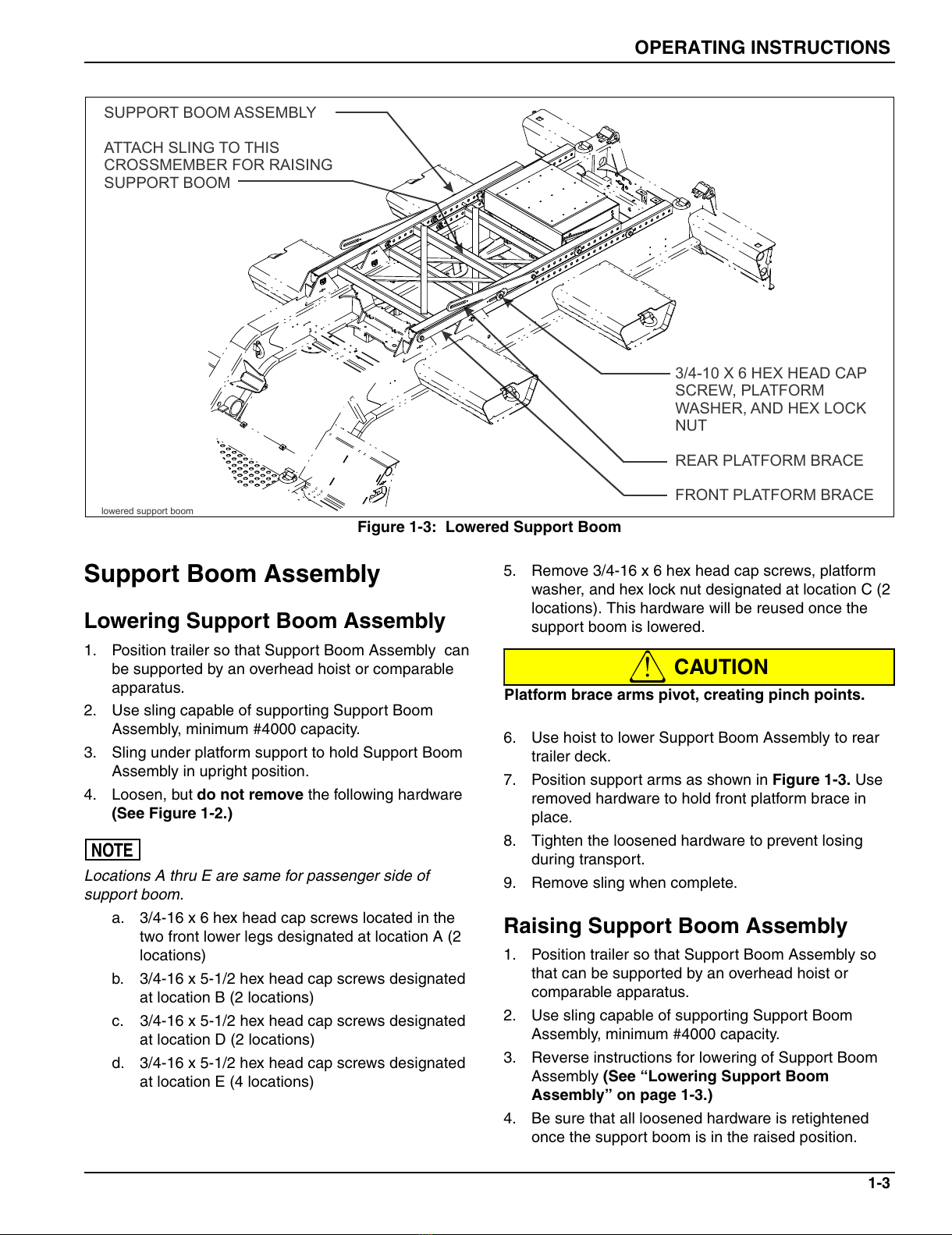
Figure 1-3: Lowered Support Boom
Support Boom Assembly
Lowering Support Boom Assembly
1. Position trailer so that Support Boom Assembly can
be supported by an overhead hoist or comparable
apparatus.
2. Use sling capable of supporting Support Boom
Assembly, minimum #4000 capacity.
3. Sling under platform support to hold Support Boom
Assembly in upright position.
4. Loosen, but do not remove the following hardware
(See Figure 1-2.)
NOTE
Locations A thru E are same for passenger side of
support boom.
a. 3/4-16 x 6 hex head cap screws located in the
two front lower legs designated at location A (2
locations)
b. 3/4-16 x 5-1/2 hex head cap screws designated
at location B (2 locations)
c. 3/4-16 x 5-1/2 hex head cap screws designated
at location D (2 locations)
d. 3/4-16 x 5-1/2 hex head cap screws designated
at location E (4 locations)
5. Remove 3/4-16 x 6 hex head cap screws, platform
washer, and hex lock nut designated at location C (2
locations). This hardware will be reused once the
support boom is lowered.

CAUTION
6. Use hoist to lower Support Boom Assembly to rear
trailer deck.
7. Position support arms as shown in Figure 1-3. Use
removed hardware to hold front platform brace in
place.
8. Tighten the loosened hardware to prevent losing
during transport.
9. Remove sling when complete.
Raising Support Boom Assembly
1. Position trailer so that Support Boom Assembly so
that can be supported by an overhead hoist or
comparable apparatus.
2. Use sling capable of supporting Support Boom
Assembly, minimum #4000 capacity.
3. Reverse instructions for lowering of Support Boom
Assembly (See “Lowering Support Boom
Assembly” on page 1-3.)
4. Be sure that all loosened hardware is retightened
once the support boom is in the raised position.
lowered support boom
SUPPORT BOOM ASSEMBLY
ATTACH SLING TO THIS
CROSSMEMBER FOR RAISING
SUPPORT BOOM
3/4-10 X 6 HEX HEAD CAP
SCREW, PLATFORM
WASHER, AND HEX LOCK
NUT
REAR PLATFORM BRACE
FRONT PLATFORM BRACE
Platform brace arms pivot, creating pinch points.
All manuals and user guides at all-guides.com
1-4 F-718-0313 Edition
OPERATING INSTRUCTIONS
All manuals and user guides at all-guides.com
Equipment from Landoll Corporation is built to exacting
standards ensured by ISO 9001:2008 registration at all
Landoll manufacturing facilities.
Model 855 Boeing
Supplement
Operator’s Manual
Re-Order Part Number F-718-0313
LANDOLL CORPORATION
1900 North Street
Marysville, Kansas 66508
(785) 562-5381
800-428-5655 ~ WWW.LANDOLL.COM
F-718-0313 03/2013
Copyright 2010. Landoll Corporation
"All rights reserved, including the right to reproduce this material or portions thereof in any form"
All manuals and user guides at all-guides.com

Other manuals for 855 FINISHOLL Series

1

Popular Industrial Equipment manuals by other brands

Feltest Capto user manual

Feltest

Feltest Capto user manual

EMB Wallenstein GX600 Operating instructions and parts manual

EMB

EMB Wallenstein GX600 Operating instructions and parts manual

Zimmer GEH6000IL Series Installation and operating instructions

Zimmer

Zimmer GEH6000IL Series Installation and operating instructions

Starrett 3754 user manual

Starrett

Starrett 3754 user manual

SICK SIM2500 operating instructions

SICK

SICK SIM2500 operating instructions

Gomax QUADRA RXA006 instruction sheet

Gomax

Gomax QUADRA RXA006 instruction sheet

LRAD 500X manual

LRAD

LRAD 500X manual

Siemens 3VA911.-0JC12 operating instructions

Siemens

Siemens 3VA911.-0JC12 operating instructions

Blohm + Voss Oil Tools FloorHand 9GF-1102 Technical documentation

Blohm + Voss Oil Tools

Blohm + Voss Oil Tools FloorHand 9GF-1102 Technical documentation

PCB Piezotronics J352C04 Installation and operating manual

PCB Piezotronics

PCB Piezotronics J352C04 Installation and operating manual

Schwarz SB10B operating instructions

Schwarz

Schwarz SB10B operating instructions

SCHUNK Vario D operating manual

SCHUNK

SCHUNK Vario D operating manual

Marshall Excelsior Accu-Max+ Series Installation information

Marshall Excelsior

Marshall Excelsior Accu-Max+ Series Installation information

DUSTLESS BLASTING DB150 user manual

DUSTLESS BLASTING

DUSTLESS BLASTING DB150 user manual

insize ISV-VP280 Operation manual

insize

insize ISV-VP280 Operation manual

Phoenix Contact FL MGUARD 1000 Series Installation and startup guide

Phoenix Contact

Phoenix Contact FL MGUARD 1000 Series Installation and startup guide

KSB 88980/41 Operating and maintenance instructions

KSB

KSB 88980/41 Operating and maintenance instructions

KINSHOFER KM 506 HD operating instructions

KINSHOFER

KINSHOFER KM 506 HD operating instructions

manuals.online logo
manuals.online logoBrands
  • About & Mission
  • Contact us
  • Privacy Policy
  • Terms and Conditions

Copyright 2025 Manuals.Online. All Rights Reserved.