
5-1
4-5
4-4
4-4
4-3
4-3
4-1
3-5
3-3
Free Spool Clutch Operation
Remote Control (Option) 3-10
....................................................................................................................
........................................................................................
..........................................................................................
.................................................................................................................
.......................................................................................
..................................................................................................................
..............................................................................................................
.......................................................................................
(Option)
......................................................................................
........................................................................................................
........................................................................................................................
....................................................................................................................
.................................................................................................................
..................................................................................................
.................................................................................................
................................................................................................
.................................................................................................
...................................................................................................
..............................................................................
....................................................................................................
................................................................................................
.................................................................................................................
...............................................................................................................
................................................................................................................
...........................................................................................
i
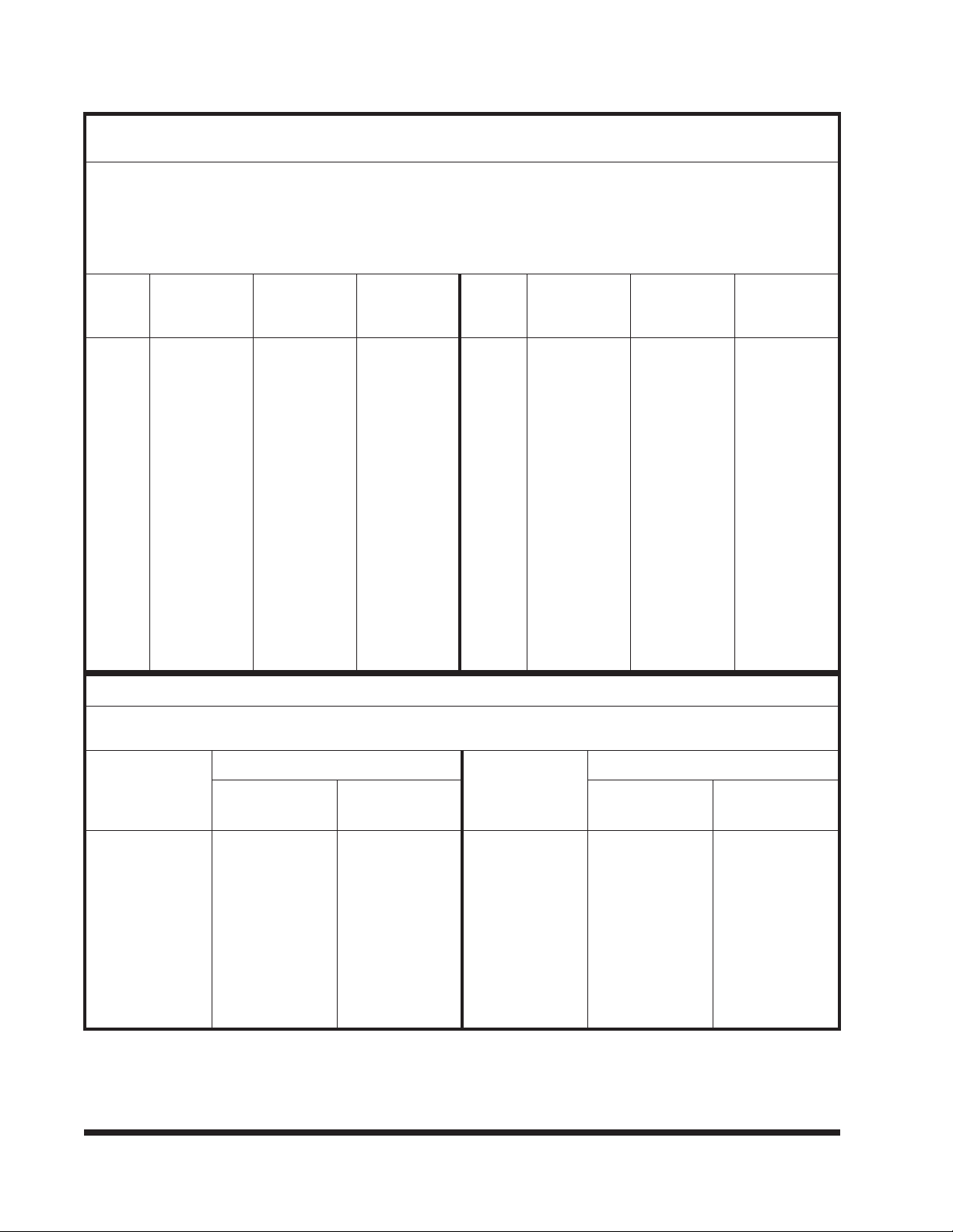
TABLE OF CONTENTS
DESCRIPTION PAGE NO.
INTRODUCTION 1-1
STANDARD SPECIFICATIONS 2-1
OPERATING INSTRUCTIONS 3-1
Bed Tilt Control 3-1
Bed Slide Control 3-4
Winch Controls
Basic Controls 3-5
Special Hitch Control(Option) 3-5
Power Take-off(PTO) 3-5
Bed Loading 3-6
Bed Unloading 3-7
Load Placement 3-7
Securing Loads to Bed 3-7
Hitch Operation(Option) 3-8
Cold Weather Operation 3-11
Hot Weather Operation 3-11
MAINTENANCE and LUBRICATION
Maintenance Schedule
Maintenance Procedures
Frame and Deck
Hydraulic System
Electrical System
TROUBLE SHOOTING GUIDE
Hitch


 Operator's manual")


