L&R 4002 Series User manual

4002 SERIES
ULTRASONIC GENERATOR
OPERATOR'S MANUAL
L&R Manufacturing Company
577 Elm Street
Kearny, NJ 07032-3604 USA
CN 80406 Rev. E

2
TABLE OF CONTENTS
1.0 SYSTEM DESCRIPTION
2.0 OPERATION, WARNINGS AND CAUTIONS
3.0 SPECIFICATIONS
4.0 INSTALLATION PROCEDURE
5.0 DIGITAL TIMER OPERATING INSTRUCTIONS
6.0 SYSTEM CONTROL
7.0 REPLACEMENT PARTS LIST
WARNING: If the equipment is used in a manner not
specified by the manufacturer the protection provided
by the equipment may be impaired.

3
1.0 SYSTEM DESCRIPTION
The 4002 Ultrasonic Generator is a modular design, consisting of a
main controller housing and able to accept from one to three generator
boards. Each board is capable of driving a separate immersible
transducer module, or a group of transducers bonded to a tank.
Generator modules can be individually or simultaneously operated
with timer. Features include constant power output circuitry, as well
as short circuit protection.
The ST versions of the 4002 ultrasonic generator incorporate sweep circuit
technology which varies the operating resonant frequency ±2 KHZ at a user
adjustable rate ranging from 1-100 Hz.
2.0 WARNINGS & CAUTIONS
WARNING: Ground unit properly, connect safety ground wire to approved Earth
Ground, Connect power to an approved supply source with ground, Do not operate
or apply power to a system until ALL Protective Earth (PE) grounds have been
connected.
WARNING:Avoid use of flammable solutions such as gasoline, benzene, benzol,
etc. in cleaning tank.
WARNING:Disconnect all Mains Power prior to any service
WARNING:Insure proper system grounding.
Keep area and equipment dry and clean.
WARNING: Do not open generator while unit is plugged in. Dangerous high voltages are
present.
CAUTION:Do not operate system without cleaning solution in tank. Solution level
must be at least 3 inches above transducer for non heated units and at least 3 inches
from the tank rim on heated units..
Do not overfill tank.
Allow clearance at front and rear of generator for air flow.
Always turn unit OFF when not in use.
Keep top of transducer free of debris and any accumulated dirt or sludge.
WARNING:Service must be done by competent personnel only.
Caution: Hearing protection required for operator as designated by local safety codes.
OPERATION WARNINGS
AND CAUTIONS:

4
3.0 SPECIFICATIONS
SYSTEM CONTROL: Individual section ON/OFF power switch. "Ultrasonics On" indicator
light. 99 minute digital timer with L.E.D. standard display. Optional 99
Hour Timer Control. Optional Remote Control. Sweep rate adjustment,
ST version, power control (optional). Wattmeter (optional).
ULTRASONIC FREQUENCY: 43 KHz. Opt. Sweep Range: +/- 2Khz, Sweep Rate: 1—100 Hz
Generator Overall Dimensions:
Last digit in model number may be 6, 5, 4, 3 or a suffix of ST.
MODEL
NUMBER
PRODUC
T
CODE
Voltag
e
BOARD
SECTIONS
TOTAL
POWER Main FUSE Data CURRENT
REQUIREMENTS
4002-1/6 17677
17678
117
230
1
1
600 W
600 W
T10.0A/250V
T5.0A/250V
5.1A 110V
2.7A 230V
4002-2/6 17685
17686
117
230
2
2
1200 W
1200 W
T20.0A/250V
T10.0A/250V
10.2A 110V
5.4A 230V
4002-3/6 17693
17694
117
230
3
3
1800 W
1800 W
T30.0A/250V
T15.0A/250V
15.3A 110V
8.1A 230V
4002-1/5 17679
17680
117
230
1
1
500 W
500 W
T10.0A/250V
T5.0A/250V
4.3A 110V
2.3A 230V
4002-2/5 17687
17688
117
230
2
2
1000 W
1000 W
T20.0A/250V
T10.0A/250V
8.6A 110V
4.6A 230V
4002-3/5 17695
17696
117
230
3
3
1500 W
1500 W
T30.0A/250V
T15.0A/250V
12.9A 110V
6.9A 230V
4002-1/3 17683
17684
117
230
1
1
300 W
300 W
T10.0A/250V
T5.0A/250V
2.7A 110V
1.36A 230V
4002-1/4 17681
17682
117
230
1
1
400 W
400 W
T10.0A/250V
T5.0A/250V
3.6A 110V
1.8A 230V
4002ST-1/6 18245
18246
117
230
1
1
600 W
600 W
T10.0A/250V
T5.0A/250V
5.1A 117V
2.7A 230V
4002ST-2/6 18261
18262
117
230
2
2
1200 W
1200 W
T20.0A/250V
T10.0A/250V
10.2A 117V
5.4A 230V
4002ST-3/6 18277
18278
117
230
3
3
1800 W
1800 W
T30.0A/250V
T15.0A/250V
15.3A 117V
8.1A 230V
4002ST-1/5 18241
18242
117
230
1
1
500 W
500 W
T10.0A/250V
T5.0A/250V
4.3A 117V
2.3A 230V
4002ST-2/5 18257
18258
117
230
2
2
1000 W
1000 W
T20.0A/250V
T10.0A/250V
8.6A 117V
4.6A 230V
4002ST-1/3 18233
18234
117
230
1
1
300 W
300 W
T10.0A/250V
T5.0A/250V
2.7A 117V
1.4A 230V
Note: Board section fuse is T10.0A/250V for 117 volt units and T5.0A/250V for 230 volt units
** Generator line frequency is 50/60 Hz
*** Do Not position equipment so that it is difficult to operate the disconnecting device.
**** Disconnect unit from mains by unplugging the line cord.
4002-1/6 9.2”Wx8”Hx17.7D 18Lbs
4002-2/6 14”Wx8”Hx17.7”D 28Lbs
4002-3/6 22”Wx8”Hx17.7”D 38Lbs
Model Number * Overall Size Weight

5
3.1 ENVIRONMENTAL:
Allow 3” behind generator for cable, connectors and air flow.
Generator to be located in a dry location, 0-35°C, RH 96% Non-Condensing
non-corrosive atmosphere below 2000 M altitude.
Units can be stacked or stand side by side (min. 2” between sides). DO NOT
place units other ways.
4.0 INSTALLATION PROCEDURE:
After carefully removing the system from its carton
and box, remove all packing material and place the
generator on a convenient surface away from liquid
splash, allowing for air-flow at front and rear of
generator.
With the AC line-cord disconnected and power switch
in the OFF position, connect transducer ultrasonic
cable to rear of generator.
Fill tank with recommended L&R solution properly
diluted, or equivalent, to proper level (minimum of 3
inches above top of transducer for non heated system
and no less than 3 inches from the top for a heated tank). Note that solution displacement,
when submerging part to be cleaned, must be taken into account. Prevent the solution level
from getting lower than the minimum to prevent heater failure or transducer failure. Turn heater
and ultrasonic power off before draining tank.
Plug generator's AC line-cord into a suitable 3 wire grounded outlet (see power
requirement). Unit grounding is essential for operator's safety. On units with a separate
grounding wire connect the ground wire to the receptacle ground first.
5.0 DIGITAL TIMER OPERATING INSTRUCTIONS
Minimum operating time is 2 seconds, maximum 99 minutes 59 seconds.
Functionally Using the Timer
[Start/Resume]
BUTTON
Decimal point of
3-seven segment
Mode LEDs
3421
[Set/Display]
1-seven segment
Decimal point of
BUTTON
[Stop]
BUTTON
[Mode]
BUTTON
BUTTON
[Increase]
[Decrease]
BUTTON
Clock set LEDRun LED

6
1. After applying an appropriate AC to the power input terminals, the display will be blank and
the beeper will beep for ¼ second giving the user notification that the timer is now activated.
The units’ default is in Minute [Mode].
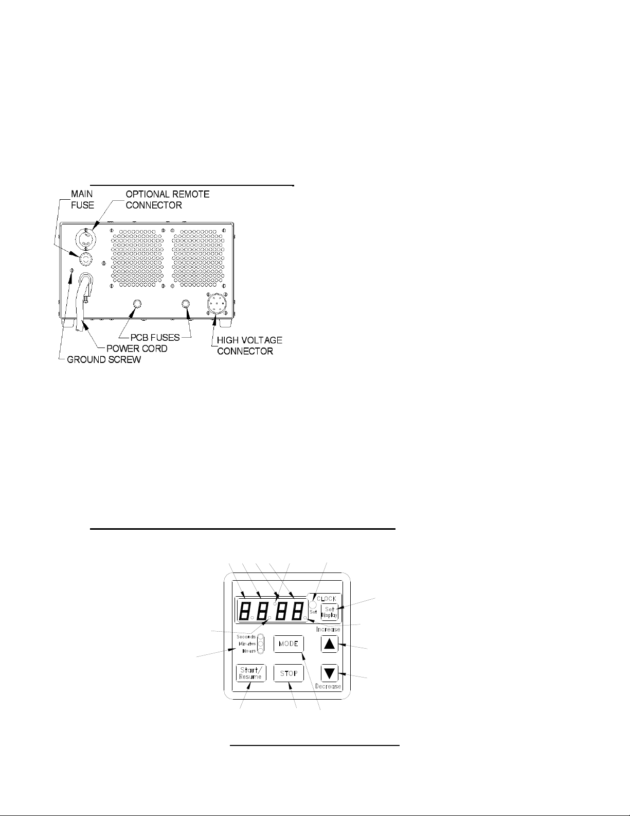
2. Setting Time of Day - Push and hold the button [SET/DISPLAY] for 1 second, the unit will
default the time to 12:00am and enter the ‘Clock Set’ mode. While in this mode, buttons
[MODE], [STOP] & [START/RESUME] are disabled and the clock set LED will be turned ON.
The user now can set the time by pressing and holding either [INCREASE] or [DECREASE]
button until the desired time is achieved. If you do not wish to set the time of day,
skip step number 3.
The clock mode is a 12-hour with an am/pm display element. When the clock is being
displayed and the clock is in the pm time frame, the decimal point of number 1-seven segment
will be ON. Once the user has achieved the proper clock value, they need to exit the clock set
mode by pressing and holding the button [SET/DISPLAY] for 1 second. After the 1 second, the
beeper will beep for 1 second giving the user notification that the mode is now exited. Once the
clock is set, the display will go blank and the clock set LED will turn OFF.
If the clock has been set and the user presses the button [SET/DISPLAY] for less than 1
second, the display will show the current time for a 5 second period and revert back to what
was previously on the display.
3. Setting Interval Timer - In modes 1 – 3, the device functions as a simple countdown timer.
When you set the value, press the button [START/RESUME]. When the value reaches 0, the
relay is turned OFF and the beeper beeps 6 sets of 2 (250ms) beeps.
Repeat Feature- the timer will remember the last time set. If you desire to change the setting
from the original setting, press start switch to recall previous setting then input new setting.
To enter one of the 3 countdown modes, press and hold the button [MODE] for 1 second.
Holding down this button the mode will switch every 2 seconds. Each time the mode switches,
the appropriate LED of mode LEDs will be turned ON and the value displayed will change to
the modes default value. An audible ¼ beep will also be heard.
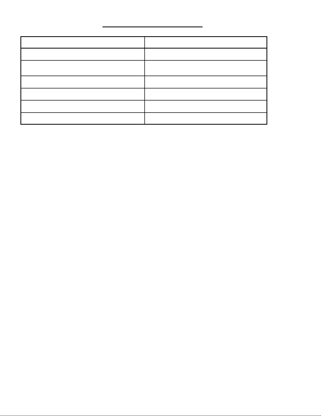
Mode 1 0 – 99 second: DEFAULT DISPLAY = 01
Mode 2 0 – 99 minute: DEFAULT DISPLAY = 00.00
Mode 3 0 – 99 hour: DEFAULT DISPLAY = 00.00
Once the countdown value has been set, you can now start the timer by pressing the button
[START/RESUME]. The relay is turned ON. While the timer is counting down the user can
stop the event by pressing the button [STOP]. The current countdown value will remain on
the display. If you want to resume the session you just need to press the start button again.
Counting will proceed from the point where stopped. During this operation, the run LED is
blinked at once a second.
Once the timer has counted down to 0 and stopped, you can execute the same session (time
value) by pressing the [START/RESUME] button again. This will recall the timer value and
display it. At this point, you have two options. The first being the ability to change the value
by using the [INCREASE] or [DECREASE] buttons and the second being the ability to use
the same value and starting the event again by pressing the [START/RESUME] button.

7
6.0 SYSTEM CONTROL
iindividual section ON/OFF power switch (not applicable on Single Generator). This
switch is capable of turning the power
on or off for a single generator section
independent of the remaining sections.
Ultrasonics On - Indicator light
This pilot light is an indicator of the
Ultrasonic Power going to the Ultrasonic
tank. If the power is decreased then the
light dims, if the power is increased then
the light brightens. During normal
operation the light can be seen to
pulsate - this pulsation is due to normal load fluctuations and the power regulation
of the generator. Sweeping systems cause this light to pulsate due to it’s continuous
adjustment.
Timer 99 - minute digital timer with L.E.D. (standard display).
ST Version (Sweep Option).
Sweep rate adjustments. The sweep rate is adjustable from 1 Hz to 100 Hz via the
front panel control knob. This control changes the sweep rate of all the generators
simultaneously. This control adjusts the rate at which the generator changes it’s
sweep range (43 Khz +/- 2 Khz). For example, if the sweep rate knob was set to
minimum the generators would sweep their frequency from 41 Khz to 45 Khz and
then back to 41 Khz all in one second - this would be a sweep rate of 1. if the
sweep rate was set to a maximum the generators would sweep their frequency from
41 Khz to 45 Khz and then back to 41 Khz one hundred times a second, this would
be a sweep rate of 100.
Power Control (Optional).
Each generator has a power control function knob. This adjustment serves to select
an operational power for the generator section from approximately 50%to 100% of
the generator’s power capability.
This parameter is adjusted to optimize the cleaning process to suite the need of the
cleaning application. Hard cleaning of stubborn crud on the firearm usually require
maximum power. General experience has shown that once a satisfactory setting
has been selected that there is no further adjustment required.
Wattmeter (Optional).
The wattmeter section has a digital readout that displays the power of the selected
generator section. There is a power meter selection knob mounted under the power
meter. Set the knob to the position that corresponds to the system, the wattmeter
can change +/- 10%. This change is due to the load change, sweeping and the
generator CPO feature that constantly regulates the generator power to set the
value.
TIMER
WATTMETER
INDICATOR LIGHT
POWER CONTROL
ON/OFF SWITCH
SELECTOR
SWEEP RATE
CONTROL

8
7.0REPLACEMENT PARTS LIST
DESCRIPTION C/N
FUSE HOLDER 30129
FUSE 5 AMP 31591
FUSE 10 AMP 30126
FUSE 15 AMP 32291
FUSE 20 AMP 30128
FUSE 30 AMP 31913

9
Please Record:
Serial # ___________
Order Date ________
One Year Limited Warranty
L&R Manufacturing Company warrants this product for a period
of one year from the date of purchase to be free of defects in
material and workmanship. Machine will be repaired free of
charge to the customer during the warranty period.
This warranty does not include damage or product
failure resulting from misuse, abuse or transportation
damage. Operating the machine dry is the most
common misuse which results in failure.

10
REVISION HISTORY
C/N 80406
REVISION ECN# DESCRIPTION APPROVED DATE
C 8294 SEE ECN J.P.M. 01/22/2007
D 8316 REVISED SHEET 4,
SEE ECN 8316.
J.P.M. 01/24/2007
E 8725 REVISED SHEET 5
2000 M was 2000 Ft
J.P.M. 11/17/2010
This manual suits for next models
14
Table of contents