Page A - 2
A
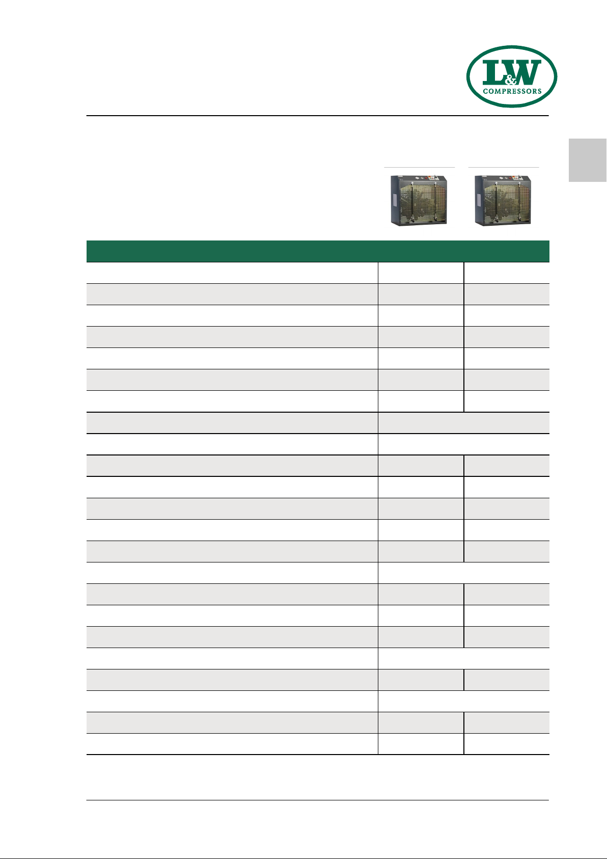
LW SC-300 E / LW SC-350 E
Version: 06.12.2022
T A B L E O F C O N T E N T S
General Information and Technical Data
General Information / Description of Warning Symbols .................................................................... 4
Scope of Delivery .............................................................................................................................. 5
Technical Data .................................................................................................................................. 6
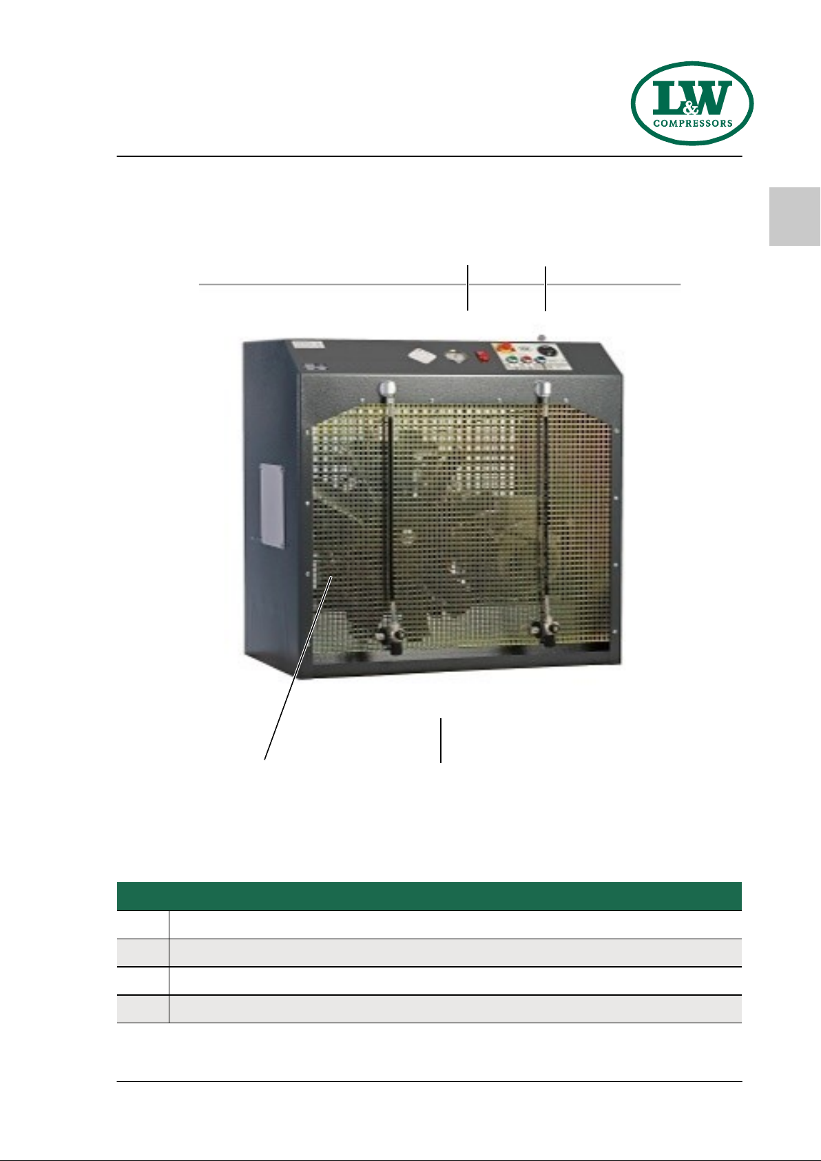
Unit Assembly ................................................................................................................................... 7
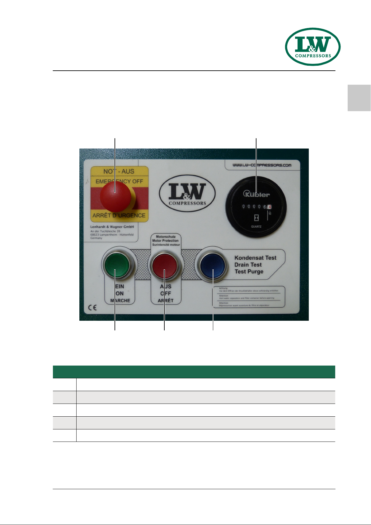
Switchboard ..................................................................................................................................... 8
Flow chart ......................................................................................................................................... 9
Safety Precautions
Intended Use / Operators ................................................................................................................ 11
Safety instructions on the unit ........................................................................................................ 12
General Safety Precautions ............................................................................................................. 13
Unit customised safety notices ........................................................................................................ 14
Maintenance instructions ................................................................................................................ 15
Transportation instructions / Safety regulations .............................................................................. 16
Installation
Installation in closed rooms ............................................................................................................ 18
Dimensions ...................................................................................................................................... 19
Minimum distances ......................................................................................................................... 20
Ventilation ...................................................................................................................................... 21
Electrical Installation ................................................................................................................ 22 - 23
Operation
Important operation instructions .................................................................................................... 25
First commissioning ................................................................................................................. 26 - 28
Daily commissioning ....................................................................................................................... 29
Filling procedure ............................................................................................................................. 30
Switch off the compressor .............................................................................................................. 31
Remedying faults .............................................................................................................. 32 - 36
Maintenance and Service
Service, Repair and Maintenance .................................................................................................... 38
Maintenance Lists / Maintenance Intervals ............................................................................... 39 - 42
Check V-belt tension / Tension V-belt ............................................................................................... 43
Compressor lubrication / Check oil level .......................................................................................... 44
Oil change ...................................................................................................................................... 45
Oil filter maintenance ..................................................................................................................... 46
Final pressure switch ....................................................................................................................... 47