Laney LFR-412 User manual


Page 1
CONTENTS
INTRODUCTION ................................................................................................................................................ 2
FEATURES ...................................................................................................................................................... 2
CONTROLS......................................................................................................................................................... 3
CONNECTING THE LFR-412 ............................................................................................................................ 5
CONNECTING THE INPUTS......................................................................................................................... 5
CONNECTING THE DI OUT......................................................................................................................... 5
CONNECT TWO LFR-412 ............................................................................................................................ 6
CONNECT TO PC VIA USB .......................................................................................................................... 6
SPECIFICATIONS ............................................................................................................................................... 7
BLOCK DIAGRAM ......................................................................................................................................... 8
DIMENSIONS (in mm)................................................................................................................................... 9
SAFETY AND WARNINGS...............................................................................................................................11

Page 2
INTRODUCTION
Laney are the first amplifier brand to develop a REAL solution for players using a digital rig, providing
players with a stylish and imposing sound presence on stage.
As that market has grown, so too has the LFR’s reputation as the market leader in powered full range,
flat response (FRFR) guitar cabinets.
Following the huge success of our LFR-112 and LFR-212 powered cabinets, we’ve decided to offer up
the World’s first 4x12 dedicated FRFR guitar cabinet. The LFR-412
The LFR-412 offers you an incredible 2600 Watts, an industry leading and best in class powered
cabinet filled with output options. Ensuring the perfect partnership for whichever profiler you choose
to pair it with.
The LFR-412 features LA⋅IR (Laney Advance Impulse Response) technology that uses 56bit FIR filters
to provide stunning cabinet emulations. The LFR-412 ships with two IRs (Impulse Responses)
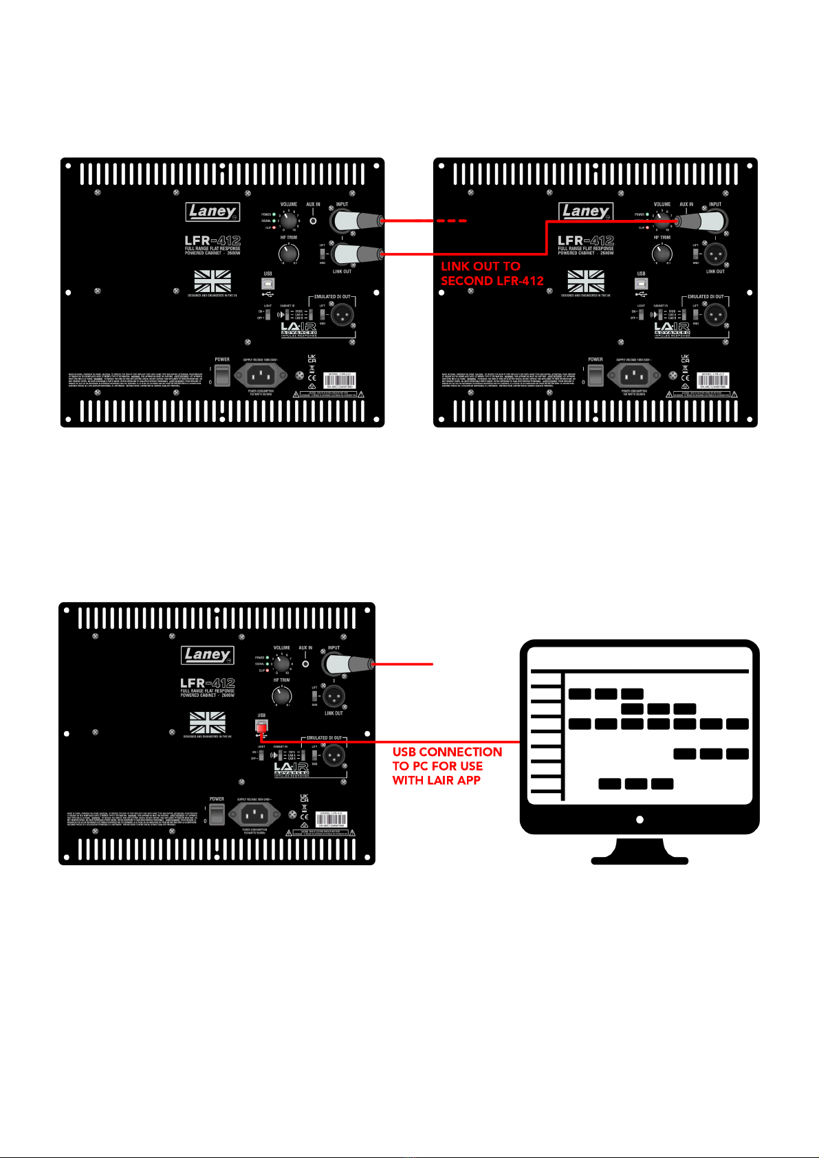
designed and used by the legendary guitarist Devin Townsend. The USB connectivity allows you to
load your own IRs, and the LA⋅IR LFR app allows for further adjustment. Housing the IR in the cabinet
frees up processing power within your digital rig, allowing for greater creativity and reliability. In
short; the LFR-412 does the heavy lifting.
The LFR-412 joins a range of Laney LFR powered cabinets that all feature tailor-made drivers,
designed and engineered by HH Acoustics to deliver power, precision and importantly a response
that gives you the feeling of a real guitar cabinet by your side. Why is this so? Well, with over 55 years
of amplification and cabinet design experience, we understand the thrill of feeling the air move to
you, the player, and your amp and cab. The LFR-412 offers an authentic response that feels familiar to
you in comparison to other options on the market.
These FRFR powered cabinets are raising the bar and redefining the standards that you expect from
your digital rig, all in an aesthetic package that guarantees to turn heads.
FEATURES
•2600W Higher Power Asymmetric Class-D Power Amplifier
•LA∙IR Dual Selectable High quality Digital IR for Cabinet and XLR out
•LA∙IR is Laney Advance Impulse Response technology, using 56bit FIR filters to provide high quality
cabinet emulation
•Ultra Low Noise Design
•High Dynamic Range allows for hot and cold signal levels in
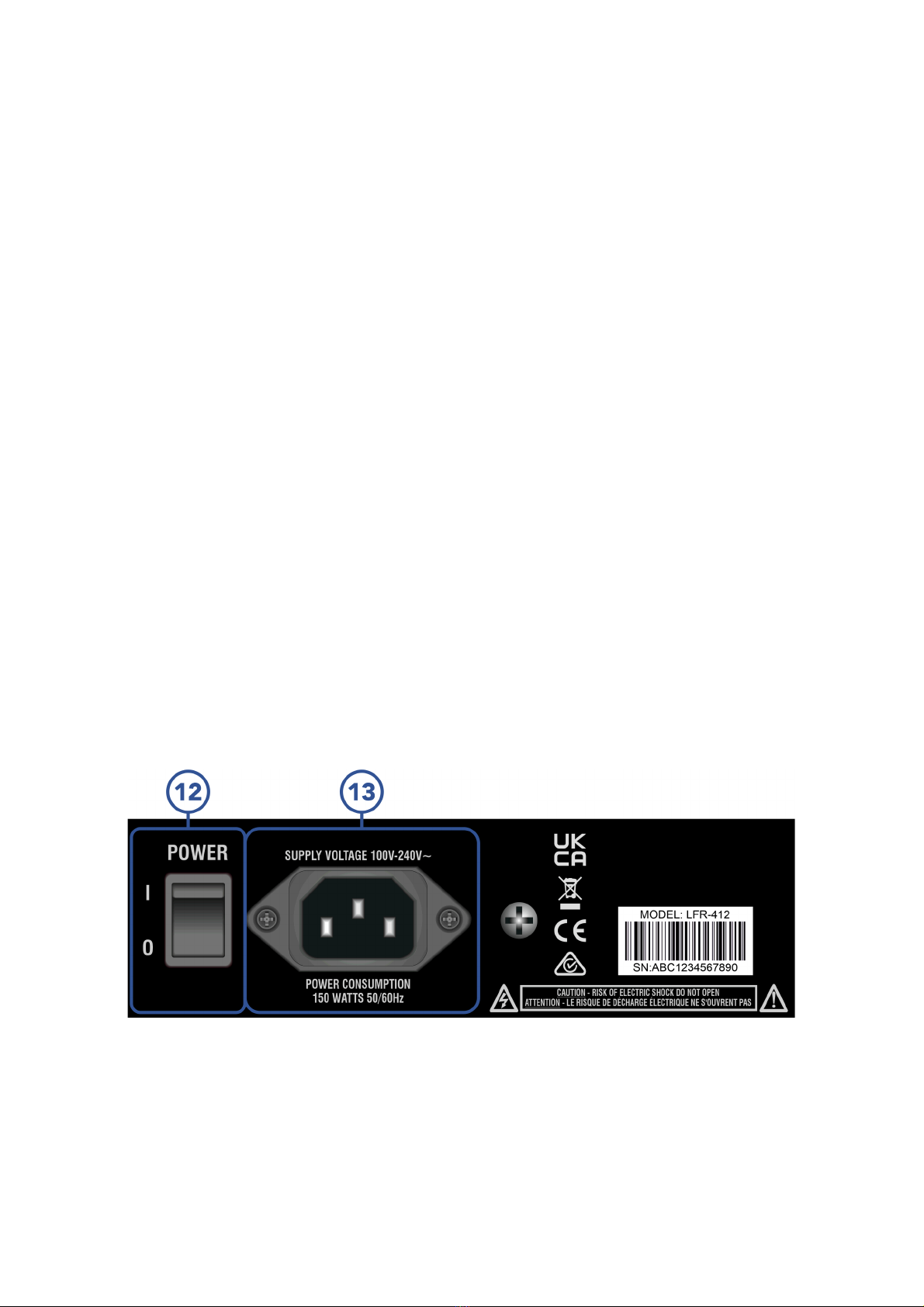
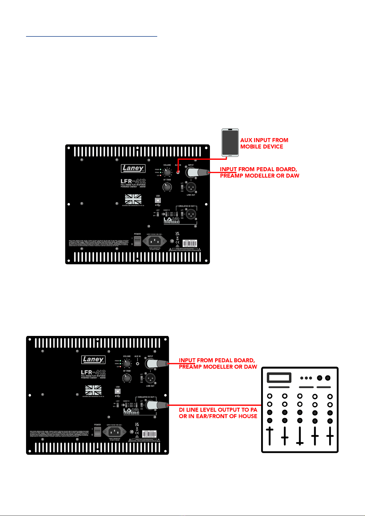
•Comprehensive Inputs and Outputs
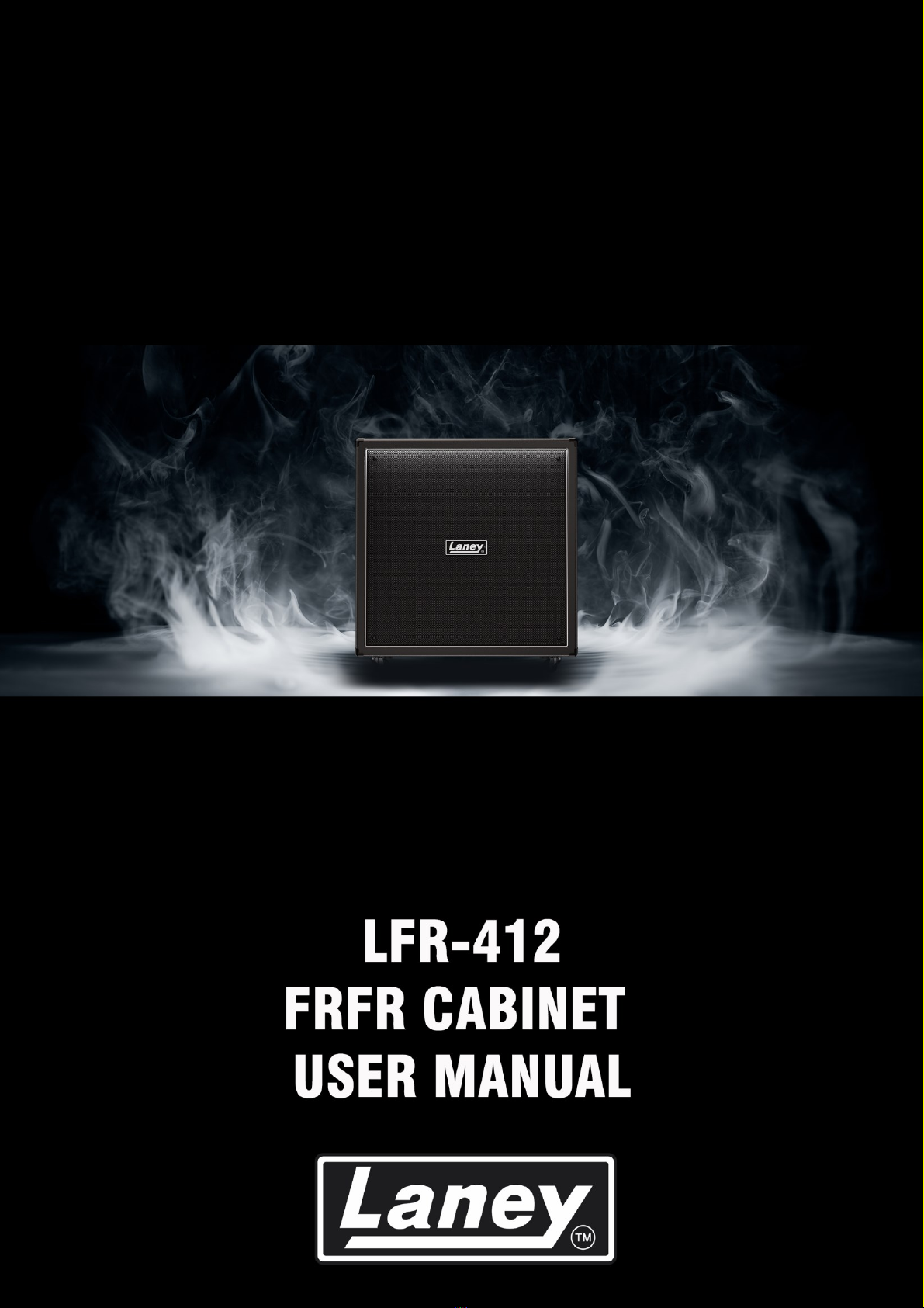
•Volume and HF trim controls
•USB type B interface to adjust IR presets and cabinet EQ through the supplied LA∙IR LFR app
•Road Ready Plywood Construction
•HH Designed Professional Loudspeakers
•100-240V Universal Voltage, IEC C14, lead included
•USB Type-B to Type-A cable included, as well as Type-A to Type-C adapter

Page 3
CONTROLS
1. VOLUME CONTROL
Volume attenuator for signal input to the LFR-412. Will mute at 0, and should be turned down if the
SIGNAL LED is lit red. Note that the aux input bypasses this volume control.
2. 3.5mm STEREO AUX INPUT SOCKET
Audio input socket intended for adding backing tracks to your playing. Bypasses the volume control
and any loaded IRs and EQ.
3. POWER AND SIGNAL LEDS
-Power LED will light green whenever the LFR-412 is plugged in and powered on.
-Signal LED will light green whenever the LFR-412 detects a signal present at the input socket.
This will turn red when a signal begins clipping at the preamp stage. Avoid this ever turning
red by turning down the volume or input level.
-Clip LED will light red when the internal amplifier is clipping. This is ok for a short while but
should be avoided over longer periods of time.

Page 4
4. INPUT SOCKET
A balanced XLR / 6.3mm jack combi socket for your main audio signal input. Ideally use with a
balanced audio line, especially over long cable distances, to avoid noise interference. The LFR-412
features HDR technology to accommodate for a range of line input levels.
5. HF TRIM CONTROL
Tailor the cabinets high frequency response to your environment. A HF shelving filter set at 3kHz,
increase or decrease the high end of your signal quickly and easily.
6. LINK OUT W/ GROUND LIFT
Link out XLR socket that directly returns your input signal with no alteration whatsoever. Link to
another active cab to extend your system further. A ground lift switch is included to potentially reduce
any ground hum.
7. USB TYPE B SOCKET
Connect the provided USB-B to USB-A cable to a Windows or Mac PC to access the LFR-412’s IR
presets and cabinet EQ via the downloadable LA∙IR LFR app.
8. FRONT LED STRIP SWITCH
Turn on and off the LED downlight strip found on the front panel of the LFR-412 cabinet.
9. CABINET IR SWITCH
Load an IR preset for the LFR-412 cabinet. Choose from FRFR (completely flat EQ), CAB A or CAB B –
preset IRs that can be modified through the LA∙IR LFR app.
10. DI OUT IR SWITCH
Load an IR preset for the DI out. Choose from FRFR, CAB A or CAB B –preset IRs that can be modified
through the LA∙IR LFR app.
11. EMULATED DI OUT W/ GROUND LIFT
A balanced XLR output socket at line level. The EQ and gain of this channel can be modified in the
LA∙IR LFR app. Ground lift switch included to potentially reduce ground hum.
12. POWER SWITCH
Turns the LFR-412 on and off when the correct power lead is connected.
13. MAINS INLET SOCKET
Universal IEC input to connect the provided mains lead.

Page 5
CONNECTING THE LFR-412
CONNECTING THE INPUTS
The Laney LFR-412 has two input sockets. An XLR / 6.3mm combi jack for your balanced guitar signal
input as well as a 3.5mm aux in to connect a backing track via a media player such as your mobile
phone. The aux in is post volume, user EQ and IR emulation so will not be affected by any tone
changes.
Thanks to the LFR-412’s high dynamic range, the input can accept hot and cold line level signals. Just
make sure the signal LED doesn’t turn red as this indicates the front end is clipping, which can cause
long term damage to the LFR-412.
CONNECTING THE DI OUT
The XLR DI-out provides a balanced line level output to connect to your PA, front of house or in ear
monitors. Unaffected by the volume or trim controls, the DI out has it’s own cabinet emulation and
user loaded EQ that applies separately to the cabinet EQ/IR’s.

Page 6
CONNECT TWO LFR-412
Two LFR-412’s can be connected together via the link out provided. An XLR socket direct from the
input, connect this to another LFR-412’s input socket. Note that the LFR-412 is stackable, allowing two
units to be placed on top of one another
CONNECT TO PC VIA USB
Connect to a Windows or Mac computer via the USB Type-B socket. A Type-B to Type-A cable is
provided as well as a Type-A to Type-C adapter depending on your computer’s USB ports.
From here you can download the LA⋅IR LFR app provided by Laney, to load your own IRs and tweak
the 8 band EQ for both the cabinet itself and the DI-out. Change these on the fly whilst playing to
hear your changes live and save these for later use when gigging or practicing.

Page 7
SPECIFICATIONS
Model
LFR-412
Type
Full Frequency Range Flat Response Powered 4x12" Cabinet
Frequency response (-3)
48-18kHz
Max SPL (1M)
135 dB SPL, 138 dB SPL (Peak)
Power Rating
2600W Peak, 1300W Continuous, 650W RMS
Input
Balanced Female XLR/Jack Combi, 3.5mm Stereo aux in
Output
Balanced Male XLR DI Out, Balanced Male XLR Link Out
Controls
Volume, HF Trim, Speaker and DI out Emulation Switch, Ground lift, Light switch.
Other
USB type B socket for access to LAIR app, allows IR loading, EQ adjustment.
Illumination
Front illuminated downlight strip
HF Driver
1" LaVoce DF10 Horn
LF Driver
4x 12" HH Designed Black Series 30050 Professional Woofers
Crossover Frequency
3kHz
Enclosure
15mm Plywood Construction. Twin Sealed Chambers
Handles
Side Mounted, easy grab steel bar handles
Castors
Removeable, Push Fit Castors Included. (Castor Cups allow easy stacking)
Finish
Hard wearing black vinyl, Black Metal Corners
Unit dimensions (HWD)
820 x 770 x 365mm, 32.3" x 30.3" x 14.4"
Unit weight
43.3Kg, 95.5 lbs
Carton dimensions
(HWD)
920 x 880 x 480mm, 36.2" x 34.6" x 18.9" , 0.389 M3
EAN Code
5060109458787

Page 8
BLOCK DIAGRAM

Page 9
DIMENSIONS (in mm)

Page 10
STACKED DIMENSIONS (in mm)

Page 11
SAFETY AND WARNINGS
In order to take full advantage of your new product and enjoy long and trouble-free performance, please read this owner's manual carefully,
and keep it in a safe place for future reference.
1) Unpacking: On unpacking your product please check carefully for any signs of damage that may have occurred whilst in transit from the
Laney factory to your dealer. In the unlikely event that there has been damage, please re-pack your unit in its original carton and consult
your dealer. We strongly advise you to keep your original transit carton, since in the unlikely event that your unit should develop a fault,
you will be able to return it to you dealer for rectification securely packed.
2) Amplifier Connection: In order to avoid damage, Generally it is advisable to establish and follow a pattern for turning on and off your
system. With all system parts connected, turn on source equipment, mixers, effects processors etc, BEFORE turning on your amplifier.
Many products have large transient surges at turn on and off which can cause damage to your speakers. By turning on your amplifier
LAST and making sure its level control is set to a minimum, any transients from other equipment should not reach your loud speakers.
Wait till all system parts have stabilised, usually a couple of seconds. Similarly when turning off your system always turn down the level
controls on your amplifier and then turn off its power before turning off other equipment.
3) Cables: Never use shielded or microphone cable for any speaker connections as this will not be substantial enough to handle the
amplifier load and could cause damage to your complete system. Use good quality shielded cables everywhere else.
4) Servicing: The user should not attempt to service these products. Refer all servicing to qualified service personnel.
5) Heed all warnings.
6) Follow all instructions.
7) Do not use this apparatus near water.
8) Clean only with a dry cloth.
9) Do not block any of the ventilation openings. Install in accordance with manufacturer’s instructions.
10) Do not install near any heat sources such as radiators, heat registers, stoves or other apparatus (including amplifiers) that produce heat.
11) An apparatus with Class I construction shall be connected to a mains socket outlet with a protective connection. Do not defeat the safety
purpose of the polarized or grounding-type plug. A polarized plug has two blades with one wider than the other. A grounding type
plug has two blades and a third grounding prong. The wide blade or third prong is provided for your safety. If the provided plug does
not fit into your outlet, consult an electrician for replacement of the obsolete outlet.
12) Protect the power cord from being walked on or pinched, particularly at plugs, convenience receptacles, and the point they exit from
the apparatus.
13) Only use attachments/accessories provided by the manufacturer.
14) Use only with a cart, stand, tripod, bracket, or table specified by the manufacturer, or sold with the apparatus. When a cart is used, use
caution when moving the cart/apparatus combination to avoid injury from tip-over.
15) The mains plug or appliance coupler is used as the disconnect device and shall remain readily operable. The user should allow easy
access to any mains plug, mains coupler and mains switch used in conjunction with this unit thus making it readily operable. Unplug this
apparatus during lightning storms or when unused for long periods of time.
16) Refer all servicing to qualified service personnel. Servicing is required when the apparatus has been damaged in any way, such as when
power-supply cord or plug is damaged, liquid has been spilled or objects have fallen into the apparatus, the apparatus has been
exposed to rain or moisture, does not operate normally, or has been dropped.
17) Never break off the ground pin. Connect only to a power supply of the type marked on the unit adjacent to the power supply cord.
18) If this product is to be mounted in an equipment rack, rear support should be provided.
19) Note for UK only: If the colours of the wires in the mains lead of this unit do not correspond with the terminals in your plug‚ proceed as
follows:
oThe wire that is coloured green and yellow must be connected to the terminal that is marked by the letter E‚ the earth symbol‚
coloured green or coloured green and yellow.
oThe wire that is coloured blue must be connected to the terminal that is marked with the letter N or the colour black.
oThe wire that is coloured brown must be connected to the terminal that is marked with the letter L or
the colour red.
20) This electrical apparatus should not be exposed to dripping or splashing and care should be taken not to
place objects containing liquids, such as vases, upon the apparatus.
21) Exposure to extremely high noise levels may cause a permanent hearing loss. Individuals vary considerably in
susceptibility to noise-induced hearing loss, but nearly everyone will lose some hearing if exposed to
sufficiently intense noise for a sufficient time. The U.S. Government’s Occupational Safety and Health
Administration (OSHA) has specified the following permissible noise level exposures: According to OSHA, any
exposure in excess of the above permissible limits could result in some hearing loss. Earplugs or protectors to
the ear canals or over the ears must be worn when operating this amplification system in order to prevent a permanent hearing loss, if
exposure is in excess of the limits as set forth above. To ensure against potentially dangerous exposure to high sound pressure levels, it
is recommended that all persons exposed to equipment capable of producing high sound pressure levels such as this amplification
system be protected by hearing protectors while this unit is in operation.
22) If your appliance features a tilting mechanism or a kickback style cabinet, please use this design feature with caution. Due to the ease
with which the amplifier can be moved between straight and tilted back positions, only use the amplifier on a level, stable surface. DO
NOT operate the amplifier on a desk, table, shelf or otherwise unsuitable non-stable platform.
23) Symbols & nomenclature used on the product and in the product manuals, intended to alert the operator to areas where extra caution
may be necessary, are as follows:

Page 12
Intended to alert the user to the presence of uninsulated ‘Dangerous Voltage’ within the products enclosure
that may be sufficient to constitute a risk of electrical shock to persons.
Ce symbole est utililise pur indiquer a l’utilisateur de ce produit de tension non-isolee dangereuse pouvant
etre d’intensite suffisante pour constituer un risque de choc electrique.
Este simbolo tiene el proposito de alertar al usuario de la presencia de ‘(voltaje) peligroso’ que no tiene
aislamiento dentro de la caja del producto que puede tener una magnitud suficiente como para constituir
riesgo de corrientazo.
Dieses Symbol soll den Anwender vor unsolierten gefahrlichen Spannungen innerhalb des Gehauses warnen,
die von Ausrichender Starke sind, um einen elektrischen Schlag verursachen zu konnen.
Intended to alert the user of the presence of important operating and maintenance (Servicing) instructions in
the literature accompanying the product.
Dieses Symbol soll den Anwender vor unsolierten gefahrlichen Spannungen innerhalb des Gehauses warnen,
die von Ausrichender Starke sind, um einen elektrischen Schlag verursachen zu konnen.
Este simbolo tiene el proposito de la alertar al usario de la presencis de instrucccones importantes sobre la
operacion y mantenimiento en la literatura que viene conel producto.
Dieses Symbol soll den Benutzer auf wichtige Instruktionen in der Bedienungsanleitung aufmerksam machen,
die Handhabung und Wartung des Produkts betreffen.
CAUTION: Risk of electrical shock - DO NOT OPEN. To reduce the risk of electrical shock, do not remove the cover. No
user serviceable parts inside. Refer servicing to qualified personnel.
ATTENTION: Risques de choc electrique - NE PAS OUVIRIR. Afin de reduire le risque de choc electrique, ne pas enlever le
couvercle. II ne se trouve a l’interieur aucune piece pouvant etre reparee par l’utilisateur. Confier l’entretien a
un personnel qualifie.
PRECAUCION: Riesgo de corrientazo - no abra. Para disminuir el risego de carrientazo, no abra la cubierta. No hay piezas
adentro que el pueda reparar. Deje todo mantenimiento a los tecnicos calificadod.
VORSICHT: Risiko - Elektrischer Schlag! Nicht offen! Um das Risiko eines elektrischen Schlages zu vermeiden, nicht die
Abdeckung enfernen. Es befinden sich keine Teile darin, die vow Anwender repariert werden Konnten.
Reparaturen nur von qualifiziertem Fachpersonal durchfuhren lassen.
WARNING: To prevent electrical shock or fire hazard, do not expose this appliance to rain or moisture. Before using this
appliance please read the operating instructions for further warnings.
ADVERTISSEMENT: Afin de prevenir les risques de decharge electrique ou de feu, n’exposez pas cet appareil a la pluie ou a
l’humidite. Avant d’utiliser cet appareil, lisez les advertissments supplentaires situes dans le guide.
ADVERTENCIA: Para evitar corrientazos o peligro de incendio, no deja expuesto a la lluvia o humedad este aparato Antes de
usar este aparato, lea mas advertcias en la guia de operacion.
ACHTUNG: Um einen elektrischen Schalg oder Feuergefahr zu vermeiden, sollte dieses Gerat nicht dem Regen oder
Feuchtigkeit ausgesetzt werden. Vor Inbetriebnahme unbedingt die Bedienungsanleitung lesen.
This device complies with Part 15 of the FCC rules Operation is subject to the following two conditions:
1) This device may not cause harmful interference
2) This device must accept any interference received, that may cause undesired operation.
Warning: Changes or modification to the equipment not approved by Laney can void the user's authority to
use the equipment.
Note: This equipment has been tested and found to comply with the limits for Class B digital device, pursuant
to Part 15 of the FCC Rules. These limits are designed to provide reasonable protection against harmful
interference in a residential installation. This equipment generates, uses and can radiate radio frequency
energy and if not installed and used in accordance with the instructions, may cause harmful interference to
radio communications. However, there is no guarantee that interference will not occur in a particular
installation. If this equipment does cause harmful interference to radio or television reception, which can be
determined by turning the equipment off and on, the user is encouraged to try and correct the interference
by one or more of the following measures. Reorient or relocate the receiving antenna. Increase the separation
between the equipment and receiver. Connect the equipment into an outlet on a circuit different from that to
which the receiver is connected. Consult the dealer or an experienced radio/TV technician for help.
This product conforms to the requirements of the following European Regulations, Directives & Rules: CE
Mark (93/68/EEC), Low Voltage (2014/35/EU), EMC (2014/30/EU), RoHS (2011/65/EU), ErP (2009/125/EU)
SIMPLIFIED EU DECLARATION OF CONFORMITY
Hereby, Laney Electronics Ltd. declares that the radio equipment is in compliance with Directives
2014/53/EU, 2011/65/EU, 2009/125/EU. Full text of the EU declaration of conformity is available at the
following internet address:
http://support.laney.co.uk/approvals
The object of the declaration described above is in conformity with the relevant statutory requirement
Electrical Equipment (Safety) Regulations 2016, Electromagnetic Compatibility Regulations 2016, The
Restriction of the use of Certain Hazardous Substances in Electrical and Electronic Equipment Regulations
2012, The Ecodesign for Energy-Related Products and Energy Information, (Amendment) (EU Exit)
Regulations 2012
In order to reduce environmental damage, at the end of its useful life, this product must not be disposed of
along with normal household waste to landfill sites. It must be taken to an approved recycling centre
according to the recommendations of the WEEE (Waste Electrical and Electronic Equipment) directive
applicable in your country.
Table of contents
Other Laney Amplifier manuals

Laney
Laney Hardcore Combo HC Series User manual

Laney
Laney LV300H User manual

Laney
Laney LA30 User manual

Laney
Laney Pro-linebacker PL50R User manual

Laney
Laney Nexus NX410 User manual

Laney
Laney Alliance VH100R User manual

Laney
Laney MXD15 User manual

Laney
Laney LC15 User manual

Laney
Laney TH6150 Operation manual

Laney
Laney IRONHEART IRT-SLS User manual

Laney
Laney KD65 User manual

Laney
Laney Richter Bass RB4 User manual

Laney
Laney LX120H User manual

Laney
Laney CUB8 User manual

Laney
Laney MBH165 User manual

Laney
Laney Richter Bass RB8 User manual

Laney
Laney LA 10 User manual

Laney
Laney Lionheart L5-Studio User manual

Laney
Laney IRT-Studio IronHeart User manual

Laney
Laney Richter Bass RB115 User manual