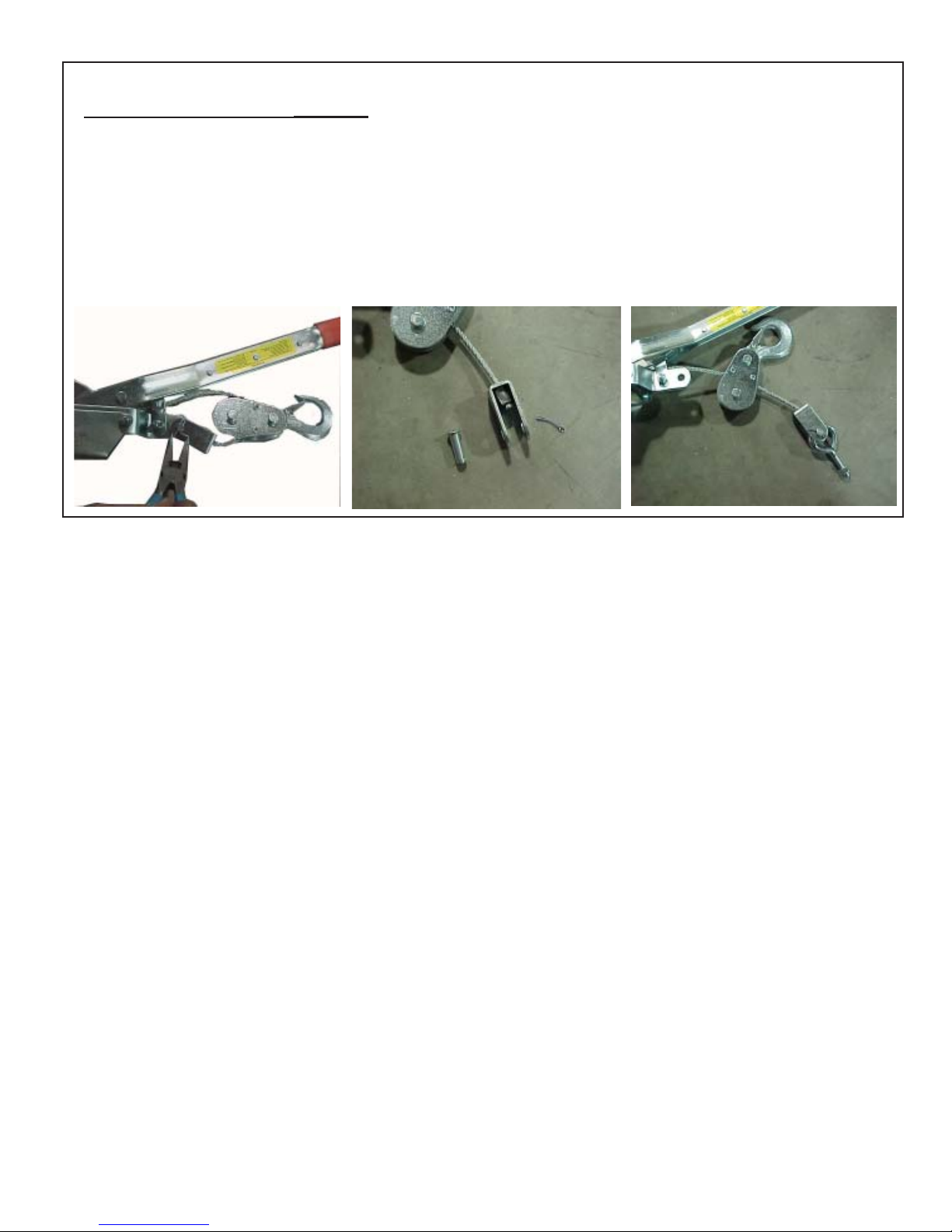
3Follow these instructions
very carefully for safe operation.
Test the whole system with 200 pounds or more of dead load
before attaching your top. Attach a weight or have a heavy
person hang from the hoist frame while you operate the hoist.
Do this a minimum of ten times--very important. This tests
the mechanism, the screw eyes in the wall and ceiling, and lets
you become familiar with the operation of the Cable Pulling
Mechanism. Try this several times, work it hard both up and
down to test everything, especially the ceiling mounting. For
instructions on operating the Cable Puller (1) see the pamphlet
inside the puller's shipping box .
Lifting Your Top
Helpful Hint: Fill an empty one-gallon milk carton about 3/4 full of
water. Slip the handle of the carton through the rear hook on the
empty hoist frame. This will balance your hoist so you can raise
it to the ceiling leveled (without top).
Lift the hoist to the ceiling and back your vehicle directly under
the hoist. (It may pay to mark a line on your garage floor to aid in
aligning your vehicle under the hoist). Open both doors.
Remove all attaching hardware holding your top and the light
plug/washer tube (if any). The hoist is not designed to lift your
Jeep, just the top. Position the frame as shown in Figure 8.
For all years of Jeep, an "L" rear hook is provided as standard
equipment at the back of the frame. Open the rear window and
slip the hook between the glass and the top. Turn the hook
under and position in the center of top.
Position the J Hooks under the edge at the front of the top (see
Figure 8). Remove and flip the two front sections of the top
and place on the frame of the hoist as shown in Figure 8. Note
that the sections are upside down with the "S" shape to the front.
Slide the top so that in back edge is nestled against the foam "T"
supports. Install the Stretch cords (15) as shown in Figure 8.
!!Caution!: Wear eye protection when using cords.
Crimping the back hook on the Stretch Cords will make securing
the top sections easier. Stretch the cords diagonally across the
top sections to the Eye Nuts (14) as shown in Figure 8. This
secures the top sections to the hoist. Having a friend help you
with the next operation will be helpful!!
Make sure the hoist is set to lift. See instructions in the Cable
Puller Box for lifting and lowering settings for the wire cable
puller. Lift your top off slowly a few inches. Use one hand on the
side to balance the top until it clears the vehicle body. Make
sure the top balances so that it remains fairly level when in the
stored position (Hanging slightly lower at the back will aid in
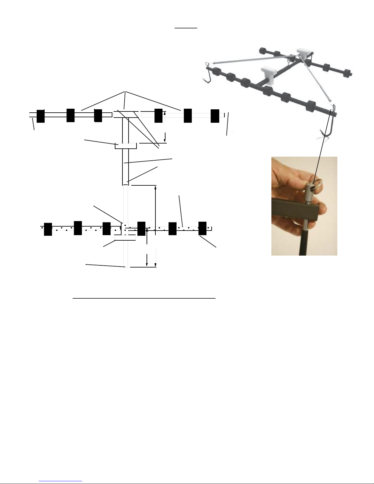
installation). To change the balance, move the Balance Slide,
see Figure 5 (either to the front of the jeep to lower the rear or to
the rear of the jeep to lower the front). Make sure you replace
the top back on the vehicle before moving the slide. When
the balance point is found, tighten the eyebolt until it presses
hard into the rear support bar, then tighten the safety lock nut to
additionally secure the eyebolt. Lift your top slowly a few inches
and recheck everything.
!CAUTION!: When lifting, keep fingers and arms away from
the underside of your top. Remember that all lift mecha-
nisms can fail without warning! Keep children and pets away
from the mechanism and out from under the top when stored
on the lift.
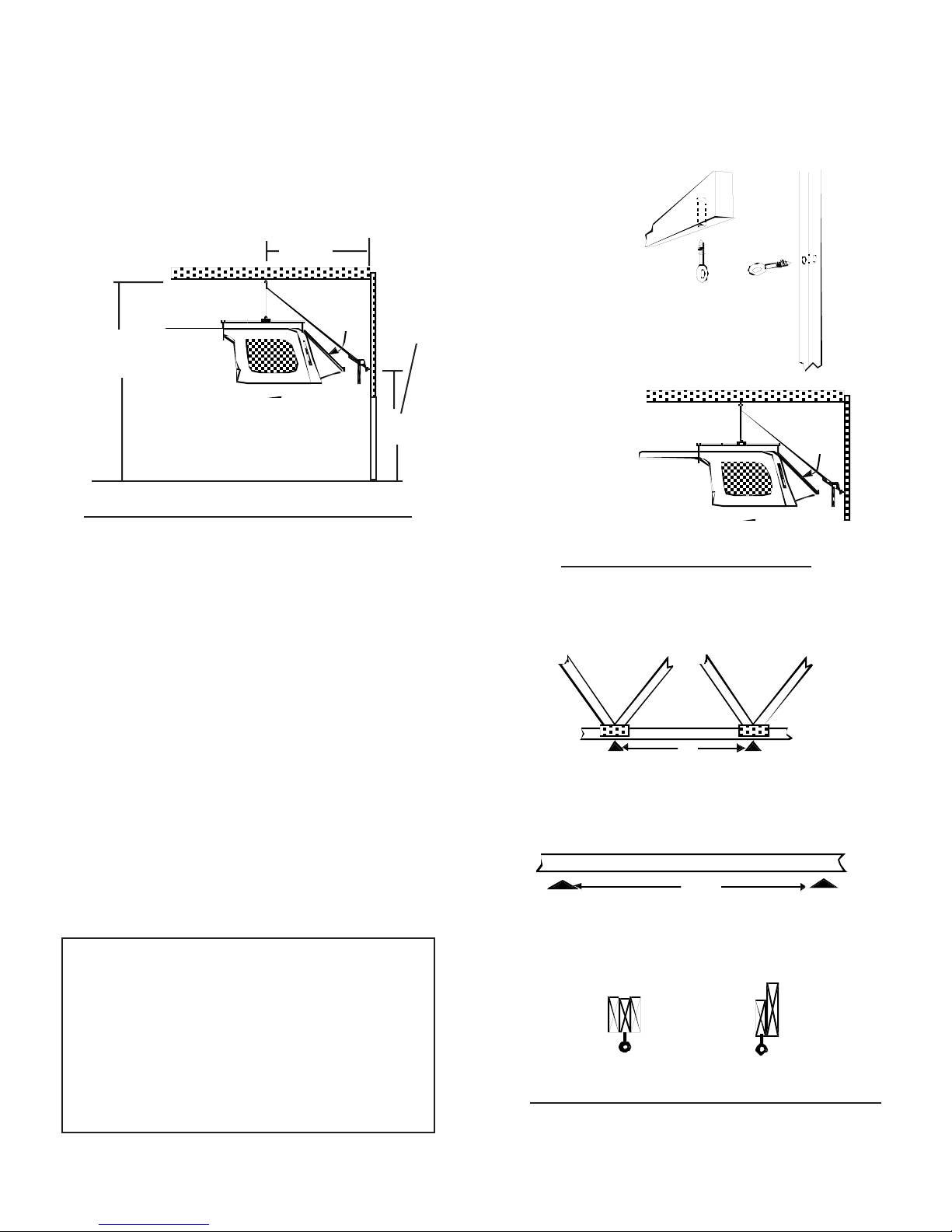
Figure 6 Foam "T"
Installation
Note, that the foam is shaped slightly differently in the
profile below. The highest side of the "T" goes on the
passengerside asshowbelow.
Front
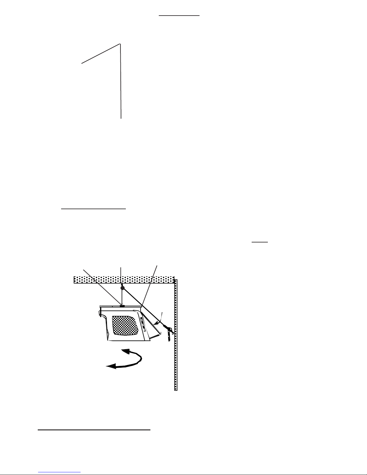
Using the Hoist-a-Top
Figure 7, Mounting Connections
After lifting your top, you
findthatthereis not enough
room for the rear window to
clear the hoist cable, rotate
the top 90 degrees and
leave the window up or
close partiallyand secure
with a cord. Optional tape
or cord holds window
closed(onlyclose half way
or you will break the
window). Exercise care in
closing window with the
hook in place to prevent
damage to window. We
don'trecommendclosing
the window! !Caution!
Keep the cable and other
objects clear of the window
glass or it may break.
RearL-Hookslips
betweentheglass and
the top
Move the slide to
adjust the balance of
the top if required.
You may rotate the top
after lifting to facilitate
ease of storage
Hookthepulley
onthepuller
cableintothe
ceilingeyebolt
Closehalf
way is
optional
4-Door JK Sheet 4