LANGER EMV-Technik OB 100 set User manual

2020.12.04 OB 100 set User manual
User Manual
OB 100 set
Opto-Box 100 LIN / CAN
Copyright (C) Dipl.- Ing. Gunter Langer
Nöthnitzer Hang 31
01728 Bannewitz
January 2020
Transmission of LIN signals and high-speed CAN signals via fiber optics

2
LANGER
EMV-Technik
DE-01728 Bannewitz
mail@langer-emv.de
www.langer-emv.com
OB 100 set
Content:............................................................................................................. Page
1. Declaration of Conformity...........................................................................................3
2. General Information.....................................................................................................4
2.1. Storing the User Manual..........................................................................................................4
2.2. Reading and Understanding the Manual.................................................................................4
2.3. Local Safety and Accident Prevention Regulations ................................................................4
2.4. Images......................................................................................................................................4
2.5. Limitations of Liability...............................................................................................................4
2.6. Errors and Omissions ..............................................................................................................4
2.7. Copyright..................................................................................................................................4
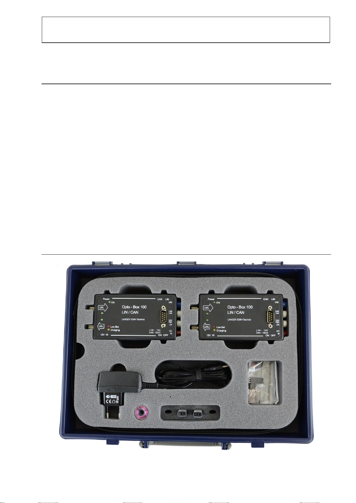
3. Scope of Delivery.........................................................................................................5
4. Technical Parameters..................................................................................................6
4.1. OB 100 - Opto-Box 100 ...........................................................................................................6
4.2. CAN 100 - Optical Fiber Probe................................................................................................6
4.3. LIN 100 - Optical Fiber Probe..................................................................................................6
5. Safety Instructions.......................................................................................................7
6. Information on Recycling and Disposal .....................................................................8
7. Application ...................................................................................................................9
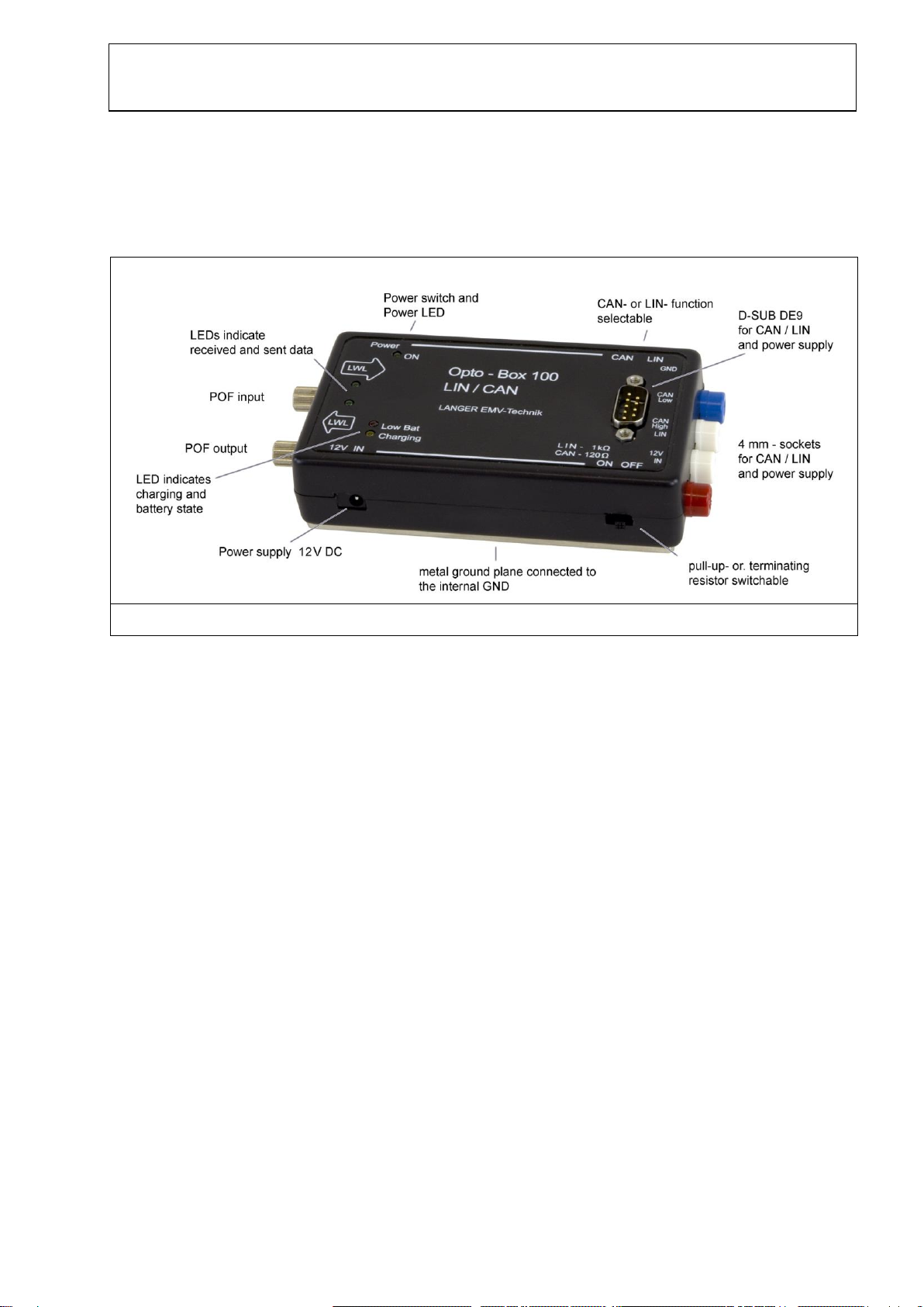
8. Design of Opto-Box 100.............................................................................................10
8.1. Mechanical Design.................................................................................................................10
8.2. GND Connection....................................................................................................................10
8.3. Voltage Supply.......................................................................................................................11
8.4. Signal Transmission –Electrical Connection........................................................................12
8.5. Signal Transmission –Optical Connection............................................................................13
9. Use of Opto-Box 100..................................................................................................14
9.1. Measurements according to Standards.................................................................................14
9.2. Measurements during Development......................................................................................15
10. CAN 100 / LIN 100 Sensors...................................................................................16
10.1.Mechanical Design.................................................................................................................16
10.2.Optical Connection.................................................................................................................16
10.3.Electrical Connection.............................................................................................................17
11. Warranty.................................................................................................................18
12. Customer Service..................................................................................................19

3
LANGER
EMV-Technik
DE-01728 Bannewitz
mail@langer-emv.de
www.langer-emv.com
OB 100 set
1. Declaration of Conformity
Manufacturer:
Langer EMV-Technik GmbH
Nöthnitzer Hang 31
01728 Bannewitz
Germany
Langer EMV-Technik GmbH hereby affirms, that the product specified below
OB 100 set, Opto-Box LIN / CAN
with Opto-Box 100, LIN 100 and CAN 100
agrees with the regulations of EC guidelines:
- EMC Directive 2014/30/EU
- Restriction of certain Hazardous Substances 2011/65/EU
Applied standards and technical specifications:
- DIN EN 61000-6-3:2011-09 EMC - Emission
- DIN EN 61000-6-1:2007-10 EMC - Immunity
- DIN EN 50581:2013-02 (Restrictions of hazardous substances)
Person authorized to compile the technical file:
Gunter Langer
Bannewitz, 12.01.2020
_________________
(Signature)
G. Langer, Executive Director

4
LANGER
EMV-Technik
DE-01728 Bannewitz
mail@langer-emv.de
www.langer-emv.com
OB 100 set
2. General Information
2.1. Storing the User Manual
This user manual provides the basis for the safe and efficient use of the OB 100 set. It must be
kept handy and easily accessible for the user.
2.2. Reading and Understanding the Manual
Read and understand the manual and observe the instructions carefully before using the
OB 100 set. Please consult Langer EMV-Technik GmbH if you have any questions or comments.
The user manual must be kept readily available in the immediate vicinity of the product.
2.3. Local Safety and Accident Prevention Regulations
The applicable local general safety and accident prevention regulations must be adhered to.
2.4. Images
Images in this manual facilitate a better understanding, but can deviate from the actual execution.
2.5. Limitations of Liability
The Langer EMV-Technik GmbH is not liable for personal injury or damage to material, if
- the instructions in this user manual were not followed,
- the product was used by personnel who are not qualified in the field of EMC and who are not fit to
work under the influence of disturbance voltages and electric and magnetic fields,
- the product was not used as intended,
- the product was arbitrarily modified or technically altered,
- spare parts or accessories were used, that were not authorized by Langer EMV-Technik GmbH.
The actual scope of delivery can deviate from the texts and images in this manual in the case of
individual adjustments to the order or recent technical changes.
2.6. Errors and Omissions
The information in this user manual has been checked very carefully and found to be correct to the
best of our knowledge; however, Langer EMV-Technik GmbH can assume no responsibility for
spelling, typographical or proofreading errors.
2.7. Copyright
The content of this user manual is protected by copyright and may only be used in connection with
the OB 100 set. This user manual may not be used for other purposes without the prior consent of
Langer EMV-Technik GmbH.

5
LANGER
EMV-Technik
DE-01728 Bannewitz
mail@langer-emv.de
www.langer-emv.com
OB 100 set
3. Scope of Delivery
Item Designation Type Qty.
01 Opto-Box 100 OB 100 2
02 Optical Fiber, Double LWL double 10 m 1
03 Optical Fiber Probe LIN 100 1
04 Optical Fiber Probe CAN 100 1
05 Adapter Socket 3-pole 4
06 Adapter Socket 4-pole 4
07 Enamelled Copper Wire Wire-CuL 1
08 Power Supply Unit NT Ex EU 1
09 System Case (240 x 190 x 55) mm 1
10 Quick Guide 1
11 User Manual 1

6
LANGER
EMV-Technik
DE-01728 Bannewitz
mail@langer-emv.de
www.langer-emv.com
OB 100 set
4. Technical Parameters
4.1. OB 100 - Opto-Box 100
Sizes (L x W x H)
(135 x 32 x 28) mm
Supply voltage
12 Volt (max. 25 Volt)
Max. current input at 12 V
250 mA mit Laden der internen Akkus
45 mA ohne Laden der internen Akkus
Operating time with charged internal
battery
(4 x AA with 2400 mAh)
Up to 1 week
depending on operating mode
ESD resistance
+/- 25 kV air and contact discharge
Optical fiber connection
2 x 2.2 mm Ø
Max. optical fiber length
20 m (6 m at 1 Mbit/s CAN)
4.2. CAN 100 - Optical Fiber Probe
Sizes (L x W x H) (with connector)
(37 x 12 x 8) mm
Supply voltage
4.5 ... 7.0 Volt
Dielectric strength
+/- 15 V
Current input
Approx. 40 mA (recessive)
max. approx. 80 mA (master, receive, dominant)
Max. transmission rate
1 Mbit/s
CAN transceiver
SN65HVD251
Optical fiber connection
2 x 2.2 mm Ø
Max. optical fiber length
10 m (6 m at 1 Mbit/s)
4.3. LIN 100 - Optical Fiber Probe
Sizes (L x W x H) (with connector)
(37 x 12 x 8) mm
Supply voltage
8 ... 15 Volt (as Master)
8 ... 30 Volt (as Slave)
Dielectric strength
+/- 40 V
Current input
approx. 40 mA (recessive)
max. approx. 80 mA (master, receive, dominant)
Max. transmission rate
20 kbps
Optical fiber connection
2 x 2.2 mm Ø
Max. optical fiber length
20 m

7
LANGER
EMV-Technik
DE-01728 Bannewitz
mail@langer-emv.de
www.langer-emv.com
OB 100 set
5. Safety Instructions
When using a product from Langer EMV-Technik GmbH, please observe the following safety
instructions to protect yourself against electric shock or the risk of injury.
Before each use, check externally for damage.
Damaged or defective devices are not to be used.
The operating and safety instructions for all devices included in the measurement set-up must
be observed.
The use of the devices under the influence of interference is to be carried out by personnel who
are experts in the field of EMC.
All devices are to be connected or disconnected only when the source of interference is
switched off.

8
LANGER
EMV-Technik
DE-01728 Bannewitz
mail@langer-emv.de
www.langer-emv.com
OB 100 set
6. Information on Recycling and Disposal
Waste Electrical and Electronic Equipment (WEEE) Directive (European Union):
At the end of its useful life, this product should be taken to an appropriate
disposal facility for recycling and disposal. Do not dispose of with household
waste.
Recyclable Products:
This product contains rechargeable batteries.
Please recycle used batteries at the end of their useful life or dispose of them
safely and properly. Many cities collect used batteries for recycling or disposal.
Please contact your local waste disposal office for information on battery
recycling and disposal.

9
LANGER
EMV-Technik
DE-01728 Bannewitz
mail@langer-emv.de
www.langer-emv.com
OB 100 set
7. Application
An Opto-Box 100 converts electrical CAN or LIN signals into optical signals. The use of two Opto-
Box 100 provides a simple possibility to cut an already existing cable connection and to replace a
section of the cable - without further configuration effort - by an optical fiber connection.
It is also possible to combine an Opto-Box 100 with a LIN 100 or CAN 100 sensor. The respective
sensor should be used directly on the DUT's circuit board. In this way, the CAN or LIN cable can
be completely replaced by a optic fiber cable for measurements during development within the test
hall/screening cabin, thus achieving a very high interference immunity of the signal connection. At
the same time, the interference decoupling from the signal cable is omitted.
Preferably, one Opto-Box 100 is used directly on the higher-level computer and communicates to a
second Opto-Box 100 or a LIN or CAN sensor close to the DUT - e.g. inside a measuring cabin.

10
LANGER
EMV-Technik
DE-01728 Bannewitz
mail@langer-emv.de
www.langer-emv.com
OB 100 set
8. Design of Opto-Box 100
8.1. Mechanical Design
All connection options and switches are shown in Figure 1.
Figure 1: Operating elements of the Opto-Box 100
8.2. GND Connection
The Opto-Box has a solid metal plate on the bottom side, which is galvanically connected several
times to the internal GND.
If the Opto-Box 100 is used in the context of interference immunity tests, it should be operated
isolated from the rest of the set-up in order to achieve the highest possible interference immunity of
the signal transmission. Many standards require this set-up anyway. For this purpose, the Opto-
Box must be placed isolated - if possible with a distance of a few centimeters - above the
frequently conductive substrate of the measurement set-up.
For measurements during development, however, it may be useful to connect the DUT and the
Opto-Box to a conductive substrate in order to reduce RF coupling in or out. In this case, it is
sufficient to simply place the Opto-Box on the conductive substrate (Figure 2).

11
LANGER
EMV-Technik
DE-01728 Bannewitz
mail@langer-emv.de
www.langer-emv.com
OB 100 set
Figure 2: Opto-Box 100 in LIN mode, measurement set-up for measurement during development
8.3. Voltage Supply
There are 4 possibilities to supply the Opto-Box 100 with voltage. In detail these are:
a) The DC8 socket marked 12V IN at the lower left edge of the device.
The supplied external plug-in power supply can be connected here. This operating mode
should be used if the Opto-Box 100 is operated outside the measuring hall/measuring
booth. The Opto-Box 100 is supplied via the power supply unit and the
internal batteries are charged at the same time.
b) PIN 9 (12V IN) and PIN 6 or PIN 3 (GND) of the D-SUB connector on the top of the device.
c) The build-in rechargeable batteries.
The Opto-Box 100 contains 4 commercially available NiMh batteries of type AA, which supply the
Opto-Box if no other voltage is applied. The state of charge is monitored. If the voltage drops below
4.7 V, the red LED "Low Bat" lights up.
If the Opto-Box 100 is supplied via a plug-in power supply unit at the DC8 socket, the batteries are
charged independently of the operating state of the Opto-Box. The yellow "Charging" LED lights
up. When the charging end voltage is reached, charging is interrupted and the "Charging" LED is
switched off. The batteries can remain in the device.
Note: The rechargeable batteries are only charged during operation via plug-in power
supply, but not during operation at 12 V via D-SUB plug or via laboratory plug.
The set charging current corresponds to approximately three times the maximum operating current
in battery mode. When using two Opto-Boxes in pairs inside and outside the measuring
hall/measuring booth, it is thus possible to exchange the Opto-Boxes at any time if one Opto-Box is
discharged and the second Opto-Box is permanently operated via plug-in power supply.
The built-in rechargeable batteries can be replaced. To do this, the Opto-Box must be switched off
and the two screws in the middle on the underside of the unit must be unscrewed (Figure 3). After
removing the upper part of the housing, the batteries are accessible.

12
LANGER
EMV-Technik
DE-01728 Bannewitz
mail@langer-emv.de
www.langer-emv.com
OB 100 set
Only 4 NiMh batteries (no fire risk) of the same type AA may be used in the Opto-Box. It is possible
to operate the Opto-Box 100 without internal batteries. However, when supplied via the DC8
socket, the "Low Bat" LED flashes during operation, indicating that no battery can be charged.
Figure 3: Bottom side of Opto-Box 100
8.4. Signal Transmission –Electrical Connection
Figure 4: Pin assignment of D-Sub socket
The LIN/CAN switch must first be used to select the operating mode.
In CAN mode, at least both CAN pins must be connected to the CAN signal of the DUT. If required,
an internal 120 Ohm terminating resistor (in CAN mode) can be connected via the "LIN / CAN ON
OFF" switch.
In LIN mode, at least the signal line and the ground are connected. If required, an internal 1 kOhm
pull-up resistor (LIN operation) can be connected for the "Master" operating mode via the
"LIN / CAN ON OFF" switch. If the Opto-Box 100 is operated via laboratory plug or D sub-
connector at approx. 12 V, the resistor connects the signal to this voltage. In battery operation, a
12 V voltage is generated internally and the LIN signal is connected to it via the resistor.
To open the housing,
loosen these screws!

13
LANGER
EMV-Technik
DE-01728 Bannewitz
mail@langer-emv.de
www.langer-emv.com
OB 100 set
8.5. Signal Transmission –Optical Connection
The double optical fiber is plugged into the optical fiber input and the optical fiber output (Figure 1)
and fixed with both knurled nuts. The ends of the two individual optical fibers are cut to different
lengths and can thus be correctly assigned:
The slightly longer optical fiber is always connected to the optical input, the slightly shorter one
to the optical output (see marking on the Opto-Box 100, long and short arrow).
The maximum length of the optical fiber is 20 m. In practice, however, in CAN operation at a
transmission rate of 1 Mbit/s, the delay of the optical receivers results in a reduction of the
permissible length to 6-10 m (depending on the edge steepness of the signal and the reaction time
of the other connected CAN nodes), since otherwise the acknowledge bit is no longer recognized
in time by the transmitter.
If the Opto-Box 100 is only used for "listening" to an existing CAN connection between other
nodes, this restriction does not exist.

14
LANGER
EMV-Technik
DE-01728 Bannewitz
mail@langer-emv.de
www.langer-emv.com
OB 100 set
9. Use of Opto-Box 100
9.1. Measurements according to Standards
To decouple LIN or CAN lines during EMC measurements in a measuring booth or an anechoic
chamber, two Opto-Boxes can be connected to each other via optical fibers (Fig. 5). The Opto-Box
located outside the hall should be permanently supplied via plug-in power supply. Its batteries are
thus also charged during operation. If the batteries of the Opto-Box inside the hall are discharged,
the Opto-Boxes can be exchanged at any time and the measurements can be continued.
Figure 5: Two Opto-Boxes for data transmission connected via fiber optics
To improve the EMC properties, we recommend (as specified in various standards anyway) that
the opto-box used inside the hall on the DUT be operated in isolation with a distance of a few
centimeters from any metallic base surface of the test setup (Figure 6).
Figure 6: Opto-Box 100 operated isolated

15
LANGER
EMV-Technik
DE-01728 Bannewitz
mail@langer-emv.de
www.langer-emv.com
OB 100 set
9.2. Measurements during Development
During development, it can be helpful to perform disturbance emission or disturbance immunity
measurements without LIN or CAN lines connected - for example, to determine whether the
functional error during coupling directly affects a CAN signal and a subsequent error occurs, or
whether coupling into another structure of the DUT causes the error.
If a signal connection is required to control or monitor the DUT in this case, it is necessary to use a
CAN 100 or LIN 100 sensor in conjunction with an Opto-Box (Figure 7). If the sensor is used as
described in section 10.3, it is possible to communicate with the DUT without any metallic signal
line.
Figure 7: One sensor with one Opto-Box for data transmission without LIN/CAN bus cable
In order to prevent the propagation of interference pulses via the signal lines when performing
immunity tests during development, e.g. with ESD or burst, the Opto-Box can be used for galvanic
isolation. If the test set-up is implemented with the aid of a metal surface, the Opto-Box can also be
connected to the metal surface as in Figure 8.
Figure 8: Opto-Box connected with metal surface

16
LANGER
EMV-Technik
DE-01728 Bannewitz
mail@langer-emv.de
www.langer-emv.com
OB 100 set
10. CAN 100 / LIN 100 Sensors
10.1. Mechanical Design
The CAN 100 and LIN 100 sensors are pluggable and have a GND, a supply and a CAN or LIN
connection. The optical connection is designed for a 2.2 mm double plastic optical fiber (pluggable)
(Figure 9 and Figure 10).
Figure 9: Connections on CAN 100
Figure 10: Connections on LIN 100
10.2. Optical Connection
The double fiber optic cable is simply plugged into the CAN 100 / LIN 100.
At both ends, the two individual optical fibers are cut to different lengths and thus assigned to the
correct opening on the CAN 100: The slightly longer optical fiber is always connected to the optical
input (long arrow), the slightly shorter one to the optical output (short arrow) (Figure 11). The
longer optical waveguide must also be pushed further into the CAN 100 (up to the stop), so that
when correctly connected, the double optical waveguide is just connected to the
CAN 100 / LIN 100.
The maximum length of the optical fiber is 20 m.
Figure 11: Connection CAN 100 with the optical fiber
Attention with CAN 100 and 1 MHz transmission rate:
At a transmission rate of 1 Mbit/s, however, the delay of the optical receivers limits the possible
However, the delay of the optical receivers limits the possible length (depending on the edge
steepness and response time of the other connected CAN nodes) to less than 20 m.
If the CAN 100 is only used to "listen in" on an existing CAN connection between other nodes,
there is no such limitation.

17
LANGER
EMV-Technik
DE-01728 Bannewitz
mail@langer-emv.de
www.langer-emv.com
OB 100 set
10.3. Electrical Connection
The CAN 100 is supplied with GND and +5 V supply voltage from the electronics module. If the
supply voltage rises above approx. 7 V, the CAN 100 switches off to avoid overheating. Both CAN
pins are connected to the CAN signal of the electronics. If required, an internal 120 Ohm terminat-
ing resistor can be connected via the switch on the CAN 100.
The edge steepness of the signals output by the CAN 100 can be changed with a screwdriver.
Depending on the transmission rate, a minimum edge steepness is required; at a transmission rate
of 1 Mbit/s, the setting control must be set to "fast" (delivery state).
The LIN 100 is supplied with GND and supply voltage from the electronics module, the LIN pin is
connected to the LIN signal of the electronics. Via the switch at the LIN 100 an internal 1 kOhm
pull-up resistor can be connected if required (for operation as master).
With a screwdriver the edge steepness of the signals output by the LIN 100 can be changed.
Depending on the transmission rate, a minimum edge steepness is required, at 20 kHz
transmission rate the setting control must be set to "fast" (delivery state).
Note: To measure error-free under RF irradiation, burst or ESD, the CAN 100 must be
connected to the DUT for a very short time.
Probe tips of the usual type are too large. For a correspondingly small-scale setup, it is recom-
mended to solder the CAN 100 directly into the module via an adapter socket (included in the
scope of delivery). For this purpose, the socket is glued onto the PCB or an IC of the DUT (with
superglue or double-sided adhesive tape) and briefly connected to the DUT with CuL wire accord-
ing to the pin assignment (Fig. 12).
Hint:
The closer the CAN 100 / LIN 100 is
arranged with its housing to the GND
system of the DUT and the shorter
the GND connection to the module,
the greater the interference immunity
of the set-up.
Figure 12: CAN 100 optimally used

18
LANGER
EMV-Technik
DE-01728 Bannewitz
mail@langer-emv.de
www.langer-emv.com
OB 100 set
11. Warranty
Langer EMV-Technik GmbH will remedy any fault due to defective material or defective
manufacture during the statutory warranty period either by repair or by delivery of spare
parts.
This warranty is only granted on condition that:
The information and instructions in the user manual have been observed.
The warranty will be forfeited if:
An unauthorized repair is performed on the product.
The product is modified.
The product is not used for its intended purpose.
The product is opened.

19
LANGER
EMV-Technik
DE-01728 Bannewitz
mail@langer-emv.de
www.langer-emv.com
OB 100 set
12. Customer Service
Please contact us if you have any queries, hints and suggestions.
You can reach us: Monday - Friday 8:00 am to 4:00 pm (CET)
Contact us at: Langer EMV-Technik GmbH
Rosentitzer Straße 73
01728 Bannewitz
Germany
Internet: https://www.langer-emv.com
E-mail: mail@langer-emv.de
Phone: +49 (0) 351-430093-0
Fax: +49 (0) 351-430093-22
This document may not be copied, reproduced or electronically processed, either in its
entirety or in part, without the prior written permission of Langer EMV-Technik GmbH.
The management of Langer EMV-Technik GmbH assumes no liability for damage that may arise from
using this printed information.
LANGER
Nöthnitzer Hang 31
Tel.: +49(0)351/430093-0
EMV-Technik GmbH
DE-01728 Bannewitz
Fax: +49(0)351/430093-22
www.langer-emv.com
mail@langer-emv.de
This manual suits for next models
4
Table of contents
Popular Media Converter manuals by other brands

Manhattan
Manhattan 207959 instructions

Star Cooperation
Star Cooperation FlexMedia 1000BASE-T1 Instructions for use

MRC
MRC 0001803 quick start guide

Grafisk Maskinfabrik
Grafisk Maskinfabrik DC330mini operating manual

Tektronix
Tektronix P6701B instructions

Littfinski Daten Technik
Littfinski Daten Technik SA-DEC-4-MM-B Assembly instruction

Omnitron Systems Technology
Omnitron Systems Technology iConverter CWDM/X user manual

Lika
Lika CANopen A 58 CB Series user guide

Cambridge Audio
Cambridge Audio DacMagic 200M manual

Vacon
Vacon NXL series user manual

Aurora Multimedia
Aurora Multimedia ASP-DTH user manual

Atlona
Atlona AT-LINE-PRO2 user manual