Novanta Celera Motion Optira Series User manual

MicroE Optira Installation Manual
Celera Motion
IM
-1001 | REV181211 Page i ©2018 Celera Motion

MicroE Optira Installation Manual Celera Motion
IM-1001 | REV181211 Page i ©2018 Celera Motion
1.0 Table of Contents
2.0 Introduction.......................................................................................................................................1
2.1 Overview .............................................................................................................................1
2.2 Precautions .........................................................................................................................1
2.3 Laser Safety Information .....................................................................................................1
2.4 Standards Compliance ........................................................................................................2
2.5 Related Documentation.......................................................................................................2
2.6 Trademarks .........................................................................................................................2
2.7 Special Conventions Used ..................................................................................................2
3.0 Before Installation.............................................................................................................................3
3.1 Power Recommendations ...................................................................................................3
3.2 Installation Considerations ..................................................................................................3
3.3 Items Required for Installation ............................................................................................3
3.4 Sensor Installation Flowchart ..............................................................................................4
4.0 System Overview .............................................................................................................................5
4.1 Top Mounting ......................................................................................................................5
4.2 Board-to-Board Mounting....................................................................................................6
4.3 Optional Development Kit ...................................................................................................7
4.4 Optional Connector and Calibration Board .........................................................................7
5.0 Design Mounting ..............................................................................................................................8
6.0 Sensor Installation............................................................................................................................8
6.1 Install Sensor.......................................................................................................................8
6.1.1 Sensor Mounting Orientation and Tolerances .......................................................9
6.1.2Top Mounting .........................................................................................................9
6.1.3 PCB Mounting ......................................................................................................11
6.1.4 Sensor Head Alignment .......................................................................................11
6.1.5 LSB Index Calibration ..........................................................................................12
6.2 Install Optional Connector and Calibration Board.............................................................14
7.0 Appendix ........................................................................................................................................15
7.1 Specifications ....................................................................................................................15
7.2 Power-Up Timing...............................................................................................................16
7.3 Sensor Connectors Pinouts ..............................................................................................16
7.4 Recommended Signal Termination...................................................................................17
7.5 Board-to-Board Header Wiring Examples.........................................................................18
7.6 Connector and Calibration Board Connector Pinouts .......................................................20
7.7 Customer Interface............................................................................................................21
7.8RS-422 Compatibility.........................................................................................................21
7.9 Troubleshooting.................................................................................................................21
8.0 Order Guide....................................................................................................................................22
9.0 Introduction to Scale Mounting.......................................................................................................23
9.1 Overview ...........................................................................................................................23
10.0 Rotary Scales .................................................................................................................................24
11.0 Tape Scale Installation ...................................................................................................................24
11.1 Before Installation..............................................................................................................24
11.1.1 Items Required for Tape Scale Installation ..........................................................24
11.1.2 Pre-Installation Information and Precautions .......................................................24
11.1.3 Flowchart for Tape Scale Installation ...................................................................26
11.1.4 Design Guide........................................................................................................27

MicroE Optira Installation Manual Celera Motion
IM-1001 | REV181211 Page ii ©2018 Celera Motion
11.1.5 Prepare Mounting Surface ...................................................................................28
11.2 Cutting Tape Scales ..........................................................................................................29
11.3 Install the Tape Scale........................................................................................................30
11.3.1 Install Tape Scale Manually .................................................................................30
11.3.2 Install Tape Scale Using the Applicator Tool .......................................................34
12.0 Linear Glass Scales Installation .....................................................................................................43
12.1 Before Installation..............................................................................................................43
12.1.1 Items Required for Glass Scale Installation .........................................................43
12.1.2 Flowchart for Glass Scale Installation ..................................................................43
12.2 Benching Linear Glass Scales ..........................................................................................44
12.3 Prepare Mounting Surface ................................................................................................44
12.4 Install Linear Glass Scales ................................................................................................44
13.0 Final Cleaning, Inspection, and Cure Time....................................................................................45
13.1 Reworking to Correct Mistakes .........................................................................................45
13.2 Cleaning Scales ................................................................................................................45
14.0 Contacting Celera Motion...............................................................................................................45
MicroE Optira Installation Manual Celera Motion
IM-1001 | REV181211 Page 1 ©2018 Celera Motion
2.0 Introduction
2.1 Overview
The instructions in this manual apply to the following Optira Series Encoders models:
•Model PIA Standard 5 V
•Model PIB Standard 3.3 V
2.2 Precautions
1. Follow standard ESD precautions. Turn power to off before connecting sensor.
2. Do not touch electrical pins without static protection such as a grounded wrist
strap.
2.3 Laser Safety Information
This product is sold solely for use as a component (or replacement) in an electronic product;
therefore, it is not required to, and does not comply with U.S. FDA 21 CFR 1040.10 and 1040.11
which pertain to complete laser products. The manufacturer of the complete system-level
electronic product is responsible for complying with 21 CFR.
MicroE Systems encoders contain an infrared laser diode or diodes. Emitted invisible laser
radiation levels have been measured to be within the CDRH Class 1 range, which is not
considered hazardous; however, to minimize exposure to the diverging beam, install the encoder
sensor in its operational configuration in close proximity to the encoder scale before
applying power.
•Invisible laser radiation; wavelength: 850 nm.
•Maximum power of 4.8 mW CW for Optira.
•Caution: The use of optical instruments with this product will increase eye hazard. Do
not view directly with optical instruments (microscopes, eye loupes, or magnifiers).
•All maintenance procedures such as cleaning must be performed with the MicroE
encoder turned off.
•Do not insert any reflective surface into the beam path when the encoder is powered.
•Do not attempt to service the MicroE encoder.
MicroE Optira Installation Manual Celera Motion
IM-1001 | REV181211 Page 2 ©2018 Celera Motion
2.4 Standards Compliance
Optira Series Encoders are RoHS, REACH, and CE compliant.
2.5 Related Documentation
•Optira Series Encoders Data Sheet
•Optira Series Encoders Interface Drawings
2.6 Trademarks
Optira trademark of Novanta Inc. d/b/a Celera Motion.
2.7 Special Conventions Used
The following symbols may be used in this document.
Symbol
Description
Warning or caution: potential damage to parts.
Instructions show correct method.
Instructions show example of incorrect method.
See Section 2.2 Single click with the mouse on these highlighted references
to jump to specified places in instructions.

MicroE Optira Installation Manual Celera Motion
IM-1001 | REV181211 Page 3 ©2018 Celera Motion
3.0 Before Installation
Review the items in this section prior to installing the encoder.
3.1 Power Recommendations
Optira Series Encoders can be ordered with either 5 VDC or 3.3 VDC power supplies:
Power
Supply
Minimum
Input
Voltage
Maximum
Input
Voltage
Maximum
Current Draw
(Digital)
Maximum
Current Draw
(Analog)
Maximum
Current Draw
(No Load)
5.0 VDC
4.75 VDC
5.25 VDC
130 mA
100 mA
75 mA
3.3 VDC
3.13 VDC
3.46 VDC
130 mA
100 mA
75 mA
When designing circuits and extension cables to use Optira encoders, be sure to account for
voltage loss over distance and tolerances from the nominal supply voltage so that at least the
minimum continuous voltage is available to the Optira encoder under all operating conditions.
3.2 Installation Considerations
The Optira encoder is a precision electronic instrument. It has been designed to function in a wide
range of applications and environments. To take full advantage of the Optira design, allow easy
access to the sensor for service and/or replacement.
For optimal performance and reliability:
•DO follow standard ESD precautions while handling the sensor.
•DO allow proper clearance for sensor head alignment.
•DO follow setup and calibration instructions for the encoder system.
•DO, where possible, install the scales in an inverted or vertical position to minimize
accumulation of dust.
•DO NOT store sensors in an uncontrolled environment.
•DO NOT electrically overstress the sensor (power supply ripple/noise).
•DO NOT intentionally “hot swap” the sensor if the device is energized.
•DO NOT use in high contamination applications (dust, oil, excessive humidity, or other
airborne contaminants).
3.3 Items Required for Installation
In addition to the items identified in Section 3.0 System Overview,you will need the following
items available for installation:
Item
Z-Height shim1(0.020")
Screwdriver
Finger Cots or talc-free gloves
Acetone or isopropyl alcohol
Lint-free cotton cloths or wipes
Epoxy, non-conductive2
Stick and disposable surface for stirring epoxy2
Notes:
1. Part of optional Development Kit; not required if using a benching edge for installation.
2. Not required for all installations.
MicroE Optira Installation Manual Celera Motion
IM-1001 | REV181211 Page 4 ©2018 Celera Motion
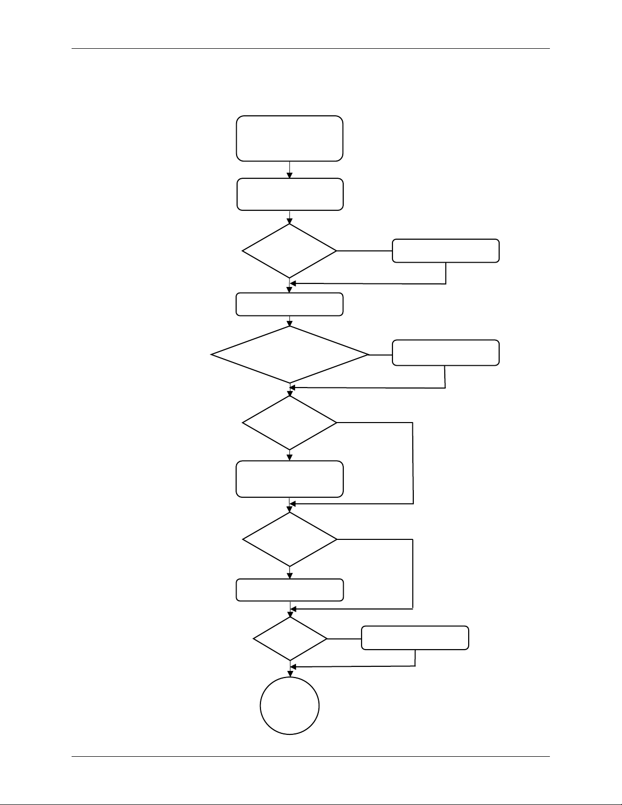
3.4 Sensor Installation Flowchart
The following flowchart shows the main steps in encoder installation, alignment, and calibration.
Design Mounting
Is Z-Height
adjustable?
Align Sensor
No
Yes
Set Z-Height
using shim
Benching
Edge?
Install
Complete
LSB?
Install Scale
Calibrate
Install Sensor
Yes
No
Yes
No
Optional Connection
and Calibration board? Install board
Yes
No
Install Flex
Cable? Attach Flex Cable
No
Yes
Section 4.0
Section 5.1.4
Section 5.0
Section 5.1.5
Section 5.0
Section 5.1
Section 5.2
Section 5.1.2
MicroE Optira Installation Manual Celera Motion
IM-1001 | REV181211 Page 5 ©2018 Celera Motion
4.0 System Overview
This section identifies parts for the Optira sensor installation. Use the information in this section to
design the mounting scheme for the sensor and the optional connector and calibration board.
Refer to the Optira Series Encoders Interface Drawings for details. Alignment not required when
benching sensor.
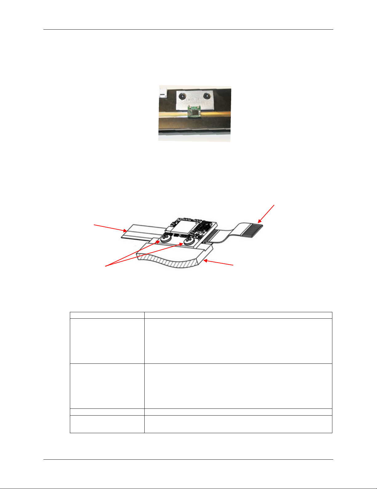
4.1 Top Mounting
This section contains information needed for installing the sensor in a top mount configuration.
The sensor can be mounted directly to customer’s bracket or equivalent surface using two
mounting screws.
Recommended Customer Required Parts
The following parts or their equivalents are recommended for the mechanical mounting of the
Optira sensor.
Item
Description
Mounting Screws (2)
M1.6 or 0-80 screws. Philips head screws are recommended. Do not use
slotted-head screws which can allow the screwdriver to slip and damage
components. Tighten screws per torque specification: 0.34Nm (3 inch-
lbs.) maximum.
Caution: Be careful tightening these screws to avoid damaging nearby
components.
FFC Cable
Flexible Flat Cable (FFC): 0.5 mm, Type 1, 10 P. Maximum length of 5 m.
J1 ZIF Connector is Hirose®FH33J-10S-0.5SH(10).
If long flex cables are needed, contact Selmark Associates for Parlex®
cables or contact another equivalent manufacturer.
Tip: For high mechanical stress environments, secure FFC to ZIF
connector using non-conductive epoxy.
ZIF Connector
Various FFC Connectors, Surface Mount, ZIF, 10 pins, .5 mm pitch.
Z-Height Shim Spacer
Shim for setting gap between sensor riser and top of installed scale. Not
needed for most installs. (Part of optional Development Kit)
Note: For scales, see Optira Series Encoders Tape and
Glass Scales Installation Manual.
Detachable FFC Cable
Mounting Screws
Tape Scale
Customer Provided Bracket
Sensor
Example of installed sensor
MicroE Optira Installation Manual Celera Motion
IM-1001 | REV181211 Page 6 ©2018 Celera Motion
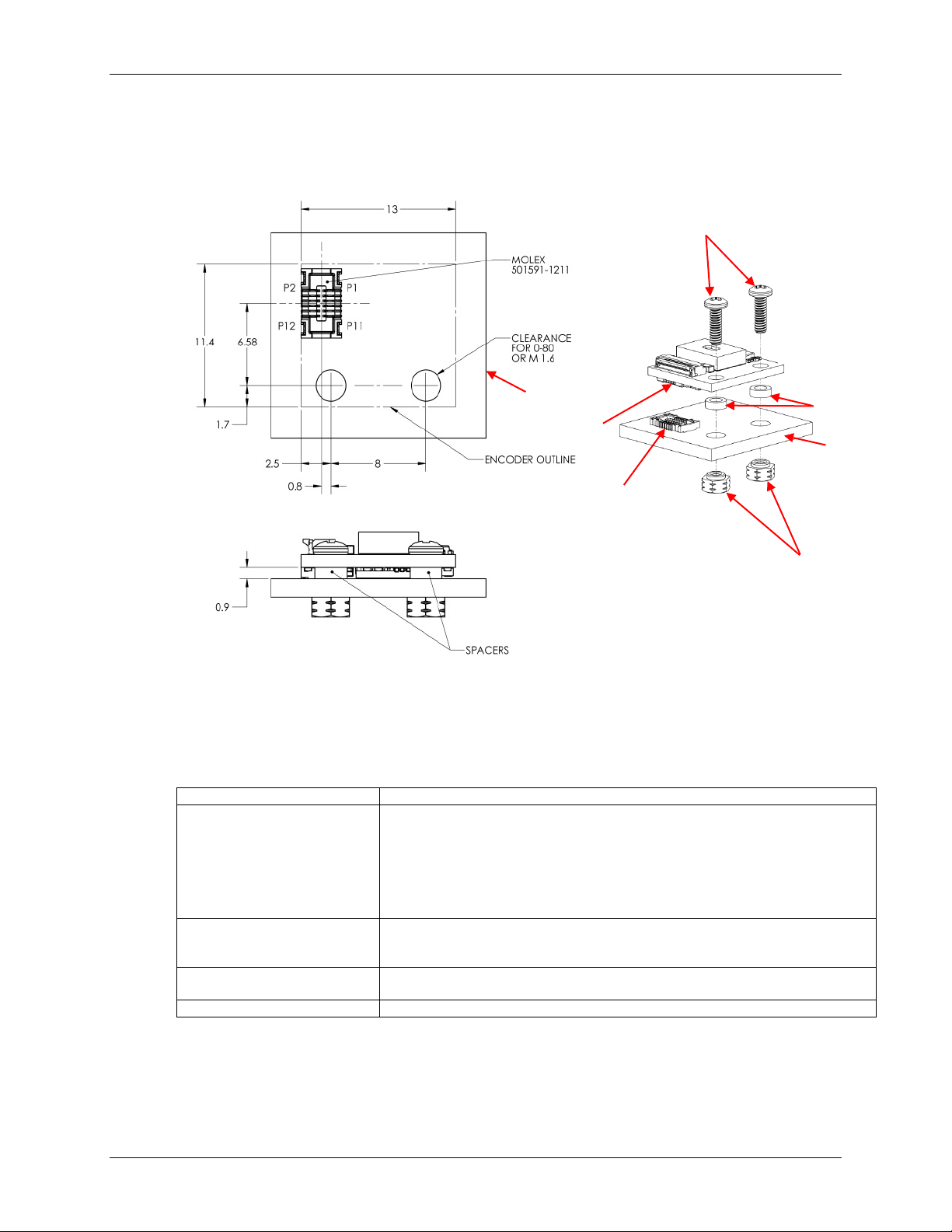
4.2 Board-to-Board Mounting
This section contains information needed for installing the Optira sensor to the customer's PCB.
Recommended Customer Required Parts
The following parts or their equivalents are recommended for the board-to-board mounting of the
Optira sensor.
Item
Description
Mounting Screws (2)
M1.6 or 0-80 screws. Philips head screws are recommended. Do not use
slotted-head screws which can cause the screwdriver to slip and damage
components. Tighten screws per torque specification: 0.34 Nm (3 inch-lbs.)
maximum.
Caution: Be careful tightening these screws to avoid damaging nearby
components.
PCB Mount Connector1
Molex
®
part number 501591-1211: 0.40 mm (.016") pitch board-to-board
vertical mating receptacle. Mates to JP1 board-to-board connector (Molex
part number 501594-1211) on sensor.
Spacers (2)
Diameter cannot exceed keep-out area of 3.17 mm (see sensor dimensions
on Optira Interface Drawing). Height is .9 mm.
Surface Mount Fasteners (2)
MicroPEM®Fasteners, Type is SMTSO .060-80 (#0-80) or equivalent.
Note1: Header Mating: The header mating connector has a limited durability of 20 mating cycles
maximum.
Customer Bracket
Molex 501591-1211
Molex 501594-1211
Screws
Surface Mount Fasteners
Sensor
Bottom View
Spacers
Customer
Bracket

MicroE Optira Installation Manual Celera Motion
IM-1001 | REV181211 Page 7 ©2018 Celera Motion
4.3 Optional Development Kit
The following are the components of the optional Development Kit model PI-DK:
Part
Description
Connector and
Calibration Board
Interface board located between the Optira sensor and the customer’s controller:
•Provides feedback of sensor operation to customer electronics
•Provides control for calibration and alignment
•Size: 0.591" x 0.886"
•No signal processing
200mm FFC Cable
Flat flexible cable (FFC) that connects sensor to optional interface board or
directly to customer electronics:
•Digikey 732-3556-ND
•Wurth Electronics®part number 687610200002 (0.5 mm, Type 1, 10P,
200 mm)
3m Controller Cable
Custom Development Kit Cable with JST®Connector and 15-Pin D-Sub to
connect between Connector and Calibration Board and customer’s electronics.
Z-Height Shim Spacer
Shim for setting gap between sensor riser and top of installed scale.
4.4 Optional Connector and Calibration Board
This section contains information needed to install the optional Connector and Calibration Board.
LED Configuration Switch S2
Switch
Description
On
Off
1
Red Alarm LED (D2)
Alarm is active low
Alarm is active high
2
Green Power On LED (D1)1
Power On LED is On
Power On LED is Off
Default from factory: both S1 and S2 are set to ON.
Note1:S2 is not a power switch; intended only to turn LED off for light sensitive applications.
LED Configuration Switch (S2)
Calibration
Pushbutton (S1)
Green Power On
LED (D1)
Red Alarm
LED (D2)
Connector J2
Connector J1
J1 Pin 1
Note: Protect the
mounting area with
insulating material.
(Mounting Holes)
MicroE Optira Installation Manual Celera Motion
IM-1001 | REV181211 Page 8 ©2018 Celera Motion
Recommended Customer Required Parts
The following parts or their equivalents are recommended for using the optional Connector and
Calibration board.
Item
Description
Custom Connector
Parts required to connect custom cable to header connector J2 (JST SM10B-
SRSS-TB):
•Mating Connector JST 10SR-3S
•Crimping Tool JST YRS-859
•Terminal Connector JST SSH-003T-P0.2 (28 – 32 AWG TIN)
Screwdriver
WiHa 26008. Small plastic screw driver to change settings on the DIP switch on
the Connector and Calibration Board.
FFC Cable
Flexible Flat Cable (FFC): 0.5 mm, Type 1, 10 P. Maximum length of 5 m.
Refer to manufacturer’s specification.
If long flex cables are needed, contact Selmark Associates for Parlex cables or
contact another equivalent manufacturer.
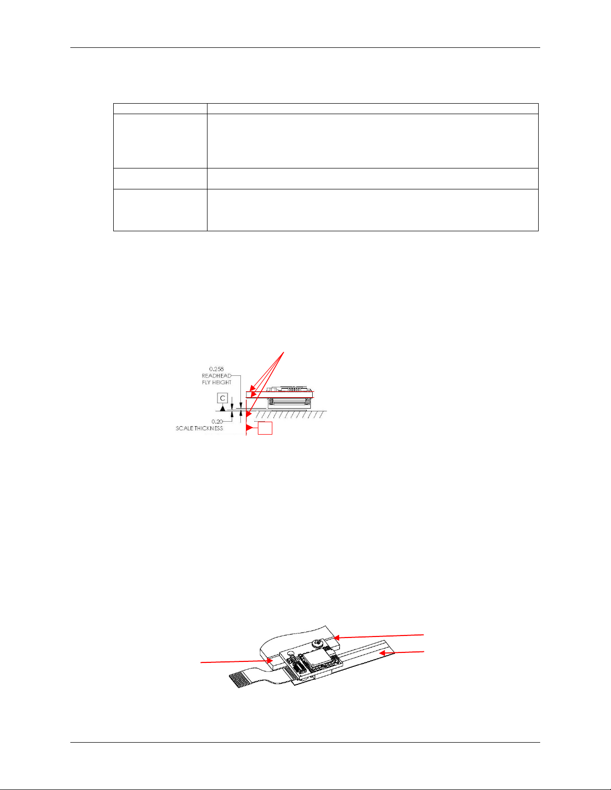
5.0 Design Mounting
This section contains instructions for designing the mounting scheme for installing the sensor. A
benching edge is recommended to locate the sensor to meet mechanical mounting tolerances.
Refer to the Interface Drawing for recommended location and height of edge. Use the following
reference surfaces for sensor installation.
6.0 Sensor Installation
This section contains instructions for installing the sensor and the optional connector and
calibration board.
6.1 Install Sensor
Note: Tape or glass scales must be installed before installing the sensor. Refer to the Optira
Tape and Glass Scales Installation Manual for instructions.
Refer to the Optira Interface Drawing ID-00400 for details for sensor installation. A benching edge
is recommended to locate the sensor to meet mechanical mounting tolerances. Refer to the
Interface Drawing for recommended location and height of edge.
Note: When installing sensor, ensure that the detector is always facing grating.
Mounting surface
Benching edge
Installed tape scale
Reference Surfaces
A
MicroE Optira Installation Manual Celera Motion
IM-1001 | REV181211 Page 9 ©2018 Celera Motion
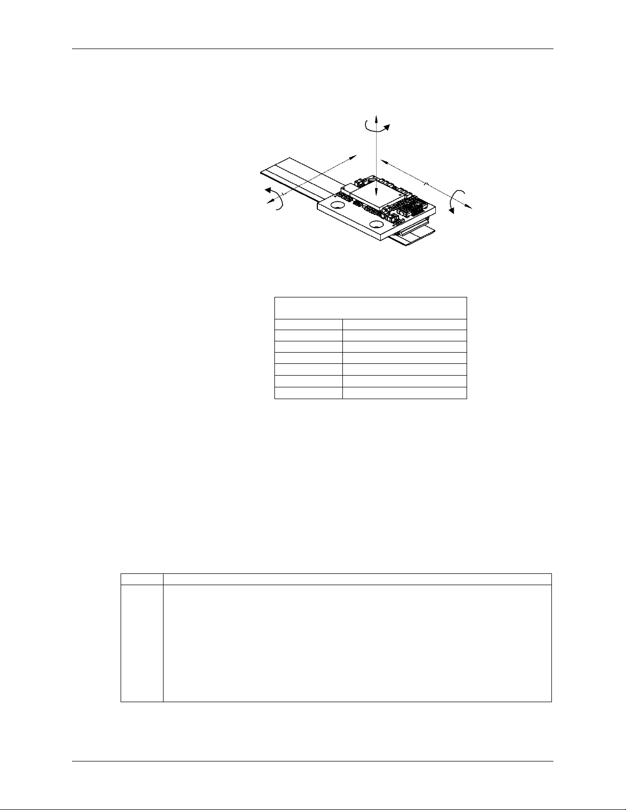
6.1.1 Sensor Mounting Orientation and Tolerances
Refer to the following specifications when installing and aligning the Optira sensor.
Orientation
Tolerances
Optira Series Encoders
Sensor Alignment Tolerances
Axis
Alignment Tolerance
X
Direction of Motion
Y
± 0.15 mm
Z
± 0.15 mm
θX
± 1.0°
θY
± 1.0°
θZ
± 2.0°
Note: Tolerance for each axis is specified independently, assuming nominal alignment in other
axes.
6.1.2 Top Mounting
Perform the following steps to install sensor. Benching the sensor is the preferred method for
installation and the sensor will then not require an alignment. Refer to sensor information in
Section 3.0 System Overview. For installing the sensor to a PCB, go to Section 5.1.3 PCB
Mounting.
Note: A scale must be installed before installing the sensor. Refer to the Optira Series
Encoders Tape and Glass Scales Installation Manual for instructions.
Step
Action
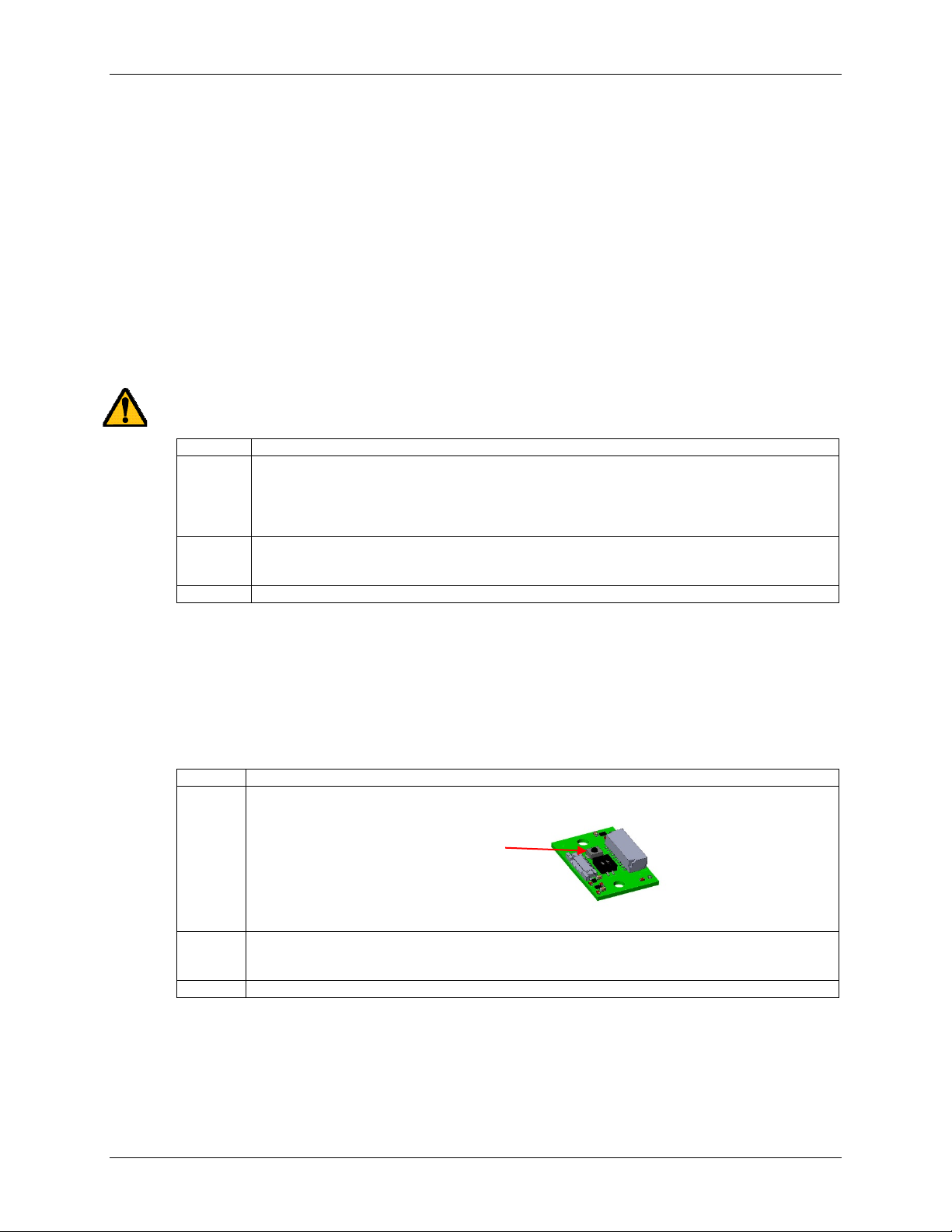
1.
Attach the FFC cable to the sensor ZIF connector J1 before installing sensor (see note
below about space restriction). Be careful when connecting/disconnecting the FFC to not
damage the connector.
Note: Once sensor is mounted, there is not sufficient space to safely disconnect or connect
the FFC cable. As there is limited clearance between the ZIF connector and the scale
surface, it is recommended that the FFC be mounted to the connector prior to
mounting the sensor.
Tip: For high mechanical stress environments, secure the FFC to ZIF connector using
non-conductive epoxy.
ϴZ
ϴY
ϴX
Z
X
Y
Sensor Axes

MicroE Optira Installation Manual Celera Motion
IM-1001 | REV181211 Page 10 ©2018 Celera Motion
Step
Action
2.
Z-Height:
If Z-Height is not adjustable, firmly place sensor against benching edge.
If Z-Height is adjustable, go to Step 5.
3.
Use two M1.6 or 0-80 screws to attach the sensor and tighten per torque specification:
0.34Nm
(3 inch-lbs.) maximum.
4.
Connect sensor to customer’s electronics or to the optional Connector and Calibration
Board.
Result: Sensor installation is complete for benching install. Alignment not required with
benching installation. If sensor has an LSB index, go to Section 5.1.5 LSB Index
Calibration.
5.
If Z-Height is adjustable:
Use the Z-Height Shim Spacer (part of optional development kit) to set the proper gap
between the sensor’s riser and the top of the scale (0.493 mm). Refer to the Optira Interface
Drawing for details.
6.
Insert the Z-Height Shim Spacer between the sensor’s riser and the top of the scale.
7.
Fully tighten the two M1.6 or 0-80 screws to attach the sensor. Tighten screws per torque
specification: 0.34Nm (3 inch-lbs.) maximum. Adjust the Z-Height. The shim should move
with minimal friction between the riser and the scale. Remove shim.
8.
Connect sensor to customer’s electronics or to the optional Connector and Calibration
Board.
Result: Sensor installation is complete for adjustable Z-Height install.
Note: If sensor was not installed using benching, then go to Section 5.1.4 Sensor Head
Alignment Sensor Head Alignment to align the sensor.
Z-Height Shim Spacer
Side View of Sensor
Riser
Installed tape scale
Side View of Sensor
Insert the shim here between
bottom of riser and top of the
installed tape scale
Installed tape scale
Riser
Z-Height Shim Spacer
Benching edge
MicroE Optira Installation Manual Celera Motion
IM-1001 | REV181211 Page 11 ©2018 Celera Motion
6.1.3 PCB Mounting
Perform the following steps to mount sensor to customer's PCB. Refer to sensor information in
Section 3.0 System Overview.
Note: A scale must be installed before installing the sensor. Refer to the Optira Series
Encoders Tape and Glass Scales Installation Manual.
Step
Action
1.
Use spacers to maintain sufficient space between sensor and PCB.
2.
Press sensor to PCB carefully ensuring good connection for mating connectors.
3.
Insert mounting screws between sensor and PCB through spacers.
4.
Attach surface mount fasteners securely.
5.
Install the PCB on the mounting surface referencing the appropriate datum surface as
shown in the Optira Interface Drawing. Use two M1.6 or 0-80 screws and tighten per torque
specification: 0.34Nm (3 inch-lbs.) maximum.
6.
Connect PCB to customer’s electronics or to the optional Connector and Calibration Board.
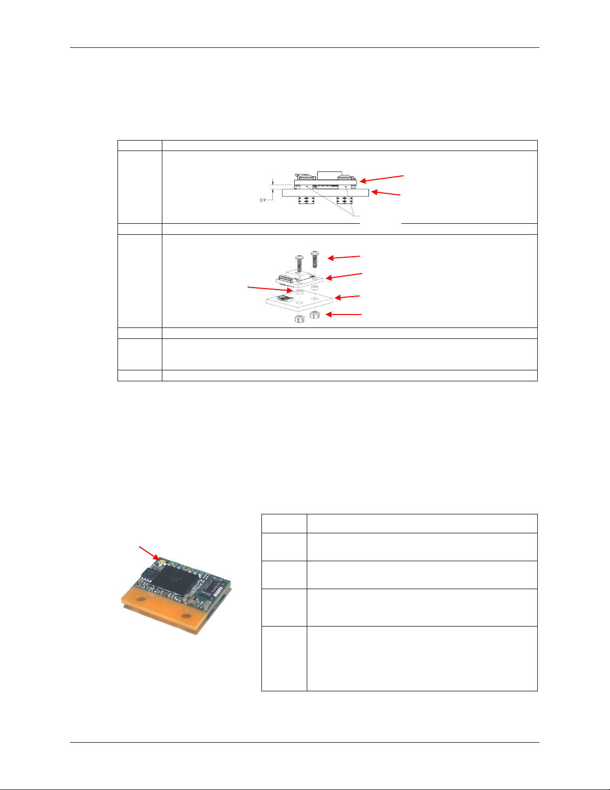
6.1.4 Sensor Head Alignment
6.1.4.1 Status LED Version A (Standard)
Alignment is positioning of the sensor with respect to the scale to achieve proper signal strength
from the count track and the index track. Proper sensor alignment may require minor adjustments
to the sensor position with respect to the scale.
Sensor alignment can be performed easily by using the sensor’s Status LED indicator, which
lights depending on sensor alignment as follows:
Note1: The Status LED can be ordered with all four colors available, or with only red available for
alarm indication (see Section 7.0 Order Guide).
LED
Color
1
System Status
Green
Optimal alignment:
Optimal position signal with minimum power consumption
Encoder system meets specification.
Greenish
Yellow
Good alignment:
Optimal position signal at specified power consumption
Encoder system meets specification.
Orange
Alignment could be improved but fully operational:
Sensor is reading position with marginal signal strength.
Encoder system functions but vector magnitude may not be 1
Vpp and SDE may exceed specification.
Red
Sensor fault:
Sensor is reading position with weak signal strength, or
Power supply is less than 4.2 V, or
Power supply is greater than 5.5 V, or
Sensor moving faster than 5.8 m/s.
Encoder system may not function properly.
Alarm signal will be asserted.
Sensor
PCB
Mounting Screws
PCB
Sensor
Surface Mount Fasteners
Spacers
Spacers
Status LED

MicroE Optira Installation Manual Celera Motion
IM-1001 | REV181211 Page 12 ©2018 Celera Motion
LED Indications for Index Detection
•LED flashes bright when passing over index
•LED stays bright if stopped on index
Align Sensor
Perform the following steps to align the sensor:
6.1.4.2 Status LED Version B
Version B can be specified when there is a requirement for low ambient light. Version B operates
identically to Version A on each power-up state facilitating sensor alignment. After 5 minutes,
however, the LED operates as a fault indicator only.
If calibration is initiated after the 5 minute period the LED will blink as in Version A but will revert
to alarm indication only after calibration is complete.
6.1.5 LSB Index Calibration
Calibration is the process where the Least Significant Bit (LSB) index is set to its most stable
operating location, which is centered within the sensor’s 20 µm wide, raw Index Window (IW).
Calibration is only required for sensors with the LSB Index option (see Section 7.0 Order
Guide). Analog sensors or digital Optira sensors configured with the 20 µm Index Window do not
require calibration.
When to perform calibration:
•When installing the sensor for first time
•If the sensor is subsequently remounted
•If the scale is replaced
Step
Action
1.
Apply power to sensor.
2.
Ensure that the sensor’s mounting screws are loosely tightened. Slowly move the sensor by
allowing it to slide on the mounting surface until the Status LED illuminates green.
3.
Confirm that the green LED flashes brightly when passing over the index. If not, readjust the
sensor in the Y direction and repeat the above procedure.
4.
When alignment is completed, tighten the sensor mounting screws per the torque
specification: 0.34Nm (3 inch-lbs.) maximum.
5.
Confirm that the LED remains green over the full range of motion.
6.
If the sensor is not aligned over the entire range of motion:
•Loosen the sensor mounting screws and repeat this procedure starting at Step 1.
•Confirm that the scale has been installed parallel to the motion axis and that the LED
remains green through the full range of motion.
Result: The LED remains green throughout travel and flashes over the Index.
ϴZ
Z
Slowly slide sensor on its mounting
surface in the Y or ϴZ directions
MicroE Optira Installation Manual Celera Motion
IM-1001 | REV181211 Page 13 ©2018 Celera Motion
After installing and aligning the Optira sensor, calibrate the sensor using one of the following
methods:
•Manual Calibration
•Using the Calibration Pushbutton
Note: Ensure that the sensor has already been aligned prior to calibration.
Manual Calibration
Use the following instructions to perform a manual calibration when the optional Connector and
Calibration Board (Model PI-CB) is not present.
See Section 6.3 Sensor Connectors Pinouts for pinout details.
Note: Perform procedures below at ≤1 meter/second relative motion between the sensor and
scale.
Caution: Be careful when performing the following procedure since power is on and there is a
potential to damage equipment.
Step
Action
1.
Short the CAL signal to ground:
Connect a wire or jumper from the Cal signal on the sensor connector (pin 8 of J1 or JP1) to
ground (pin 10 of J1 or JP1) or to ground on the PCB.
Result: The system status LED starts blinking at a regular rate.
2.
Move the sensor over the index up to 20 passes (one pass is a single cycle back and forth).
Result: The LED stops blinking.
3.
Calibration is complete.
Using the Calibration Pushbutton
Use the following instructions to perform sensor calibration by using the Calibration Pushbutton
on the optional Connector and Calibration Board (Model PI-CB).
Note: Perform procedures below at ≤1 meter/second relative motion between the sensor and
scale.
Step
Action
1.
To start calibration, press the Calibration pushbutton (S1) on the Connector and Calibration
board.
Result: The sensor LED and the Alarm LED start blinking at a regular rate.
2.
Move the sensor over the index up to 20 passes (one pass is a single cycle back and forth).
Result: The LEDs stop blinking.
3.
Calibration is complete.
Note: To abort calibration, press the Calibration pushbutton again.
Calibration Pushbutton S1
Connector and
Calibration board
MicroE Optira Installation Manual Celera Motion
IM-1001 | REV181211 Page 14 ©2018 Celera Motion
6.2 Install Optional Connector and Calibration Board
The optional Connector and Calibration Board can be connected to the sensor using cables in the
optional Development Kit or by using customer's wiring. Refer to the information in Section 3.0
System Overview.
Guidelines
•The optional Connector and Calibration Board can be mounted by using mounting screws
and standoffs or epoxy.
•Using Kapton tape is recommended if mounting directly to conductive surface without
standoffs.
•Use the board as an indicator of alignment by monitoring the alarm LED. Refer to
Section 5.1.4 Sensor Head Alignment to match Status Led on sensor and if Alarm LED
is configured as active high or active low.
Creating Custom Connector to Connector and Calibration Board
Use the crimping tool (JST YRS-859) with crimp connector terminals (JST SSH-003T-P0.2) to
connect custom cables to the mating connector (JST 10SR-3S) to J2 shrouded head connector
(JST SM10B-SRSS-TB).
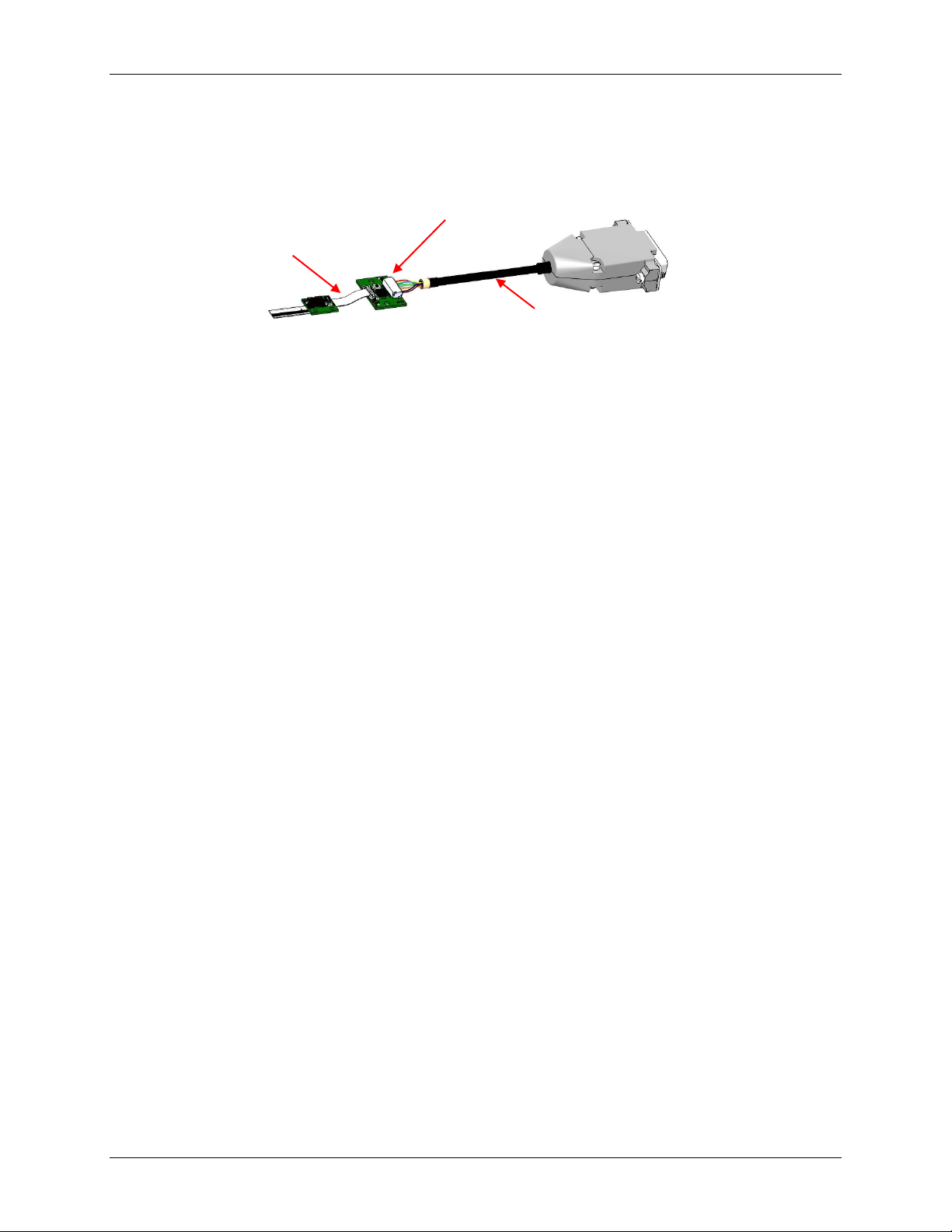
Connector and Calibration Board
Connected to sensor using the
200mm FFC from the development kit To customer's electronics
Connected to customer's electronics using the
3m controller cable from development kit
Sensor
MicroE Optira Installation Manual Celera Motion
IM-1001 | REV181211 Page 15 ©2018 Celera Motion
7.0 Appendix
7.1 Specifications
System
Operating and Electrical Specifications
Scales
Optira Series Encoders are compatible with Optira Tape
Scales, Linear Scales, and Rotary Glass Scales
Agency Standards Compliance in accordance with
Electromagnetic Compatibility Directive 2004/108/EC:
Scale Pitch 20 µm
EN55011, Class B:
EN 61000-4-3:
EN 60068-2-6:
EN 60068-2-27:
Radiated Emissions
Radiated Immunity
Vibration
Mechanical Shock
System
Resolution
5µm, 2.5 µm, 1 µm, 0.5 µm, 0.2 µm,
0.1 µm, 50 nm, 20 nm, 10 nm, 5 nm.
Analog 1 Vpp.
2,000 CPR – 75M CPR (rotary)
(specify resolution at time of ordering)
Power Supply Current
AquadB, 3.3 and 5 V
DC
±5%:
Analog, 3.3 and 5 VDC ±5%:
Ready Time:
<130 mA with 120Ω across A, B, I
<75 mA with no load
<100 mA with 120Ω across Sin/Cos, IW
<75 mA with no load
<0.5s once power >4.5 V
Accuracy
Tape
SDE:
Linearity:
Slope:
<100 nm RMS
<± 5 µm (max/meter)
<±150 µm/m
Temperature
Operating:
Storage:
0°C to 70°C
-20°C to 85°C Temperature
Linear Glass
SDE:
Total Accuracy:
<100 nm RMS
<±1 µm/m1
Humidity
Operating:
Storage:
Up to 85% RH, non-condensing
Up to 85% RH, non-condensing
Rotary Glass Total Accuracy: ±2 arc-seconds2
Vibration 10 g, 55 Hz to 2 KHz
Sensor Size and Weight
Mechanical
Shock
500 m/s2, 6 ms, ½ sine
Length
Width
Height
Outputs
Digital A-quad-B. A, B, Index outputs are differential
Alarm is single-ended open collector
Analog outputs are differential sine and cosine
Dimensions (mm): 13.0 11.4 3.7
Weight: <1.5 g sensor head
Sensor Cable
ZIF Flat Flexible Cable (FFC)
10 pins; length up to 5 m.
Signal Levels
A/B/I (differential); RS-422 compatible
A/B/I (single-ended): Voh min: Vcc - 0.4 VDC, Vol max: 0.4 VDC,
Alarm: Voh min: Vcc, Vol max: 0.4 VDC
Analog: 1 Vpp, 2.5 V offset @ 5 VDC; 1.65 V offset @ 3.3 VDC
Reliability Information
MTBF >200,000 hours under normal operating conditions
(calculated using MIL-STD-217)
Notes:
1. 130 mm or less
2. 125 mm diameter, excludes eccentricity
Maximum Velocity – Quadrature Output
Maximum Velocity (before Overspeed Buffer Protection3) vs. Interpolation Depth
Controller Recommended
AqB Maximum State
Rate (MegaStates/Sec)
Actual Encoder AqB
Maximum State Rate
(MegaStates/Sec)
5000
2500
1000
500
200
100
50
20
10
5
Resolution (nm)
4 8 20 40 100 200 400 1000 2000 4000
Interpolation Depth
20
14.50
4000
4000
4000
4000
2900
1450
300
290
145
72
Maximum
Velocity (mm/s)
10
7.25
4000
4000
4000
3625
1450
725
300
145
72
36
5
3.63
4000
4000
3625
1812
725
362
181
72
36
18
2
1.45
4000
3625
1450
725
290
145
72
29
14
7
1
0.73
3625
1812
725
362
145
72
36
14
7
3
Notes3:
1. Optira implements Overspeed Buffer Protection (OBP). No AqB counts are lost for velocities below 4830 mm/s even if the
maximum specified rate is exceeded. If the velocity exceeds the specified state rate, the AqB counts are buffered (buffer
length = 21 m at 4000x interpolation depth) and transmitted at the specified state rate.
2. The ALARM bit sets TRUE at 4 m/s, however, Optira will continue to produce valid AqB outputs up to
6 m/s although accuracy specifications are no longer guaranteed.
Maximum Velocity (Analog)
Sine/Cosine Vector Magnitude: > 0.5 Vpp at 4 m/s
Contact Celera Motion to discuss higher speed applications.
MicroE Optira Installation Manual Celera Motion
IM-1001 | REV181211 Page 16 ©2018 Celera Motion
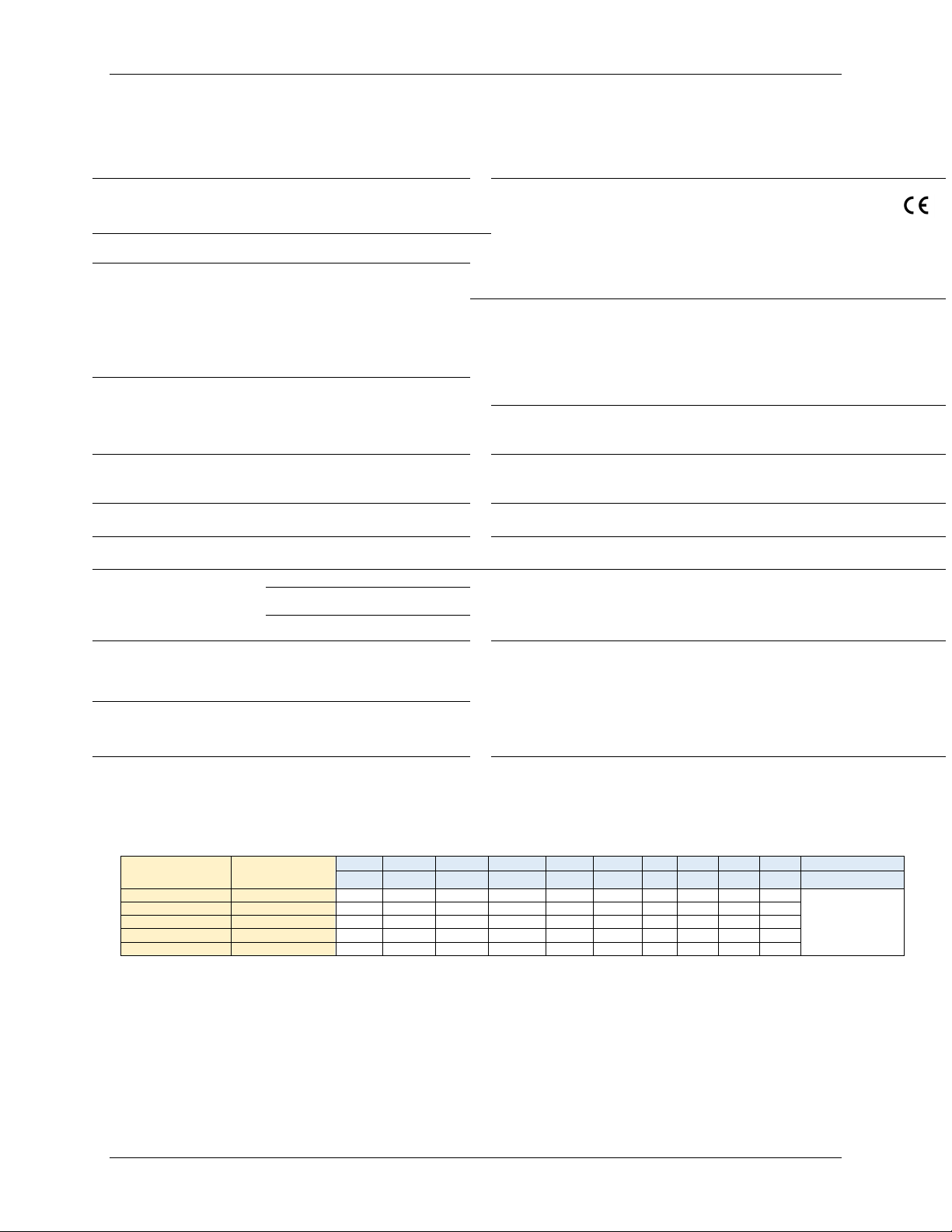
7.2 Power-Up Timing
The Optira encoder will be ready 420 ms after the 3.3 V or 5 V supply rises, during which the LED
will flash red and the Alarm signal will transition true. The encoder will be ready once the Alarm
transitions false per the following chart (5 V model is shown; chart also applicable for 3.3 V
model):
7.3 Sensor Connectors Pinouts
The following are the pinouts for the two connectors on the Optira sensor.
JP1 – Low Profile Board-to-Board Header Connector
Manufacturer Part Number: Molex®501594-1211
Pin
Number
Signal
A-quad-B
Analog
1
A+
SIN+
2
A-
SIN-
3
B+
COS+
4
B-
COS-
5
Index+
Index+
6
Index-
Index-
7
Alarm
Alarm
8
CAL
CAL
9
PWR
PWR
10
GND
GND
11
NC
NC
12
NC
NC
NC – No Connect
JP1 – Board-to-Board Header
Mating Connector1
Optira Sensor Top View
Note
1
: The 12-pin header mating connector has a limited
durability of 20 mating cycles maximum.
Optira Power Up Timing (low true Alarm)
Optira ready (420ms typ)
Internal Optira Reset
LED = red
Alarm = true
MicroE Optira Installation Manual Celera Motion
IM-1001 | REV181211 Page 17 ©2018 Celera Motion
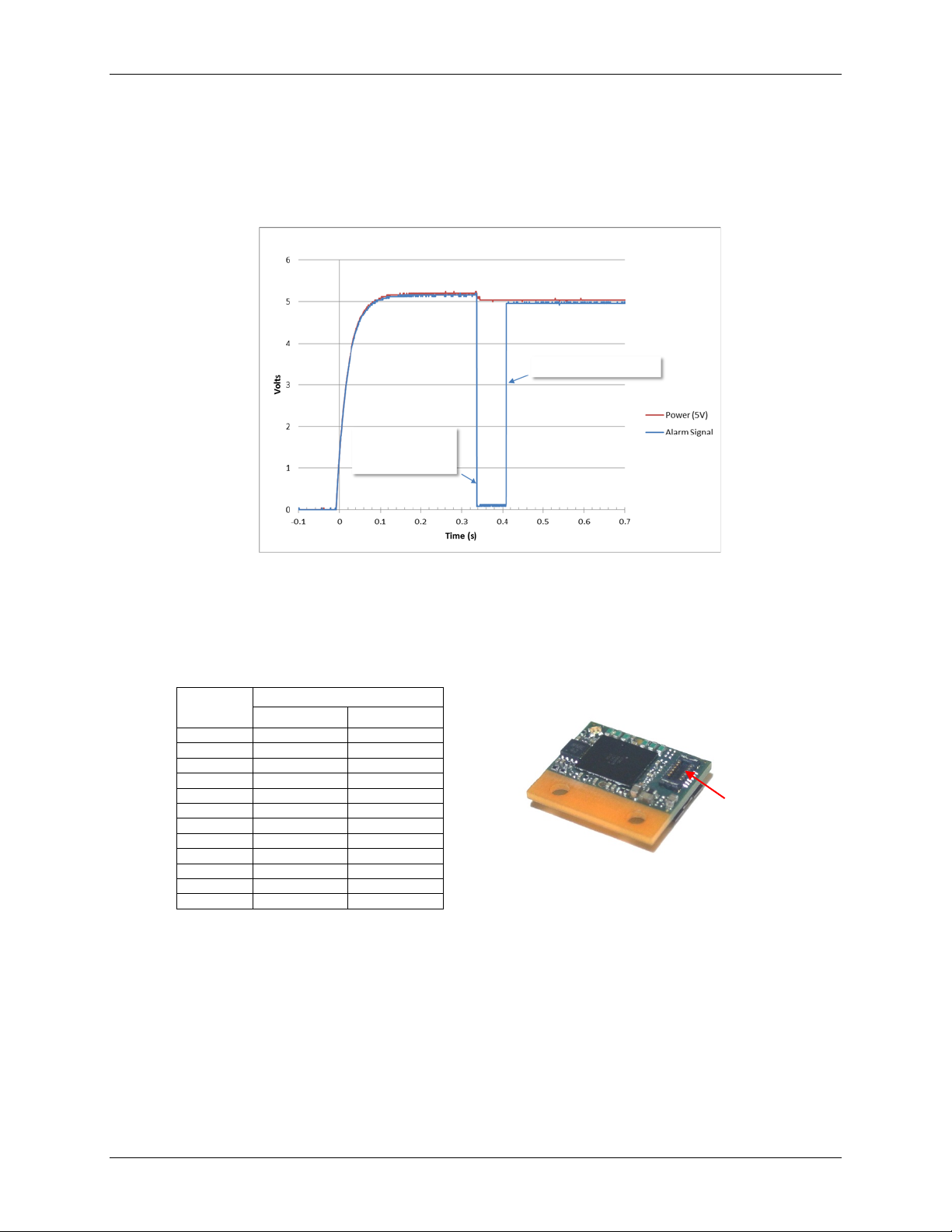
J1 - ZIF Connector
Manufacturer Part Number: Hirose®FH33J-10S-0.5SH(10)
Pin
Number
Signal
A-quad-B Analog
1
A+
SIN+
2
A-
SIN-
3
B+
COS+
4
B-
COS-
5
Index+
Index+
6
Index-
Index-
7
Alarm
Alarm
8
CAL
CAL
9
PWR
PWR
10
GND
GND
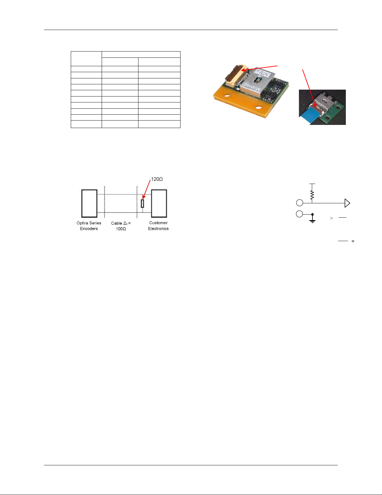
7.4 Recommended Signal Termination
Note: Below values are applicable for 5 V models only.
Digital/Analog Outputs Alarm Circuit Example
Alarm output is an open collector
circuit that is factory programmable:
either active high or active low;
specify when ordering. Alarm requires
an external pull-up resistor. See
customer-supplied circuit example on
right.
Note: Maximum cable length is 5 m. Contact MicroE Applications Engineering if longer lengths are
required.
J1 ZIF Connector
Optira Sensor Bottom View
R > Vcc
8mA
Vcc ≤ 5.5V
= 688Ω
R > 5.5V
8mA
R
Vcc
P7
P10
Alarm
Table of contents
Other Novanta Media Converter manuals

Popular Media Converter manuals by other brands


KanexPro
KanexPro EXT-SDI3G user manual

Avenview
Avenview C-COMPVGA-HDMI user guide

Denon
Denon DA-300USB Getting started

Hall Research Technologies
Hall Research Technologies SP-HD-8A user manual

TR-Electronic
TR-Electronic CEV115M 8192/4096 V000 PROFIBUS 85ZB14N manual

Addonics Technologies
Addonics Technologies ADIDESA installation guide