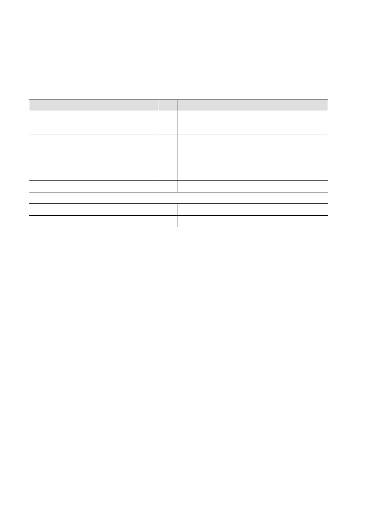
manuals.online logo
Brands
  1. Home
  2. •
  3. Brands
  4. •
  5. Lanner electronics
  6. •
  7. Motherboard
  8. •
  9. Lanner electronics MB-X62 Series User manual

Lanner electronics MB-X62 Series User manual

Other Lanner electronics Motherboard manuals

Lanner electronics MB-X63 Series User manual

Lanner electronics

Lanner electronics MB-X63 Series User manual

Lanner electronics IMB-X60 Series User manual

Lanner electronics

Lanner electronics IMB-X60 Series User manual

Lanner electronics AP-687VF User manual

Lanner electronics

Lanner electronics AP-687VF User manual

Popular Motherboard manuals by other brands

Gigabyte MNJ190I-FH user manual

Gigabyte

Gigabyte MNJ190I-FH user manual

Biostar HI-FI-Z87X-3D Setup manual

Biostar

Biostar HI-FI-Z87X-3D Setup manual

Atmel SAM9753PIA-DK user guide

Atmel

Atmel SAM9753PIA-DK user guide

Coapt GEN2 Handbook

Coapt

Coapt GEN2 Handbook

Supero SUPER P4DL6 user manual

Supero

Supero SUPER P4DL6 user manual

Cypress CY3210-PSoCEVAL1 quick start guide

Cypress

Cypress CY3210-PSoCEVAL1 quick start guide

ASROCK B660M-HDV manual

ASROCK

ASROCK B660M-HDV manual

Fujitsu D2831 Short description

Fujitsu

Fujitsu D2831 Short description

Industrial Computers ADE-6050 user manual

Industrial Computers

Industrial Computers ADE-6050 user manual

Asus TUF Z270 MARK 2 manual

Asus

Asus TUF Z270 MARK 2 manual

DFI NB71-BC user manual

DFI

DFI NB71-BC user manual

ASROCK H61 Pro BTC user manual

ASROCK

ASROCK H61 Pro BTC user manual

Norco POS-7893 user manual

Norco

Norco POS-7893 user manual

Intel DG965MS specification

Intel

Intel DG965MS specification

Asus B85M-VIEW PAKER user manual

Asus

Asus B85M-VIEW PAKER user manual

Asus P5G41T-M LX V2 user manual

Asus

Asus P5G41T-M LX V2 user manual

Gigabyte GA-K8VT800-RH user manual

Gigabyte

Gigabyte GA-K8VT800-RH user manual

Gigabyte Z790M AORUS ELITE user manual

Gigabyte

Gigabyte Z790M AORUS ELITE user manual

manuals.online logo
manuals.online logoBrands
  • About & Mission
  • Contact us
  • Privacy Policy
  • Terms and Conditions

Copyright 2025 Manuals.Online. All Rights Reserved.

Notice:
This MB-X62A/MB-X62B did not include DVI function, please ignore any description and
drawing concern DVI connection.
MB-X62 Series
Dual Pentium III ATX Mainboard
with VGA/DVI,
Three 100Base-TX Ethernet &
Dual-Channel Ultra 160 SCSI
for Socket 370 Processors
COPYRIGHT
©
This document is copyrighted by the original manufacture. The original manufacturer
reserves the right to make modifications to the product(s) described in this manual at any
time without notice. This manual may not, in whole or in part, be photocopied,
reproduced, transcribed, translated, or transmitted in whatever form without the written
consent of the manufacturer, except for copies retained by the purchaser for backup
purposes. All rights are reserved.
TRADEMARKS
Pentiumâis a registered trademark of Intel Corporation.
The following are trademarks or registered trademarks of their respective companies:
IBM, Intel, AMD, Cyrix, Award, AMI, S3, Microsoft, Windows, Windows NT, Novell, SCO,
PC/104, PICMG, ALI, UMC, SMC, Winbond. Products mentioned in this manual are for
identification purposes only. All names of products or services appearing in this manual
are the trademarks or registered trademarks of their respective organizations and
companies.
ãCopyright 2000
Ver. No.1.1
LEI-UM-MB-X62Series
Date: 2001/3/9
TABLE OF CONTENTS
CHAPTER1INTRODUCTION 1
1.1 SPECIFICATIONS 2
1.2 PACKING CHECK LIST 3
CHAPTER2JUMPER SETTING AND CONNECTORS 4
2.1 BOARD OUTLINE OF MB-X62 4
2.2 INSTALLING AND UPGRADING THE CPU 5
2.3 JUMPER SETTING OVERVIEW 7
2.4 JUMPER LOCATIONS FOR MB-X62 8
2.5 JUMPER SETTINGS SUMMARY FOR MB-X62 9
2.6 JUMPER SETTINGS FOR MB-X62 10
2.7 I/O CONNECTOR LOCATIONS FOR MB-X62 16
2.8 I/O CONNECTOR SUMMARY FOR MB-X62 17
2.9 SETTING STATUS INDICATORS AND CONTROL 18
CONNECTORS
2.10 I/O CONNECTORS DESCRIPTION 19
CHAPTER3AWARD BIOS SETUP 31
3.1 RUNNING AWARD BIOS 31
3.2 CMOS SETUP UTILITY 32
3.3 STANDARD CMOS SETUP 34
3.4 BIOS FEATURES SETUP 36
3.5 CHIPSET FEATURES SETUP 39
3.6 INTEGRATED PERIPHERALS 40
3.7 POWER MANAGEMENT SETUP 46
3.8 PNP/PCI CONFIGURATION 51
3.9 PC HEALTH STATUS 53
3.10 FREQUENCY / VOLTAGE CONTROL 54
3.11 LOAD FAIL-SAFE DEFAULTS 55
3.12 LOAD OPTIMIZED DEFAULTS 55
3.13 SET SUPERVISOR / USER PASSWORD 56
3.14 SAVE & EXIT SETUP 56
3.15 EXIT WITHOUT SAVING 56
TABLE OF CONTENTS
CHAPTER4DRIVERS SUPPORT 57
4.1 DRIVER DISKETTE LIST 57
APPENDIX A HOW TO USE WATCH-DOG TIMER 58
APPENDIX B TECHNICAL REFERENCE 59
GLOSSARY 61
TERMS AND CONDITIONS
RMA SERVICE REQUEST FORM
~ 1~
CHAPTER 1.
INTRODUCTION
The MB-X62 Series is a Duel Pentium III ATX Mainboard specifically designed for
Socket 370 with VGA/DVI, three 10/100Base-TX Ethernet ports as well as dual-channel
ultra 160 SCSI interface. With VIA 694X/686A chipsets, MB-X62 Series supports Ultra
DMA-33/66 for faster hard drive transmission speeds and contains health monitoring
hardware. The health monitoring IC keeps an eye on the CPU and releases an audio
alarm when detecting abnormal operating voltage & temperature or malfunction of the
cooling fans. For boosting operation, this motivated card also supports sockets for a
Flash Disk and four DIMMs.
Other on-board features include two serial ports (RS-232 and RS-232/422/485), one
multi-mode parallel (ECP/EPP/SPP) port, a floppy drive controller, a keyboard interface
and a PS/2 mouse interface. The built-in high speed PCI IDE controller supports both
PIO and bus master modes. Supporting up to two floppy disks, this board also can
connect up to four IDE devices, including large hard disks, CD-ROM drives, tape backup
drives and other IDE devices. Its 6-layer printed circuit board combined with
noise-tolerant and low power consumption CMOS technology allow the MB-X62 Series
to withstand many harsh industrial environments.
MB-X62 Series is a high power & full engine mainboard with an AGP display of
resolution up to 1600x1200 at 256 colors. Carefully designed to be a feature-rich
mainboard at a reasonable price, this board elegantly meets industry needs and saves
time and money by waiving the hassle of going through the extra effort and cost of
additional I/O cards. Being standards-compliant, it is proved to be a quality product with
high performance and stability in a long run.
INTRODUCTION
~ 2~
1.1 SPECIFICATIONS
oProcessor :Dual Intel Pentium III/CeleronTM Processor in
Socket 370, support FSB 66/100/133 MHz CPU
oChipset :VIA 694X/686A chipset
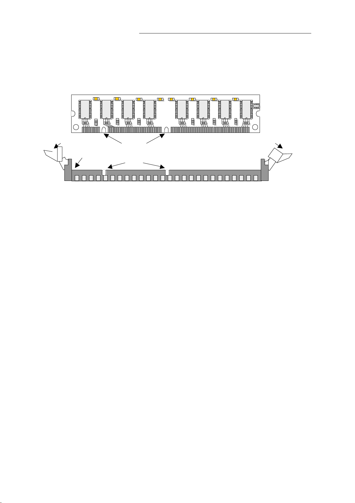
oSystem Memory/RAM :Four 168-pin DIMM sockets( recommend memory
support 4 DIMMs up to 2 GB SDRAM at 100 MHz or 3
DIMMs up to1.5GB SDRAM at 133 MHz max.)
oBIOS :Award Licensed BIOS (2MB Flash ROM)
oFlash Memory Disk :Reserved socket for DiskOnChip from M-System,
support up to 144 MB Flash memory disk
oAGP VGA Controller :ATI Rage XL, with 8MB Video memory
oSCSI Controller :LSI SYMBIOS SYM53C1010 Dual Channel Ultra160
SCSI chip
oEthernet Controller :Three Realtek RTL8139C chip, support
10/100BASE-TX on-board RJ-45 connector, with
Wake-On-LAN function
oIDE Drive Interface :Two PCI IDE ports, support up to four IDE devices and
Ultra DMA33/66
oFloppy Drive Interface :One FDD port, support up to two floppy devices
oSerial Port :Two COM ports, support one RS-232 and one
RS-232/422/485
oParallel Port :One multi-mode parallel port (SPP/EPP/ECP)
oBus Interface :One PCI bus interface
oRTC Battery :Internal RTC with Li battery
oKeyboard/Mouse Connector: 6-pin mini-Din PS/2 keyboard/mouse connector with
5-pin keyboard header
oWatchdog Timer :16-level time-out intervals
oUniversal Serial Bus :Support two USB connectors
oIR Interface :Support one IrDA header
oHealth Monitoring :On-board Genesys 518SM Monitoring IC
oPower Consumption :5.45A@+5V(PentiumⅢ933MHz CPU*2 with 512MB
SDRAM module*4)
oOperating Temperature :0°C~60°C (32°F~140°F)
oHumidity :10%~95%RH, non-condensing
oDimensions :ATX form factor 305 X 244 mm ± 5%(12.0” X 9.6”)
oNet Weight :500g (1.1 pounds)
INTRODUCTION
~ 3~
1.2 PACKING CHECK LIST
Inspect the product package for the following items before installation. If there is anything
missing, please contact our authorized reseller.
Item Qty Remark
MB-X62 1 pc MB-X62 Dual Pentium III Mainboard
FDD cable 1 set 34-pin to 34-pin standard header flat ribbon cable
COM2 port cable 1 set 10-pin female flat connector header to 9-pin male
D-Sub connector with bracket
IDE Cable 1 pc IDE cable 45cm
Drivers Utility 1 pc CD-ROM
User‘s manual 1 pc MB-X62 user’s manual
*Optional Item
Ultra 160 SCSI Cable 1 pc 080050078001
FAN with Heat-sink(For 1U application) 1 pc 0820103M00001
~ 4~
JUMPER SETTING AND CONNECTORS
The figure below shows the jumpers and connectors location on the MB-X62 Series. The
PCB version may differ for slight changes without notice.
2.1 Board Outline of MB-X62 Series
CHAPTER 2.
JUMPER SETTING AND CONNECTORS
~ 5~
2.2INSTALLING AND UPGRADING THE CPU
To upgrade to a higher power CPU, simply remove the old CPU and install a new one.
Make sure to set the jumpers for the new CPU type and speed.
WARNING!
Disconnect the power cord from your system when you intend to
work on it or when you plan to open the chassis of your industrial
computer. Do not make connections when the power is turned on
because the sens
itive electronic components could be damaged
by the sudden rush of power. Please only allow experienced
electronic technicians to do this job.
STATIC ELECTRICITY PRECAUTION!
Caution! Computer components are very sensitive to damage
from static electric
discharge. Always ground yourself to remove
static charge build-
up before touching the boards in the computer.
Use a grounding wrist strap at all times. Place all electronic
components on anti-static pad for static-
dissipation or in
static-shielded bag when they are not in the chassis.
CAUTION!
Danger of explosion if battery is incorrectly replaced. Replace
only with the same or equivalent type recommended by the
manufacturer. Dispose of used batteries according to the battery
manufacturer’s instruct
ions or accepted environmental regulatory
standards.
JUMPER SETTING AND CONNECTORS
~ 6~
¥
INSTALLING THE DIMM MODULE:
A DIMM module simply snaps into a socket on the system board. Pin1 of the DIMM
module must correspond with Pin1 of the socket.
1. Pull the “tabs” which are at the ends of the socket to the side.
2. Position the DIMM above the socket with the “notches” in the module aligned with the
“keys” on the socket.
3. Seat the module vertically into the socket. Make sure it is completely seated. The tabs
will hold the DIMM in place.
Pin1 Notch
Key
TabTab