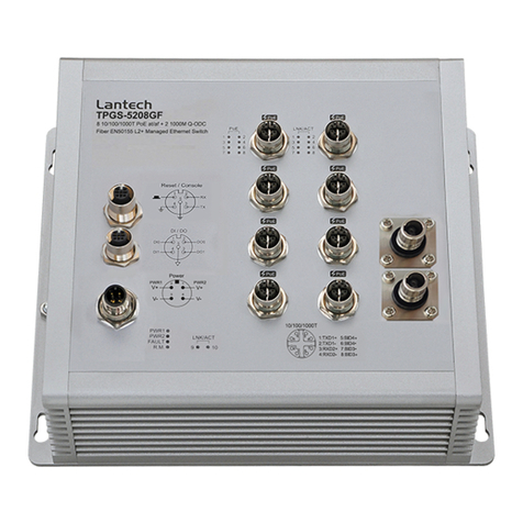
Lantech IGS-3408GSFP User manual

ImportantNotice
LantechCommunicationsGlobal,Inc.reservestherighttomodifythe
equipment, itsspecificationorthismanualwithoutpriornotice,inthe interest
ofimproving performance,reliability,orservicing.Atthetimeofpublication
alldataiscorrectforthe operationofthe equipmentatthevoltageand/or
temperaturereferred to.Performance dataindicatestypicalvaluesrelated to
theparticularproduct.
Nopartofthisdocumentationorinformationsuppliedmaybedivulgedtoany
thirdpartywithouttheexpresswritten consentof LantechCommunications
GlobalInc.Productsoffered maycontainsoftwarewhichisproprietaryto
LantechCommunicationsGlobalInc.The offerorsupplyoftheseproducts
and servicesdoesnotinclude orinferanytransferofownership.
Interference Issues
ThisEquipmenthasbeentested and found tocomplywiththe limitsfora
Class Adigitaldevice,pursuanttoPart15 ofthe FCC rules.Theselimitsare
designed toprovidereasonableprotectionagainstharmfulinterferenceina
commercialorindustrialinstallation.Thisequipmentgenerates,uses,and
canradiateradiofrequency energy.It maycauseharmfulinterferenceto
radiocommunicationsifthe equipmentisnotinstalled and usedin
accordancewiththeinstructions.
FCC Warning
ThisEquipmenthasbeentested and found tocomplywiththe limitsfora
Class-A digitaldevice,pursuanttoPart15 oftheFCC rules.Theselimits
aredesigned toprovidereasonableprotection againstharmfulinterference
inaresidentialinstallation.Thisequipmentgenerates,uses,and can
radiateradiofrequencyenergy.It maycauseharmfulinterferencetoradio
communicationsifthe equipmentisnotinstalledand used inaccordance
withtheinstructions.However,thereisnoguarantee thatinterferencewill
notoccurinaparticularinstallation.If thisequipmentdoescauseharmful
interferencetoradioortelevisionreception,whichcan be determined by
turning theequipmentoff and on,theuserisencouraged totrytocorrect
theinterferencebyone ormoreofthefollowingmeasures:
Reorientorrelocatethe receiving antenna.
Increasethe separation betweentheequipmentand receiver.
Connecttheequipmentintoan outleton acircuitdifferentfromthatto
whichthe receiverisconnected.
Consultthedealeroran experiencedradio/TVtechnician forhelp.
CEMarkWarning
ThisisaClass-A product. Inadomesticenvironmentthisproductmay
causeradiointerferenceinwhichcasethe usermaybe required totake
adequatemeasures.

Content
Chapter1 Introduction ...........................................1
HardwareFeatures................................................. 1
SoftwareFeatures.................................................. 3
Chapter2 HardwareDescription............................8
2.1 PhysicalDimension....................................... 8
2.2 IPProtection................................................10
2.3 LEDIndicators.............................................13
Chapter3 HardwareInstallation ..........................14
3.1Hardwareinstallation........................................14
3.2 DIN-Rail Mounting........................................15
3.3 WallMount PlateMounting..........................17
3.4 Wiring the PowerInputs...............................18
3.5 Wiring the FaultAlarmContact ....................19
3.6 Cabling........................................................20
3.7 USBDongle(IGS/IPGS-5xxxseries)............23
Chapter4 NetworkApplication............................ 24
ITUG.8032 Scheme..............................................24
RingCoupling ..........................................................24
MultipleRings..........................................................25
DualHoming ...........................................................25
Chain......................................................................25
Chapter5 ConsoleManagement..........................28
5.1 Connectingtothe ConsolePort....................28
5.2 LoginintheConsoleInterface......................29
Chapter6 Web-BasedManagement.................... 30
6.1 AboutWeb-based Management...................30
6.2 PreparingforWeb Management..................30
6.3 SystemLogin...............................................31
6.4 System.........................................................32
6.4.1SystemIdentification Configuration...................... 32
6.4.2SwitchInformation................................................33
6.4.3IPconfiguration.....................................................33
6.4.4DHCPserver.........................................................35
6.4.5 SystemTime................................................... 36
6.4.6SNMPConfiguration.......................................... 40
6.4.7Fault RelayConfiguration..................................41
6.4.8 DigitalInput/Output.......................................43
6.5 Event&Log................................................45
6.5.1ViewLogs............................................................. 45
6.5.2Events................................................................... 46
6.5.3DDMevent............................................................47
6.5.4Actions..................................................................48
6.5.5EventActionMap................................................. 51
6.6Ports................................................................53
6.6.1DeviceSettings.....................................................53
6.6.2Status.................................................................54
6.6.3Statistics............................................................... 54
6.6.4Mirroring................................................................55
6.6.5RateLimiting.........................................................56
6.6.6LoopProtection.....................................................57
6.7PoweroverEthernet (IPGSseries)..................58
6.7.1Configuration ........................................................ 58

6.7.2Status....................................................................59
6.7.3Detection............................................................... 61
6.7.4Scheduling............................................................62
6.8Topology..........................................................63
6.9QoS.................................................................66
6.9.1QoSPolicy............................................................66
6.10 Security.........................................................68
6.10.1MACAddress Tables.......................................... 68
6.10.2AccessControlList............................................. 69
6.10.3IEEE802.1XRadiusServer............................... 70
6.10.4IPSecurity.......................................................... 71
6.11 VLAN.............................................................72
6.11.1802.1QVLANConfig.......................................... 72
6.11.2Status..................................................................74
6.12 MVR..............................................................75
6.12 LLDP.............................................................76
6.12.1LLDPConfiguration............................................ 76
6.12.2LLDPNeighbor................................................... 77
6.12.3LLDPStatistics................................................... 79
6.13 CDP...............................................................82
6.13.1CDPConfigurationDeviceSettings................... 82
6.13.2CDPPortConfiguration......................................83
6.13.3. CDPStatus........................................................ 83
6.14 IGMPSnooping.............................................85
6.14.1IGMPSnooping Configuration............................86
6.14.2IGMPSnooping Status.......................................87
6.15 MSTP............................................................89
6.15.1.MSTPGlobalConfiguration.......................89
6.15.2HowtoenableMSTP.......................................... 90
6.15.3CISTSettings...................................................... 92
6.15.3.1Bridgeconfiguration.......................... 92
6.15.3.2Port....................................................92
6.15.4. MSTPMSTISettings.........................................93
6.15.5. MSTPBridgesStatus........................................ 94
6.15.6. Bridgestatusof all ports....................................95
6.16 Aggregation................................................96
6.16.1. Aggregation Configuration.................................96
6.16.2LACPPortStatus...............................................97
6.17 PTPIEEE 1588 v2(IGS/IPGS-5xxxseries)...98
6.18 G.8032 ERPS..............................................100
6.18.1. G.8032EthernetRingProtectionConfiguration100
6.18.2HowtosetERPSG.8032.................................101
6.19 Dual Homing.............................................104
6.20 Maintenance................................................106
6.20.1SaveConfiguration...........................................106
6.20.2 Configbackup/restore................................106
6.20.3Restart device...................................................107
6.20.4FirmwareUpgrade............................................108
6.20.5Diagnostics.......................................................108
Appendix Command Linemode......................111

1
Chapter1Introduction
LantechFullgigabit series(include IGS-3408/5408GSFPand IPGS-3408/5408GSFP)
arehigh performanceL2+industrialGigabituplinkswitcheswith8x10/100/1000T+4
Giga SFPw/8PoEat/afinjectors(IPGSseries)whichprovidesL2 wirespeed and
advancedsecurityfunctionforconnecting PDnetwork.TheydeliversITUG.8032 ring
recoverylessthan50ms,comprehensiveQoS, , IGMPv1/v2/v3&routing,QinQ(double
tagVLAN), MVR(multicast VLANregistration),LACPlinkaggregation and advanced
securityincluding ACL,TACAS+*,SSH/SSL,DHCPOption82*whichareimportant
featuresrequiredinlargenetwork.It alsosupportsCiscoDiscoveryProtocol(CDP) and
LLDPforCiscoworks todetecttheswitchinfotobeshownonL2 maptopology.The
userfriendlyUI, innovativeautotopologydrawing and topologydemomakesLantech
Fullgigabitseriesmucheasiertogethands-on.
HardwareFeatures
Standard
IEEE 802.310Base-TEthernet
IEEE 802.3u 100Base-TX
IEEE802.3zGigabitfiber
IEEE802.3xFlowControl and BackPressure
IEEE802.3ad PorttrunkwithLACP
IEEE802.1d Spanning Tree
IEEE802.1wRapidSpanning Tree
IEEE802.1sMultipleSpanning Tree
IEEE 802.3adLinkAggregation ControlProtocol(LACP)
IEEE 802.1AB LinkLayerDiscoveryProtocol(LLDP)
IEEE 802.1XUserAuthentication(Radius)
IEEE802.1p ClassofService
IEEE802.1QVLANTag
IEEE802.3at/afPoweroverEthernet
Switch
Architecture
Back-plane (Switching Fabric):24Gbps
Packetthroughput ability(Full-Duplex): 60Mpps@64bytes
2
TransferRate
14,880ppsforEthernetport
148,800ppsforFastEthernetport
1,488,000ppsforGigabitEthernetport
MACAddress 16KMACaddresstable
Connector
10/100/1000T: 8xRJ-45 typeconnector
Mini-GBIC:4x1000 SFPSockets
Power&P-Failconnector:1x6-poleterminalblock
DigitalInput/Output: 1x6-poleterminalblock
RS-232 connector:1xRJ-45 typeconnector
USB forautomaticbackup and configuration(IGS/IPGS-
5xxx series)
NetworkCable 10/100/1000T: 2-pairUTP/STPCat. 5/5E/ 6cable
EIA/TIA-568100-ohm(100m)
Protocol CSMA/CD
LED
Perunit: Power1(Green),Power2(Green),P-Fail(Red)
Ethernetport: Link/Activity(Green),Speed(Green);Giga-T
:
Link/Activity(Green)
PoEFWD: Green(IPGS)
DI/DO
1DigitalInput(DI):
Level 0: -30~2V/Level1:10~30V
Max.inputcurrent:8mA
1DigitalOutput(DO):opencollectorto40VDC,200mA
PowerSupply
48 VDC for802.3af(IPGSseries)
54VDC for802.3at(IPGSseries)
24~48VDC (IGSseries)
Power
Consumption Max10Wforsystem
PoEPower
Budget Max.240Wunder48VDCpowerinput (IPGSseries)
Operating
Humidity 5% to95% (Non-condensing)

3
Operating
Temperature -40oC~75oC
Storage
Temperature -40oC~85oC
Case Dimension
Metalcase.IP-30,
74(W)x105 (D)x152 (H)mm
Metalcase.IP-30, forIPGS-xxxx-E wide Temp.series
96.3(W)x105 (D)x152 (H)mm
Installation DINrailand wallmountear**
EMI
FCC ClassA, CEEN61000-4-2,CEEN61000-4-3, CEEN-
61000-4-4,CEEN61000-4-5,
CEEN61000-4-6,CEEN61000-4-8,CEEN61000-4-
11,CE
EN61000-4-12,CEEN61000-6-2,CEEN61000-6-4
StabilityTesting IEC60068-2-32 (Freefall),IEC60068-2-27 (Shock),
IEC60068-2-6(Vibration)
SoftwareFeatures
Management SNMPv1v2c,v3/Web/Telnet/CLI
SNMPMIB
RFC1215 TrapsMIB,
RFC1213 MIBII,
RFC1157 SNMPMIB,
RFC1493 Bridge MIB,
RFC2674 VLANMIB,
RFC1643 EtherLike,
RFC1757 RMON,
RSTPMIB,
PrivateMIB,
LLDPMIB
4
ITUG.8032
SupportITUG.8032 v2forRing protection inless than
10ms forself-healrecovery<256 switches;
Supportvariousring/chaintopologies
Ring coversdata&multicast*packets
UserfriendlyUI
Autotopologydrawing
Topologydemo
Autoconfiguration forG.8032*
PortTrunkwith
LACP
LACPPortTrunk:4Trunkgroups/Maximum4trunk
members
Loadbalancing throughLACPtodistributeload*
LLDP SupportsLLDPtoallowswitchtoadviseitsidentification
and capabilityonthe LAN
CDP
CiscoDiscoveryProtocolfortopologymapping
PoE
Management
(IPGSseries)
PoEDetection tocheck ifPDishangup then restartthe
PD
PoEschedulingtoOn/Off uponroutinetimetable
PerportPoEstatusincludevoltage currentand watts
VLAN
PortBased VLAN
IEEE 802.1QTagVLAN(256 entries)/VLANID(Upto4K,
VLANIDcanbeassigned from1to4096.)
GVRP(256Groups)*,GMRP*,MVRP(MultiVLAN
Registration),QinQ*
Network
Security
Support10 IPaddressesthathavepermission toaccess
theswitchmanagementand topreventunauthorized
intruder.
802.1Xaccesscontrolforportbased and MACbased
authentication/MAC-IP-Portbinding

5
Managementaccess controlwithpriority*
256 PolicybasedAccess ControlList*
SSL/ SSHforManagement
TACACS+forAuthentication*
SMTP/TextSMS
SupportsSMTPServerand 6e-mail accountsfor
receiving eventalert;cansend SMStextalertviamobile
SpanningTree
SupportsIEEE802.1d Spanning Treeand IEEE802.1w
RapidSpanning Tree,IEEE802.1sMultiple Spanning Tree
QualityofService
The qualityofservicedeterminedbyport, Tag and IPv4
Typeofservice,IPv4DifferentService
Class ofService SupportsIEEE802.1p classofservice,perportprovides4
priorityqueues
IPSecurity
Supports10 IPaddressesthathavepermissiontoaccess
theswitchmanagementand topreventunauthorized
intruder.
Login Security SupportsIEEE802.1XAuthentication/RADIUS
PortMirror Support3mirroring types: RX,TXand Bothpacket
IGMP
SupportIGMPsnooping v1,v2,v3;SupportsIGMPstatic
route
256 multicastgroupsand IGMPquery
MulticastVLAN
Registration*
MVRenablesmulticastpacketsgothrough VLANforVOD
application
Bandwidth
Control
Supportingress packetfilterand egresspacketlimit.
The egress ratecontrolsupportsallofpackettype.
Ingressfilterpackettypecombination rulesare
6
Broadcast/Multicast/Flooded Uni-castpacket,
Broadcast/Multicastpacket, Broadcastpacketonlyand all
typesofpacket.
The packetfilterratecan besetan accuratevalue through
thepull-downmenu fortheingresspacketfilterand the
egress packetlimit.
RTC Built-inRealTimeClock tokeeptrack oftimealways
FlowControl SupportsFlowControlforFull-duplexand BackPressure
forHalf-duplex
System Log SupportsSystemlog recordand remotesystemlogserver
SMTP SupportsSMTPServerand 6e-
mail accountsforreceiving
eventalert
RelayAlarm Providesone relayoutputforportbreakdown,powerfail
AlarmRelaycurrentcarryability:1A@DC24V
SNMPTrap
1.TopologyChange
2.PowerTrap
3.MAC-Violation
DHCP ProvidesDHCPClient/ DHCPServer/Portand IPBinding
DNS ProvidesDNSclientfeatureand supportsPrimaryand
SecondaryDNSserver
SNTP SupportsSNTPtosynchronizesystemclock inInternet
FirmwareUpdate
SupportsTFTPfirmwareupdate,TFTPbackup and restore.

7
Configuration
Upload/Download Supportstextconfiguration fileforsystemquick installation
;
ifAlias Eachportallowsanalphabeticstring of128-byteassigned
asitsownunique nameviatheSNMPorCLIinterface
8
Chapter2HardwareDescription
information,and wiring installation.
2.1PhysicalDimension
Metalcase.IP-30,
74(W)x105 (D)x152 (H)mm

9
Metalcase.IP-30, forIPGS-xxxx-E wide Temp.series
96.3(W)x105 (D)x152 (H)mm
10
2.2IPProtection
The IPCode, Ingress Protection Rating,sometimesalsointerpreted as International
Protection Rating,classifiesand ratesthedegree ofprotectionprovided againstthe
intrusion(including bodypartssuchashandsand fingers),dust, accidentalcontact, and
waterin mechanicalcasings and withelectricalenclosures.It ispublishedbythe
InternationalElectrotechnicalCommission(IEC)
Solidparticleprotection
The firstdigitindicatesthelevelofprotection thattheenclosureprovidesagainstaccess
tohazardousparts(e.g., electricalconductors,moving parts)and the ingressofsolid
foreign objects.
Level
Objectsize
protectedagainst
Effective against
0
Noprotection againstcontactand ingressofobjects
1 >50 mm
Anylargesurfaceofthe body,suchasthe backofa
hand,butnoprotection againstdeliberatecontact
withabodypart
2
>12.5mm Fingersorsimilarobjects
3
>2.5mm Tools,thick wires,etc.
4
>1mm Mostwires,screws,etc.
5 Dustprotected
Ingressofdustisnotentirelyprevented,butitmust
notenterinsufficientquantitytointerferewiththe
satisfactoryoperationoftheequipment; complete
protection againstcontact
6 Dusttight Noingress ofdust; completeprotection against
contact

11
Liquid ingress protection
The second digitindicatesthe levelofprotection thatthe enclosureprovidesagainst
harmfulingressofwater.
Level
Protected
against Testing for Details
0
Not
protected
1
Dripping
water
Dripping water(vertically
falling drops)shall haveno
harmfuleffect.
Testduration:10minutes
Waterequivalentto1mm
rainfallperminute
2
Dripping
waterwhen
tiltedup to
15°
Verticallydripping water
shal
lhavenoharmfuleffect
whenthe enclosureistilted
atanangleup to15°from
itsnormalposition.
Testduration:10minutes
Waterequivalentto3mm
rainfallperminute
3
Spraying
water
Waterfalling asasprayat
anyangleup to60°from
the verticalshallhaveno
harmfuleffect.
Testduration:5minutes
Watervolume:0.7litresper
minute
Pressure:80 100 kPa
4
Splashing
ofwater
Watersplashing against
theenclosurefromany
directionshallhaveno
harmfuleffect.
Testduration:5minutes
Watervolume:10 litresper
minute
Pressure:80 100 kPa
5
Waterjets Waterprojectedbya
nozzle(6.3mm)against
enclosurefromany
directionshallhaveno
harmfuleffects.
Testduration:atleast
15minutes
Watervolume:12.5
litresper
minute
Pressure:30kPaa
tdistance
of3m
6
Powerful
Waterprojected inpowerful
Testduration:atleast
12
waterjets jets(12.5mm nozzle)
againstthe enclosurefrom
anydirection shallhaveno
harmfuleffects.
3minutes
Watervolume:100 litresper
minute
Pressure:100 kPaat
distanceof3m
7
Immersion
up to1m
Ingressofwaterinharmful
quantityshallnotbe
possiblewhenthe
enclosureisimmersedin
waterunderdefined
conditionsofpressureand
time(up to1mof
submersion).
Testduration:30minutes
Immersionatdepthofat
least1mmeasuredat
bottomofdevice,and atleast
15cm measuredattopof
device
8
Immersion
beyond 1m
The equipmentissuitable
forcontinuousimmersionin
waterunderconditions
whichshallbespecified by
the manufacturer.
Normally,thiswillmean
thattheequipmentis
hermeticallysealed.
However,withcertaintypes
ofequipment, itcan mean
thatwatercan enterbut
onlyinsuchamannerthat
itproducesnoharmful
effects.
Testduration:continuous
immersion in water
Depthspecified by
manufacturer
9
Powerful
high
temperature
waterjets
Protected againstclose-
range high pressure,high
temperaturespraydowns.

13
2.3LEDIndicators
ThediagnosticLEDsthatprovidereal-timeinformation ofsystemand optionalstatusare
located onthefrontpaneloftheindustrial switch.The following tableprovidesthe
descriptionoftheLEDstatusand theirmeaningsfortheswitch.
LEDColor Status Meaning
R.M Green On The switchunit isownerswitchofITU-Ring
Off The switchisnotownerswitch
PWR1 Green On Power1isactive
Off Power1isinactive
PWR2 Green On Power2isactive
Off Power2isinactive
FAULT Red On Powerorportfailure
Off Nofailure
P1~P8
Link/Ack
On Anetworkdeviceisdetected.
Blinking
The portistransmitting o
rreceiving packets
fromtheTXdevice.
Off Nodeviceattached
Speed1000M
On The portisoperating in 1000Tmode.
PoEFWD Off The portisnot operating inPoEmode.
On The portisoperating in PoEmode.
P9~P12 9,10,11,12
On Anetworkdeviceisdetected.
Blinking
The portistransmitting orreceiving packets
fromtheTXdevice.
Off Nodeviceattached.
14
Chapter3HardwareInstallation
3.1Hardwareinstallation
1.UnpacktheIndustrialswitch
2.Check iftheDIN-Railisscrewedonthe Industrialswitchornot. Ifthe DIN-Railisnot
screwedon the Industrial switch,pleasereferto DIN-Rail Mounting sectionforDIN-
Railinstallation.If userswanttowallmountthe Industrial switch,pleasereferto Wall
MountPlateMounting section forwall mountplateinstallation. NOTE:Wall mount
kitsareoptionalaccessories.
3.Tohang theIndustrialswitchontheDIN-Railtrack orwall.
4.PowerontheIndustrialswitch.Pleaserefertothe Wiring thePowerInputs section
forknowing theinformationabouthowtowirethepower.ThepowerLEDon the
Industrialswitchwilllightup.Pleaserefertothe LEDIndicators sectionforindication
ofLEDlights.
5.Preparethetwisted-pair,straightthrough Category5cableforEthernetconnection.
6.Insertone sideofRJ-45 cable(category5)intothe IndustrialswitchEthernetport
(RJ-45 port)and anothersideofRJ-
Ethernetport(RJ-45 port),ex:SwitchPCorServer.The UTPport(RJ-45)LEDon
theIndustrialswitchwilllightup when the cableisconnectedwiththe networkdevice.
Pleaserefertothe LEDIndicators section forLEDlightindication.
[NOTE]
MakesurethattheconnectednetworkdevicessupportMDI/MDI-X.If itdoesnot
support, usethe crossovercategory-5cable.
7.When allconnectionsaresetand LEDlightsallshowinnormal,the installation is
complete.

15
3.2DIN-Rail Mounting
The DIN-Railisscrewedon theindustrialswitchwhen outoffactory.IftheDIN-Railis
notscrewedonthe industrial switch,pleaseseethe following picturestoscrewtheDIN-
Railonthe switch.Followthestepsbelowtohang the industrialswitch.
16
1. First, insertthe top ofDIN-Railintothetrack.
2. Then,lightlypushthe DIN-Railintothetrack.
3. Check iftheDIN-Railistightened onthetrack ornot.
4. Toremovethe industrialswitchfromthe track,reverseabovesteps.

17
3.3WallMountPlateMounting
Followthestepsbelowtomounttheindustrial switchwithwallmountplate.
1.Removethe DIN-Rail fromtheindustrialswitch;loosethescrewstoremovethe DIN-
Rail.
2.Placethe wallmountplateontherearpaneloftheindustrialswitch.
3.Usethe screwstoscrewthewallmountplateontheindustrialswitch.
4.Usethe hookholesatthecornersofthe wall mountplatetohang theindustrial
switchonthe wall.
5.Toremovethe wallmountplate,reversetheabovesteps.
NOTE:Wall mountkitsareoptionalaccessories
18
3.4WiringthePowerInputs
Pleasefollowthestepsbelowtoinsertthe powerwire.
1.InsertACorDC powerwiresintothecontacts1and2forpower1,or5and 6for
power.
2.Tighten the wire-clampscrewsforpreventing thewiresfromloosing.
[NOTE]
The wiregauge forthe terminalblockshouldbein therange between12 ~24
AWG.

19
3.5WiringtheFaultAlarmContact
The faultalarmcontactsareinthemiddleoftheterminalblock connectorasthepicture
showsbelow.Inserting the wires,the switchwilldetectthefaultstatusofthe power
failure,orportlinkfailure(available formanagedmodel)and thenforms anopen circuit.
The following illustrationshowsanapplicationexampleforwiring thefaultalarmcontacts.
[NOTE]
The wiregauge forthe terminalblockshouldbein therange between12 ~24
AWG.
Insertthewiresintothe faultalarmcontacts
20
3.6Cabling
Usefourtwisted-pair,Category5eorabovecablingforRJ-45 portconnection.The
cablebetweentheswitchand thelinkpartner(switch,hub,workstation,etc.)must
be lessthan100 meters(328 ft.)long.
Fibersegmentusing single-mode connectortypemustuse9/125 µmsingle-mode
fibercable.Usercan connecttwodevicesin the distanceup to 30km.
Fibersegmentusing multi-mode connectortypemustuse50 or62.5/125 µmmulti-
mode fibercable.Usercan connecttwodevicesup to 2kmdistances.
GigabitSFP(mini-GBIC)port:
The smallform-factorpluggable (SFP) isacompactoptical transceiverused inoptical
communicationsforbothtelecommunicationand datacommunications.The SFPslots
supporting Gigabit speedup to1000Mbps.Theyareusedforconnecting tothenetwork
segmentwithsingleormulti-mode fiber.Youcan choosetheappropriateSFP
transceivertoplug intotheslots.Thenusepropermulti-mode orsingle-mode fiber
according tothetransceiver.Withfiberoptic,ittransmitsatspeedup to1000 Mbpsand
youcanpreventnoiseinterferencefromthesystem.
Toconnectthetransceiverand LCcable,pleasefollowthe stepsshownbelow:
First, insertthe transceiverintothe SFPmodule.Noticethatthe trianglemarkisthe
bottomofthe module.
Transceiver tothe SFPmodule

21
Transceiver Inserted
Second,insertthefibercableof LCconnectorintothetransceiver.
LC connector tothe transceiver
22
Toremovethe LCconnectorfromthetransceiver,pleasefollowthe stepsshownbelow:
First, pressthe uppersideoftheLCconnectortoreleasefromthetransceiverand pullit
out.
RemoveLCconnector
Second,pushdownthe metalloopand pullthetransceiveroutbytheplastichandle.
Pullout fromthe transceiver

23
3.7USBDongle(IGS/IPGS-5xxx series)
The USB slotistobackup and restorethesetting ofswitchautomaticallybyanyUSB
dongle.It doesn tneedanyconfigurationfromweb browserorotheruserinterface.
24
Chapter4NetworkApplication
ITUG.8032 Scheme
Lantech G.8032protocolisfollowingITU(InternationalTelecommunication Unit) G.8032
v2draft. The benefitsofG.8032 are:
1.<50msrecoverytimewhenfailover
2.G.8032 hasdefined theprotocolscheme,parameters,functions,testmeasurestobe
unified thattheuserscan evaluatethepossiblenetworkinfrastructurewithoutliterally
testing eachbrand inlargescale.
RingCoupling
1-1.SingleCoupling
1-2.RedundantCoupling
1-3.RedundantCoupling with MultipleRings

25
MultipleRings
1-4.DualRings
1-5.MultipleRings
DualHoming
Chain
1-6.SingleChain
26
1-7.MultipleChains
1-8.MultipleChainsShareCommon Ends
1-9.CascadeChain

27
1-10. Chain in Chain
28
Chapter5ConsoleManagement
5.1Connecting totheConsolePort
The suppliedcablewhichone end isRS-232 connectorand theotherend isRJ-45
connector.Attachthe end ofRS-232 connectortoPCorterminaland the otherend of
RJ-45 connectortothe console portofthe switch.Theconnectedterminal orPCmust
supporttheterminalemulation program.
DB9Connector
RJ
-
45 Connector
NC 1Orange/White
2 2 Orange
3 3 Green/White
NC 4Blue
5 5 Blue/White
NC 6Green
NC 7Brown/White
NC 8Brown
Pinassignment

29
5.2LoginintheConsoleInterface
When theconnectionbetweenSwitchand PCisready,turnonthe PCand run a
terminalemulation program or HyperTerminal and configureits communication
parameters tomatchthefollowing defaultcharacteristics oftheconsoleport:
Baud Rate:115200 bps
DataBits:8
Parity:none
Stop Bit: 1
Flowcontrol:None
The settingsof communication parameters
Havingfinished theparametersettings,click OK .Whenthe blankscreen showsup,
pressEnterkeytohavetheloginpromptappears.Keyin admin (defaultvalue)forboth
Usernameand Password(use Enter keytoswitch),then press Enterand the Main
Menu ofconsolemanagementappears.Pleaseseebelowfigureforlogin screen.
Consolelogininterface
30
Chapter6Web-BasedManagement
Thissectionintroducesthe configurationand functionsofthe Web-Based
management.
6.1AboutWeb-basedManagement
Thereisan embeddedHTMLweb siteresiding inflashmemoryonCPUboardofthe
switch,whichoffersadvanced managementfeaturesand allowsuserstomanagethe
switchfromanywhereon the networkthrough astandardbrowsersuchasMicrosoft
InternetExplorer.
The Web-Based ManagementsupportsInternetExplorer6.0orlaterversion.And,it
isapplied forJavaAppletsforreducing networkbandwidthconsumption,enhance
access speedand presentaneasyviewing screen.
6.2Preparing forWebManagement
Beforeusing the webmanagement, installtheindustrial switchon the networkand
makesurethatanyone ofthe PCsonthenetworkcanconnectwiththe industrial
switchthrough the webbrowser.The industrial switchdefaultvalueofIP,subnet
mask,usernameand passwordarelisted asbelow:
IPAddress: 192.168.16.1
SubnetMask: 255.255.255.0
DefaultGateway: 192.168.16.254
UserName: admin
Password: admin

31
6.3SystemLogin
1. Launchthe InternetExploreronthePC(theswitchalsosupportMozilaand
Chromebrowser).
2. Enter
3. The loginscreen willappearrightafter
4. Keyintheusernameand password.The defaultusernameand passwordare
admin
5. Press Enter orclick the OK button,and then thehomescreen ofthe Web-based
managementappears.
6. TheswitchalsosupportSSLsecuritylogin,ifyouneedSSLtoprotectyour
access accountofswitch,pleasekeyin https// + the IPaddressofswitch ,
andpress Enter
32
Loginscreen
6.4System
6.4.1System Identification Configuration
Name:
Anadministrativelyassigned nameforthismanaged switch.Byconvention,thisis
thenode'sfully-qualifieddomainname.Adomainnameisatextstring drawnfrom
thealphabet(A-Z),digits(0-9),minussign (-). Nospacecharactersarepermitted as
partofaname.Thefirstorlastcharactermustnotbe aminussign.Theallowed
string lengthis0to255.
Description:
Displaythedescriptionofswitch.Theallowedstring lengthis0to255.
Location:
The physicallocationofthisnode(e.g., telephonecloset, 3rdfloor).Theallowed
string lengthis0to255,and the allowedcontentistheASCII charactersfrom32 to
126.
Contact:
The textualidentification ofthecontactpersonforthismanaged node,togetherwith
informationonhowtocontactthisperson.The allowedstring lengthis0to255,and
theallowed contentistheASCII charactersfrom32 to126.
.

33
6.4.2SwitchInformation
Usercanfind thesystemname,description, locationandcontactpersonnelto
identifythe switch.Theversiontablebelowisaread-onlyfieldtoshowthebasic
informationofthe switch.
6.4.3IPconfiguration
The switchisanetworkdevicewhichneedstobe assigned an IPaddressforbeing
34
identifiedonthe network.Userscanselectamethodofassigning IPaddresstothe
switch.
DHCPClient: Enableordisablethe DHCPclientfunction.When DHCPclient
functionisenabled,theswitchwill obtainanIPaddress fromthenetworkDHCP
serverautomatically.The defaultIPaddresswillbereplacedbythe assigned IP
addressfromtheDHCPserver.Afterthe userclicks Apply,apopup dialog
showsup toinformtheuserthatwhenthe DHCPclientisenabled,the currentIP
willloseand usershouldfind thenewIPobtained fromtheDHCPserver.
IPAddress: AssignastaticIPaddress tothe switchfromthesubnetaddress
rangethatthenetworkisusing.IfDHCPclientfunctionisenabled,thisswitchis
configured asaDHCPclient. ThenetworkDHCPserverwillassign the IP
addresstotheswitchand theswitchdisplays itinthiscolumn.The defaultIPis
192.168.1.88 orthe usercan chooseanIPaddressmanuallywhenDHCPClient
isdisabled.
SubnetMask: Assign the subnetmaskofthe IPaddress.If DHCPclient
functionisdisabled,theuserhastoassign thesubnetmask inthiscolumnfield.
Gateway: Assign thenetworkgatewayforthe switch.IfDHCPclientfunction is
disabled,the userhastoassign the gatewayin thiscolumnfield.Thedefault
gatewayis192.168.1.254.
DNSServerIP: Assign theprimaryDNSIPaddress.
And then,click Apply .
This manual suits for next models
3
Table of contents
Other Lantech Network Hardware manuals