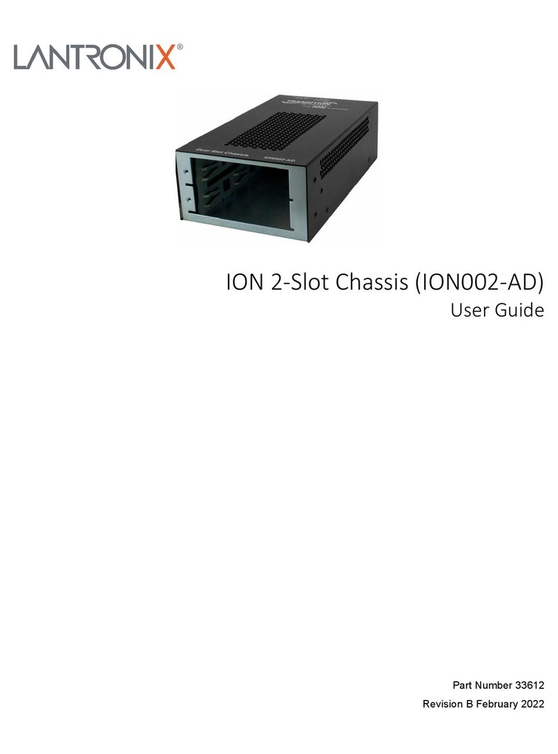
Lantronix ION219 Series User manual

ION219-x
ION 19-Slot Chassis
Install Guide
Part Number 33412
Revision E August 2023

Lantronix ION219-x Install Guide
33412 Rev. E https://www.lantronix.com/ 2
Intellectual Property
© 2022, 2023 Lantronix, Inc. All rights reserved. No part of the contents of this publication may be transmitted or
reproduced in any form or by any means without the written permission of Lantronix.
Lantronix is a registered trademark of Lantronix, Inc. in the United States and other countries. All other
trademarks and trade names are the property of their respective holders.
Patented: https://www.lantronix.com/legal/patents/; additional patents pending.
Warranty
For details on the Lantronix warranty policy, go to our web site at http://www.lantronix.com/support/warranty.
Contacts
Lantronix Corporate Headquarters
48 Discovery, Suite 250
Irvine, CA 92618, USA
Toll Free: 800-526-8766
Phone: 949-453-3990
Fax: 949-453-3995
Technical Support
Online: https://www.lantronix.com/technical-support/
Sales Offices
For a current list of our domestic and international sales offices, go to the Lantronix web site at
www.lantronix.com/about/contact.
Disclaimer
All information contained herein is provided “AS IS.” Lantronix undertakes no obligation to update the information
in this publication. Lantronix does not make, and specifically disclaims, all warranties of any kind (express,
implied, or otherwise) regarding title, non-infringement, fitness, quality, accuracy, completeness, usefulness,
suitability, or performance of the information provided herein. Lantronix shall have no liability whatsoever to any
user for any damages, losses and causes of action (whether in contract or in tort or otherwise) in connection with
the user’s access or usage of any of the information or content contained herein. The information and
specifications contained in this document are subject to change without notice.
Revision History
Rev
Date
Description
2/16/10
A
Initial release for ION219-x 19-Slot Chassis.
3/25/11
B
Added DC power supply technical content.
1/28/20 C
Add ION219-AAMB, IONPS-A-R1, IONPS-D-R1, S3221-1040-T, PS 25138, DoC and
MTBF, update power supply and contact info, and change format. Update to reflect UL
and cUL.
3/10/22
D
Initial Lantronix rebrand.
8/9/23 E
Update IEC 60950-1 to IEC 62368-1. Add IEC 60417-6042 (2010-11) and IEC 60417-
6172 (2012-09). Add Package Label and Device Label, add note to “Disconnect all power
sources” in English and French, and update Technical Support contact info.

Lantronix ION219-x Install Guide
33412 Rev. E https://www.lantronix.com/ 3
Cautions and Warnings
Definitions
Cautions indicate that there is the possibility of poor equipment performance or potential damage to the
equipment. Warnings indicate that there is the possibility of injury to person.
Cautions and Warnings appear here and may appear throughout this manual where appropriate. Failure to read
and understand the information identified by this symbol could result in poor equipment performance, damage
to the equipment, or injury to persons.
Cautions
Caution: Do not ship or store devices near strong electrostatic, electromagnetic, magnetic, or radioactive fields.
Caution: When handling chassis Devices (NIDs) observe electrostatic discharge precautions. This requires proper grounding
(i.e., wear a wrist strap).
Caution: Copper based media ports, e.g., Twisted Pair (TP) Ethernet, USB, RS232, RS422, RS485, DS1, DS3, Video Coax, etc.,
are intended to be connected to intra-building (inside plant) link segments that are not subject to lightening transients or
power faults. They are not to be connected to inter-building (outside plant) link segments that are subject to lightening.
Caution: Do not install the NIDs in areas where strong electromagnetic fields (EMF) exist. Failure to observe this caution
could result in poor NID performance.
Caution: Read the installation instructions before connecting the chassis to a power source. Failure to observe this caution
could result in poor performance or damage to the equipment.
Caution: Only trained and qualified personnel should install or perform maintenance on the device. Failure to observe this
caution could result in poor performance or damage to the equipment.
Caution: Do not let optical fibers come into physical contact with any bare part of the body since they are fragile, and
difficult to detect and remove from the body.
Caution: Do not bend any part of an optical fiber/cable to a diameter that is smaller than the minimum permitted according
to the manufacturer’s specification (usually about 65 mm or 2.5 in)!

Lantronix ION219-x Install Guide
33412 Rev. E https://www.lantronix.com/ 4
Warnings
Warning: Use of controls, adjustments, or the performance of procedures other than those specified herein may result in
hazardous radiation exposure.
Warning: Visible and invisible laser radiation when open. Do not look into the beam or view the beam directly with optical
instruments. Failure to observe this warning could result in an eye injury or blindness.
Warning: DO NOT connect the power supply module to external power before installing it into the chassis. Failure to
observe this warning could result in an electrical shock or death.
Warning: Select mounting bracket locations on the chassis that will keep the chassis balanced when mounted in the rack.
Failure to observe this warning could allow the chassis to fall, resulting in equipment damage and/or possible injury to
persons.
Warning: Do not work on the chassis, connect, or disconnect cables during a storm with lightning. Failure to observe this warning
could result in an electrical shock or death.
See Electrical Safety Warnings on page 28 for Electrical Safety Warnings translated into multiple languages.
Disconnect all power sources.
This device has or supports more than one power source (e.g., different voltages/frequencies or as redundant
power). For the removal of all power from the device, please be aware of the following per IEC 60417-6042
(2010-11) and IEC 60417-6172 (2012-09):
Caution: Shock hazard
Caution: Disconnect all power sources
Débranchez toutes les sources d’alimentation.
Cet appareil possède ou prend en charge plus d’une source d’alimentation (p. ex., différentes tensions/fréquences ou
comme alimentation redondante). Pour la suppression de toute alimentation de l’appareil, veuillez tenir compte des
dispositions suivantes conformément aux normes CEI 60417-6042 (2010-11) et CEI 60417-6172 (2012-09) :
: Mis en garde : Risque de choc
Attention : Débranchez toutes les sources d’alimentation Attention : Débranchez toutes les sources d’alimentation
FCC warning
This equipment has been tested and found to comply with the limits for class A devices, pursuant to part 15 of
the FCC rules. These limits are designed to provide reasonable protection against harmful interference in a
commercial installation. This equipment generates, uses, and radiates radio frequency energy; therefore, if not
installed and used in accordance with the instructions in this document, the device could cause harmful
interference with radio communications. Operation of this equipment in a residential area is likely to cause
harmful interference; all customers will be required to correct the interference problem at their expense.

Lantronix ION219-x Install Guide
33412 Rev. E https://www.lantronix.com/ 5
Contents
1Introduction and Description ..........................................................................................................................7
Product Description ................................................................................................................................................7
Features..................................................................................................................................................................7
Ordering Information...............................................................................................................................................8
ION219-x Chassis Specifications ...........................................................................................................................9
IONPS-x Power Supply Specifications ................................................................................................................ 10
About this Manual ................................................................................................................................................ 10
Related Manuals and Online Help....................................................................................................................... 10
Unpacking............................................................................................................................................................ 11
2Site Preparation ............................................................................................................................................. 12
Chassis Management Methods ........................................................................................................................... 12
Chassis Rear ....................................................................................................................................................... 13
3Installation ...................................................................................................................................................... 14
Cautions............................................................................................................................................................... 14
Safety Considerations.......................................................................................................................................... 14
Lifting Safety .................................................................................................................................................... 14
Electrical Safety ............................................................................................................................................... 14
Site Requirements ............................................................................................................................................... 15
AC Power......................................................................................................................................................... 15
Plant Wiring ..................................................................................................................................................... 15
Site Environment ............................................................................................................................................. 15
Equipment Racks............................................................................................................................................. 15
Installation Procedures ........................................................................................................................................ 16
Installing the Chassis....................................................................................................................................... 16
Tabletop Installation......................................................................................................................................... 16
Rack Installation .............................................................................................................................................. 16
Rack Mount Ears ............................................................................................................................................. 16
Rack Installation Procedure............................................................................................................................. 18
Grounding Lugs ............................................................................................................................................... 18
Grounding Path................................................................................................................................................ 19
Ground Installation........................................................................................................................................... 20
Chassis Slide-In Cards (SICs) and IONMM Installation ...................................................................................... 20
Chassis Power LEDs ........................................................................................................................................... 21
Power Indicator LEDs ...................................................................................................................................... 21
Powering the ION219-x chassis .......................................................................................................................... 22
4Network Connectivity .................................................................................................................................... 23
Connecting Chassis SICs to the Network............................................................................................................ 23

Lantronix ION219-x Install Guide
33412 Rev. E https://www.lantronix.com/ 6
SICs to Network Connections.......................................................................................................................... 23
Chassis Daily Operation .................................................................................................................................. 23
SIC Monitoring ................................................................................................................................................. 23
Network Management.......................................................................................................................................... 23
Firmware and Applications .............................................................................................................................. 23
5Troubleshooting ............................................................................................................................................ 24
Introduction .......................................................................................................................................................... 24
Label Information ................................................................................................................................................. 25
Record Model and System Information ............................................................................................................... 25
Compliance Information....................................................................................................................................... 26
UK Declaration of Conformity .............................................................................................................................. 28
EU Declaration of Conformity .............................................................................................................................. 29
North America and EU Declaration of Conformity ............................................................................................... 30
Electrical Safety Warnings................................................................................................................................... 31
Appendix A Cable Specification and Connectors......................................................................................... 32
RJ45 Cable .......................................................................................................................................................... 32
Coax Cable and BNC Connectors....................................................................................................................... 33
USB (Universal Serial Bus) ................................................................................................................................. 34
Cable Shield Grounding ...................................................................................................................................... 34
Fiber Cables ........................................................................................................................................................ 35
Fiber Connectors ................................................................................................................................................. 35
Figures
Figure 1: ION219-x Chassis .......................................................................................................................................8
Figure 2: Unpacking................................................................................................................................................. 11
Figure 3: ION219-x Chassis Front........................................................................................................................... 12
Figure 4: ION219-x Chassis Rear View................................................................................................................... 13
Figure 5: Unsafe Lifting Techniques........................................................................................................................ 14
Figure 6: Rack Mount Ear Installation Positions...................................................................................................... 16
Figure 7: ION219-x Rack Mount Ear Installation ..................................................................................................... 17
Figure 8: Rack Mounting ......................................................................................................................................... 18
Figure 9: Chassis Grounding Hardware .................................................................................................................. 19
Figure 10: Grounding the Chassis........................................................................................................................... 20
Figure 11: Power Supply LEDs ............................................................................................................................... 21
Figure 12: RJ45 Pinouts .......................................................................................................................................... 32
Figure 13: Coax Cable and BNC Coax Connector Ends......................................................................................... 33
Figure 14: USB Peripheral and Cable Ends............................................................................................................ 34
Figure 15: Simplex Fiber Optic Equipment Cable ................................................................................................... 35
Figure 16: Fiber Optic Cable Connector Ends ........................................................................................................ 35

Lantronix ION219-x Install Guide
33412 Rev. E https://www.lantronix.com/ 7
1 Introduction and Description
Product Description
The ION219-x is an intelligent, high-density, multi-protocol system supporting a variety of network interface
devices. Designed for both carrier class and enterprise network applications where multiple points of fiber
integration and secure network management of the fiber interface devices is essential. An end-to-end fiber
integration solution can be achieved by pairing the modules in a high density ION chassis with the modules in
another ION chassis, an ION stand-alone, or a Lantronix’ Point System™ stand-alone device. To take full
advantage of all the features and functions available with the ION Chassis, an ION Management Module
(IONMM) is required. The IONMM connects to the chassis backplane and communicates with the individual
cards in the ION Chassis. Each slide-in-module for the ION Chassis has specific features and functions that are
controlled via the IONMM. A network administrator can configure, monitor, and troubleshoot ION slide-in-
modules remotely via the IONMM.
Features
Access Methods
•Web-browser: Access the ION Management Module using a standard web browser such as Internet Explorer
or Mozilla Firefox.
•Command Line Interface (CLI): CLI access can be done via telnet remotely or via the local console port on
the ION Management Module.
•SNMP: Since the ION platform is based on public MIBs you can easily manage the ION with a standard
network management system (NMS) such as SNMPc, HPOV or any other standard SNMP platform.
Security Features
When the optional management module is used, the following security features are available, allowing you to
control access to the ION Chassis via the ION Management Module. Ensuring that only authorized personnel can
view and change the settings to the slide-in-modules.
•Management VLAN
•SSL
•SSH
•802.1x
•SNMPv1, v2, and v3
Key Management Features
•Variety of management access methods including; telnet, web, SNMP
•Single slot design allows for more slide-in-modules to be inserted in the ION Chassis
•Management VLAN
•Based on Public MIBs
•Two 10/100 Ethernet interfaces
•USB console port
•Syslog
•TFTP upgrade/backup of slide-in-modules
•Import/Export configuration files in human readable / editable format
•Multiple community strings

Lantronix ION219-x Install Guide
33412 Rev. E https://www.lantronix.com/ 8
The ION219-x is shown below:
Figure 1: ION219-x Chassis
Ordering Information
These ION219-x chassis standard product and options are available:
Product Number
Description
ION219-A
19-Slot Chassis for the ION Platform, AC Powered.
ION219-D
19-Slot Chassis for the ION Platform, DC Powered.
ION219-AAMB 19-Slot Chassis for the ION Platform with (2) AC power supplies and (1) ION
Management Module
Accessories (sold separately)
IONMM
Management Module for the ION Chassis.
IONPS-A
Redundant AC Power Supply for 19-Slot ION Chassis.
IONPS-D
Redundant -48VDC Power Supply for 19-Slot ION Chassis.
IONPS-A-R1
Redundant AC Power Supply for ION219 Chassis.
IONPS-D-R1
Redundant -48VDC Power Supply Module for ION19 Chassis.
WMBC-2RU Wall mount brackets for 2RU Chassis.
IONRE-23 ION Rack Mount Ears.
IONFP
ION Blank face plate (required for open slots).
Power Cord
(included)
To order the country-specific power cord, add the -xx from the list below to the
end of the SKU; Ex: ION219-A-xx, where -xx = Country Code: -NA = North
America, -LA = Latin America, -EU = Europe, -UK = United Kingdom, -SA = South
America, -JP = Japan, -OZ = Australia, -BR = Brazil. Note: Only for ION219-A and
ION219-AAMB.
SFPs
Lantronix offers a full line of small form factor pluggable (SFP) transceivers and
passive coarse wave division multiplexing (CWDM) filters. See the Lantronix SFP
page for details.

Lantronix ION219-x Install Guide
33412 Rev. E https://www.lantronix.com/ 9
ION219-x Chassis Specifications
The ION219-x chassis was designed to meet these standards:
Slots
19 Slots in front for ION slide in-cards and 2 Slots in rear for power supply modules.
IEEE Standards
IEEE 802.3™-2000
Unit LEDs
Power On LED for each installed power supply module.
Certifications UL Listed, EN55032, EN55035, CE Mark, UKCA, FCC Class A, CISPR Class A
Power
Two open bays for ION power supply modules, supporting Universal Input 100 –
240 VAC, or -48VDC rated at 200 watts max output. Note: Power supply module
supplies +12VDC maximum to each slot in the chassis. Only one power supply
module is required to power the chassis and the installed modules, the optional
second power supply module provides redundancy for instant fail-over.
Power Consumption
up to 150 watts
Power Source
IONPS-A, IONPS-D, IONPS-A-R1, IONPS-D-R1
Dimensions
Width: 17.0” (430mm) x Depth: 15.8” (401mm) x Height: 3.5” (89mm).
Weight
19 lbs. [8.6 kg] (ION219 shipping weight).
Operating Temp.
0° ~ +50 °C
Storage Temp.
-40° ~ +85 °C
Altitude
0-10,000 feet
Operating Humidity 5% to 95% (non-condensing).
Compliance UL/cUL listed, EN55022, EN55024, CE Mark, FCC Class A, CISPR Class A.
MTBF*
ION219-A: Greater than 23,570 MIL-HDBK-217F Hours.
Greater than 64,800 Bellcore Hours.
ION219-D: Greater than 42,900 MIL-HDBK-217F Hours.
Greater than 118,000 Bellcore Hours.
ION219-A-R1: Greater than 23,570 MIL-HDBK-217F Hours.
Greater than 64,800 Bellcore Hours.
ION219-D-R1: Greater than 42,900 MIL-HDBK-217F Hours.
Greater than 118,000 Bellcore Hours.
Warranty
Limited Lifetime Warranty
* MTBF calculations done with these settings: Prediction Method: MIL-HDBK-217F Parts Count. Environment:
GB, Ground Benign. Temperature 25°C.

Lantronix ION219-x Install Guide
33412 Rev. E https://www.lantronix.com/ 10
IONPS-x Power Supply Specifications
See the related IONPS-x power supply manual for specifications and standards.
About this Manual
This manual provides instructions on how to install and configure the ION219-x Chassis to accommodate various
types of ION slide-in cards (SICs) and power supplies.
Related Manuals and Online Help
A printed documentation card is shipped with each device. Context-sensitive Help screens, as well as
cursor-over-help (COH) facilities are built into the Web interface.
For Lantronix Documentation, Firmware, App Notes, etc. go to https://www.lantronix.com/technical-support/.
Note that this manual provides links to third party web sites for which Lantronix is not responsible.
For SFP manuals see Lantronix SFP webpage.
Note that this manual provides links to third part web sites for which Lantronix is not responsible.
Other ION System and related device manuals are listed below.
•ION Management Module (IONMM) Install Guide, 33420 and User Guide, 33457
•ION System x323x Remotely Managed NID User Guide, 33432
•ION Systems CLI Reference Manual, 33461
•ION x222x & x32xx Multi-port NIDs Installation Guide, 33433
•ION219 Cxx1x NID Installation Guides, 33414 - 33417
•ION Dry Contact Relay (DCR) Kit Install Guide, 33422
•IONPS-A AC Power Supply Install Guide, 33423, 33464
•IONPS-D DC Power Supply Install Guide, 33424
•IONPS-A-R1 AC Power Supply User Guide, 33614
•IONPS-D-R1 DC Power Supply User Guide, 33707
•ION ADP Install Guide, 33413
•SFP manuals (product specific)
•Release Notes (firmware version specific)
Note: Information in this document is subject to change without notice. All information was deemed accurate
and complete at the time of publication. This manual documents the latest software/firmware version. While all
examples may not display the latest version number, all the descriptions and procedures reflect the latest
software/firmware version, noted in the Record of Revisions above. Transition Networks is now Lantronix. Some
products/firmware items are still in process of being re-branded and may still reflect the Transition Networks
name/logo.

Lantronix ION219-x Install Guide
33412 Rev. E https://www.lantronix.com/ 11
Unpacking
1. Carefully unpack all ION219-x contents.
2. Verify receipt of all ION219-x components. Contact your sales representative if any items are missing.
3. Place the ION219-x and related materials near the install location.
4. Save the ION219-x shipping carton and packing materials for possible future use.
Figure 2: Unpacking

Lantronix ION219-x Install Guide
33412 Rev. E https://www.lantronix.com/ 12
2 Site Preparation
The ION219-x 19-Slot Chassis contains a fixed 100Mbs full duplex bus with point to-point connection with all
endpoints, which greatly improves data bandwidth and response time. Each endpoint in the system (Slide-In
Card (SIC), Backplane Controller (BPC), power supply (PS) and Agent) has a dedicated port on a 24-Port non-
blocking, full-bandwidth 100Mbps Ethernet switch, supporting simultaneous traffic between all endpoints.
You can achieve an end-to-end fiber integration solution by paring the modules in a high-density ION chassis
with the modules in another ION chassis. To take full advantage of all the features and functions available with
the ION chassis, an ION Management Module (IONMM) is required. The IONMM connects to the chassis
backplane and communicates with the individual installed SICs. The IONMM controls the specific features and
functions of each SIC.
The ION219-x allows the network administrator to connect various copper and fiber-optic network media.
The ION219-x chassis provides installation space for up to 19 single-slot SICs. See Figure 3 below.
Figure 3: ION219-x Chassis Front
Chassis Management Methods
The ION219-x chassis can be managed and monitored via the IONMM Management Module using the following:
•Web-browser: Access the ION Management Module using a standard web browser such as Internet
Explorer, Google Chrome, or Mozilla Firefox.
•Command Line Interface (CLI): CLI access can be done via telnet remotely or via the local console port on
the ION Management Module.
•SNMP: Since the ION platform is based on public MIBs you can easily manage the ION with a standard
network management system (NMS) such as SNMPc, HPOV or any other standard SNMP platform.

Lantronix ION219-x Install Guide
33412 Rev. E https://www.lantronix.com/ 13
Chassis Rear
The ION219-x is equipped with an AC power supply or an optional DC power supply installed in one of its rear
slots. An extra installation space is available for an optional (AC or DC) power supply for redundancy purposes.
See Figure 4 below.
Figure 4: ION219-x Chassis Rear View

Lantronix ION219-x Install Guide
33412 Rev. E https://www.lantronix.com/ 14
3 Installation
This chapter describes ION219-x cautions/warnings, site requirements, installation, and setup.
Cautions
Caution: Install the ION219-x chassis so that the airflow around it is not restricted. Failure to observe this
caution could result in performance problems or damage to the contents of the chassis.
Caution: Read the installation instructions before connecting the chassis to a power source. Failure to observe
this caution could result in poor performance or damage to the chassis and its SICs.
Caution: Only trained and qualified personnel should install or replace the ION210-x chassis. Failure to observe
this caution could result in poor performance or damage to the chassis.
Safety Considerations
The following considerations will help to ensure your safety as well as protection of the chassis and its contents
from damage. This list does not contain all the potentially hazardous conditions that could exist at the
installation site, so exercise caution at all times.
•Always unplug all power cords before installing or removing the chassis.
•Keep the chassis area clear and dust free during and after installation.
•Keep tools and chassis components away from walk areas.
•DO NOT place containers containing liquid on top of the chassis.
Lifting Safety
Even though the ION219-x chassis weights less than twenty (20) pounds, use proper lifting to move the chassis
about. Keep your back straight and lift with your legs, not your back. If you need to bend down to lift the chassis,
bend at the knees, not at the waist to reduce potential for straining your lower-back muscles. See Figure 5
below.
Figure 5: Unsafe Lifting Techniques
Electrical Safety
Follow these basic guidelines when working with any electrical equipment:
•Disconnect all power and external cables before installing or removing the chassis.
•Do not work alone when potential hazard conditions exist.
•Never assume that power has been disconnect from the circuit—always check.
•Carefully examine your work area for possible hazards such as wet floors, ungrounded power extension
cables, and missing safety ground.
WARNING: Do not work on the chassis, connect, or disconnect cables during a storm with lightning activity.
Failure to observe this warning could result in an electrical shock or death.

Lantronix ION219-x Install Guide
33412 Rev. E https://www.lantronix.com/ 15
Site Requirements
To assure normal operation and avoid unnecessary maintenance, plan the site configuration, and prepare the
site before installation. After installation, make sure that the site maintains an ambient temperature of 0°C to
+50°C (+32°F to +122°F).
Caution: To prevent the chassis from overheating, do not operate it in an area that exceeds the maximum
recommended ambient temperature +50°C (+122°F).
AC Power
See the related ION Power Supply user Guide for input voltage, current, power, and other operating ranges.
Caution: The power outlet must be located near the equipment and must be easy to access.
WARNING: If the voltage indication on the label is different from the power outlet voltage, DO NOT plug the
chassis into that receptacle. A voltage mismatch can cause equipment damage and may pose a fire hazard.
WARNING: Take care not to overload the circuit that supplies power to the chassis. Failure to observe this
warning could result in a fire.
WARNING: The chassis must be grounded. Make sure that the host is connected to earth ground during normal
use. Failure to observe this warning could result in electrical shocks.
Plant Wiring
The following guidelines consider the plant wiring and cabling at your site. When planning the location of the
chassis, consider the distance limitations of signaling, electromagnetic interference (EMI), and connector
capability.
When wires are run from any significant distance in an electromagnetic field, interference can occur between
the field and the signal on the wires.
If wires exceed recommended distances, or if wires pass between buildings, consider the potential for lightning
strikes. The electromagnetic pulse (EMP) caused by lighting or other high-energy phenomena can easily couple
enough energy into unshielded cable to destroy electronic devices.
Site Environment
The chassis can operate as a standalone system or can be mounted in a rack in a secure wiring closet. It requires
a dry, clean, well-ventilated environment. An internal fan system pulls air from the front of the system and
exhausts it through the chassis rear. The flow of ambient air must be maintained to ensure proper operation.
If the airflow is blocked or restricted, or if the intake air is too warm, an over temperature condition will occur.
To ensure normal operation and avoid unnecessary maintenance, plan your site configuration, and prepare your
site before installation. After installation, make sure the site maintains an ambient temperature of 0°C to +50°C
(+32° to +122°F). Keep the area around the chassis as dust free as possible.
Equipment Racks
Multiple chassis can be rack-mounted with little or no clearance above and below them. However, when
mounting the chassis in a rack with other equipment or when placing it on the floor with other equipment
located close by, ensure that the exhaust from other equipment does not blow into the intake of the chassis.

Lantronix ION219-x Install Guide
33412 Rev. E https://www.lantronix.com/ 16
Installation Procedures
Installing the Chassis
The ION219-x chassis can be installed in a standard 19-inch rack or on a table, shelf, or other stable surfaces.
Tabletop Installation
The ION219-x chassis comes with nine (9) rubber feet for installation on a table or other flat, stable surface in a
well-ventilated area. If tabletop installation is desired, remove the rubber feet from the card and place them on
the bottom of the chassis. Distribute the feet so that the chassis is level when placed upright.
Rack Installation
The Maximum Recommended Ambient Temperature (TMRA) for the ION219-x chassis is +50°C (+122°F). When
installing the ION219-x chassis in a closed or multiunit rack assembly, the operating ambient temperature of the
rack environment could be greater than room ambient.
Note: Reliably grounding is required for rack-mounted equipment. Power supply connections other than direct
connections to the branch circuit (e.g., use of power strips) should be employed.
WARNING: Select mounting bracket locations on the chassis that will keep the chassis balanced when mounted
in the rack. Failure to observe this warning could allow the chassis to fall, resulting in equipment damage and/or
possible injury to persons.
Rack Mount Ears
The ION219-x chassis has facilities that allow the installation of the rack mount ears on the chassis, either flush
against the front or recessed from the front of the rack as shown in Figure 6 below.
Figure 6: Rack Mount Ear Installation Positions

Lantronix ION219-x Install Guide
33412 Rev. E https://www.lantronix.com/ 17
Installing Rack Mount Ears
Note: Installation rack-mount-ear mounting screws (cover-to-frame screws, see Figure 7 below) are provided.
Rack mount “screws” and “clip nuts” are NOT provided.
To install the ION219-x chassis rack mount ears, do the following:
1. Determine the preferred alignment of the chassis into the rack.
2. Using a Phillips screwdriver, remove the six (6) cover-to-frame screws (three on each side of the chassis).
See Figure 7 below.
3. Align the mounting bracket in the selected installation position, as shown in Figure 7 below.
Figure 7: ION219-x Rack Mount Ear Installation
4. Using a Phillips screwdriver, install the three (3) screws to mount the rack mount ear to the side of the
chassis. See Figure 7 above.
5. Repeat steps 2 and 4 for the second rack mount ear.

Lantronix ION219-x Install Guide
33412 Rev. E https://www.lantronix.com/ 18
Rack Installation Procedure
To install the chassis in a rack, do the following:
1. Locate four (4) mounting screws (not provided) and optional clip-nuts (not provided) for each chassis to be
installed.
2. Carefully position and align the chassis to the mounting holes in the rack, as shown in Figure 8 below.
3. Install two (2) screws through the right bracket into the right mounting rail and two (2) screws through the
left bracket into the left mounting rail, using the clip nuts (not provided) to secure the chassis to the rack.
Figure 8: Rack Mounting
Grounding Lugs
The ION219-x chassis comes equipped with grounding lugs, which are provided for a grounding conductor wire
terminated with a two-hole, compression-type grounding connector. The grounding wire must be a copper
conductor (not provided).

Lantronix ION219-x Install Guide
33412 Rev. E https://www.lantronix.com/ 19
Grounding Path
The electrical conducting path from the chassis to ground must:
•Flow via the grounding lugs to the Common Bonding Network (CBN) for telecom installations, or to an
alternate approved grounding system (if required) for non-telecom installations.
•Be sufficiently low in impedance to conduct fault currents likely to be present on the chassis.
•Enable proper operation of any over-current protection devices.
Fasten the two-hole compression-type grounding connector to the grounding lugs with the provided Kepsnut
fasteners. See Figure 9 below.
Figure 9: Chassis Grounding Hardware

Lantronix ION219-x Install Guide
33412 Rev. E https://www.lantronix.com/ 20
Ground Installation
To ground the ION219-A chassis, do the following:
1. Obtain one (1) properly terminated, grounding conductor (12 AWG copper wire gauge or larger) with a two-
hole, compression-type, grounding connector. Note the manufacturer's applied torque required for the
connector.
2. Attach the grounding conductor to the chassis by placing the two-hole, compression-type connector onto the
grounding lugs and then fasten with the appropriate lock-washers and lug nuts at the proper torque. See Figure
10 below.
3. Attach the opposite end of the properly terminated grounding conductor to the Common Bonding Network
(CBN) for telecom installations, or to an approved grounding system (if required) for non-telecom installations.
Figure 10: Grounding the Chassis
Chassis Slide-In Cards (SICs) and IONMM Installation
Refer to the user guide for each SIC for specific information on the cables, connectors, and LED indicators of the
individual SICs.
Table of contents
Other Lantronix Chassis manuals
Popular Chassis manuals by other brands

Enterasys
Enterasys SecureStack C2RPS-CHAS2 installation guide

ICP Electronics
ICP Electronics EC-1040 user manual

Enterasys
Enterasys S8-Chassis-POE4 Hardware installation guide

Overland Storage
Overland Storage SnapServer DX2 Upgrade instructions

Miranda
Miranda DENSITE series Guide to installation and operation

Vox Technologies
Vox Technologies RACK-2300 user manual