Vox Technologies RACK-2300 User manual

RACK-2300 CHASSIS
USER’S MANUAL

Copyright Notice
This document and product is copyrighted, January 2001, by ICP Electronics Inc. All
rights are reserved. No part of this manual may be reproduced, copied, or translated
without prior notice to ICP Electronics Inc.
The information provided in this document is for reference only. We do not assume
any responsibility arising out of the application of the products. This manual is
subject to change without any notice.
RACK-2300, ICP are trademark of ICP Electronics Inc.

Table of Contents
Chapter 1 Product Information
1.1 General Information
1.2 Product Specifications
1.3 Dimensions
Chapter 2 System Setup
2.1 Front Panel of RACK-2300
2.2 LP-01 Control Panel of RACK-2300
2.3 Rear Panel of RACK-2300
2.4 Removing the chassis cover
2.5 Backplane Installation
2.6 Disk Drives Installation
2.7 Power Supply Installation
Appendix A Passive Backplane
Appendix B Exploded Diagram
Appendix C Power Supply

Chapter 1 Product Information
1.1 General Information
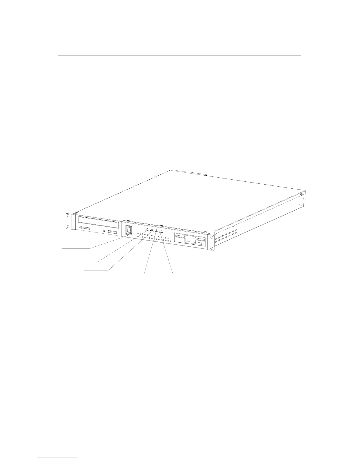
RACK-2300 IPC chassis is a rugged PC/AT compatible computer designed for the
factory floor and other Industrial harsh environment. RACK-2300 features 2 slots
Passive Backplanes and high reliability ACE-1010A series power supply.
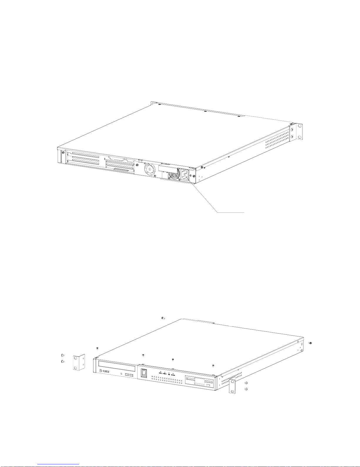
The chassis can easily be installed on 19" Rack or Desktop with the supplied
brackets.
1.2 Product Specifications
General specification
- Construction : Heavy-duty steel
- Disk Driver : One 5.25” Removable Disk Drive, one FDD Disk Driver and
one 3.5” HDD
- Cooling Fan : Dual Ball bearing fans
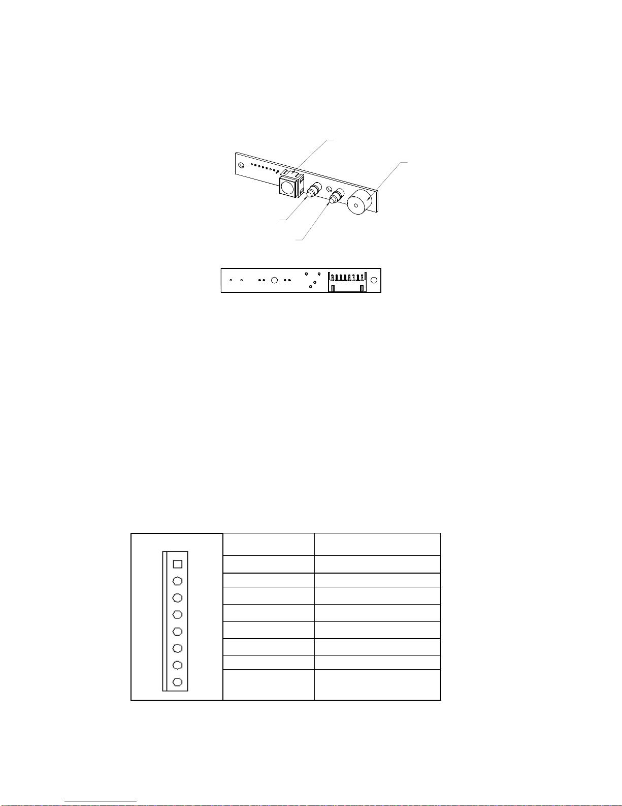
- Indicator : Two LEDs to monitor the status of HDD and Power Supply
- Dimension : 550x 440 x 44 ( W x D x H )
- I/O Port : One USB Port (Type A)
Passive Backplanes (Optional)
PCI-2SD2 – 2 slot ISA/PCI bus Backplane (VER:1.3)
Power Supply
Standard equipped power supply for the RACK-2300 is : ACE-1010A.

Working Environment
- Operating Temperature : 0~40°C
- Relative Humidity : 5~95% Relative
- Vibration : 5-17Hz, 0.1” double amplitude displacement
17-640Hz, 1.5G acceleration peak to peak
- Shock : 10G acceleration peak to peak
- Safety approval : meet CE, FCC
Cooling Fan
3 front ball bearing cooling fans.
Drive Capacity
One 5.25” removable disk driver, one 3.5” FDD and one 3.5” HDD

1.3 Dimensions
RESET POWER BUZZERHDD
44
32
483
466
550 19
440

Chapter 2 Installation Procedure
The following set up procedures are provided to assist you in installing the system
unit, please follow the steps below:
2.1 Front Panel of RACK-2300
POWER LED
RESET SWITCH
HDD LED BUZZER
POWER SWITCH

2.2 LP-01 Control Panel of RACK-2300
LP-01 Panel
BZ1: BUZZER
D1:POWER LED
D2: System HDD LED
SW1: RST system reset button
CN1:
Pin # FUNCTION
1 SPEAKER (+)
2 SPEAKER (-)
3 POWER LED (-)
4POWERLED(+)
5 HDD LED(-)
6 HDD LED(-)
7 RESET (1)
1
88 RESET (2)
13
4
25678Pin
BUZZER
HDD LED(RED)
POWER LED(GREEN)
RESET SWITCH

2.3 Rear Panel of RACK-2300
2.4 Removing the chassis cover
The cover is mounted by eight screws on the top of the chassis, remove them
and slide the cover to the rear of the chassis. Figure below shows how to
remove the chassis cover.
AC INPUT

2.5 Backplane Installation
Figure below illustrates how to install the backplanes on the RACK-2300
Please plug the connector of ACE-1010A to the Backplane IP-2SD2.
PCI-2SD2
STEP1
STEP2
BACKPLANE:PCI-2SD2
HDD LED(RED)
BUZZER
POWER LED(GREEN)
RESET SWITCH
SUPPLY
POWER
ACE-1010A

2.6 Disk Drives Installation
1.Open the upper disk drive cover.
2.Mount the drive rails on the side of FDD
3.Attach the FDD to the bracket with four screws and connect FDD cable
&powercabletotheFDD.
4.Directly fix the 3.5” HDD with four screws into chassis and connect a
40-pin flat cable & power cable to it.

2.7 Power Supply Installation

APPENDIX A PASSIVE BACKPLANES
7.50
7.00
154.00
23.00
30.50
7.00

APPENDIX B EXPLODED DIAGRAM

APPENDIX C Power Supply
REFERENCE DOCUMENTS
The subject power supply will meet the EMI requirements and obtain main safety
approvals
as following:
- FCC Part 15 Subpart J, Class ‘B’ 115 Vac operation.
- CISPR 22 Class ‘B’ 230 Vac operation.
SAFETY
- NEMKO EN 60950
- TUV EN60950 OR VDE EN60950
- CSA 22.2 NO. 234 LEVEL 3
- IEC 950
- UL 1950
- CE
PHYSICAL REQUIREMENTS
CONNECTOR SPECIFICATIONS
PIN1 NC PIN16 +5V
PIN2 +5Vsb PIN17 +3.3V
PIN3 +5Vsb PIN18 +3.3V
PIN4 GND PIN19 +3.3V
PIN5 GND PIN20 +3.3V
PIN6 GND PIN21 -5V
PIN7 GND PIN22 -12V
PIN8 GND PIN23 +3.3Vsb
PIN9 GND PIN24 +12V
PIN10 GND PIN25 +12V
PIN11 +5V PIN26 +12V
PIN12 +5V PIN27 +12V
PIN13 +5V PIN28 P.G
PIN14 +5V PIN29 PS-ON
PIN15 +5V PIN30 NC
ELECTRICAL REQUIREMENTS
OUTPUT RATING
Output Nominal Regulation Ripple/Noise Min Max
1 +3.3V 5% 50mV 0.3A 12.0 A
2+5V 5% 50mV 1.5A 16.0 A
3+12V 5% 120mV 0.1A 5.0 A
4-5V 5% 100mV 0 A 0.3A
5 -12V 10% 120mV 0 A 0.8 A
6+5VSB 5% 100mV 0 A 2.0A
+5V, +3.3V and +12V total output not exceed 148W.

The +3.3V and +5V total output shall not exceed 100watts, and the total output for
this subject power supply is 170 watts. Ripple and noise measurements shall be
made under all specified load conditions through a single pole low pass filter with
20MHz cutoff frequency. Outputs shall bypassed at the connector with a 0.1uF
ceramic disk capacitor and a 10uF electrolytic capacitor to simulate system loading.
LOAD CAPACITY SPECIFICATIONS
The cross regulation defined as follows, the voltage regulation limits DC include DC
Output ripple & noise.
LOAD STM. +3.3V +5V +12V -5V -12V
ALL MAX HHHHH 12.0A 14.0A 4.0A 0.3A 0.8A
+5V MAX
other MIN LHLLL 0.3A 16.0 A 0.1A 0A 0A
+3.3V MAX
other MIN HLLLL 12.0 A 1.5 A 0.1A 0A 0A
+12V MAX
other MIN LLHLL 0.3A 3.0 A 5.0A 0A 0A
ALL MIN LLLLL 0.3 A 1.5 A 0.1A 0A 0A
HOLD-UP TIME (@FULL LOAD)
115V / 60Hz : 17 mSec. Minimum.
230V / 50Hz : 17 mSec. Minimum.
OUTPUT RISE TIME
(10% TO 90% OF FINAL OUTPUT VALUE, @FULL LOAD)
115V-rms or 230V-rms + 5Vdc : 20ms Maximum
OVER VOLTAGE PROTECTION
+5V
dc output: +5.58Vdc minimum, + 6.82Vdc maximum
+ 3.3Vdc output: +3.5Vdc minimum, + 4.5Vdc maximum
SHORT CIRCUIT PROTECTION
Output short circuit is defined to be a short circuit load of less than 0.1 ohm.
POWER GOOD SIGNAL
TTL signal asserted (low state) : less than 0.5V while sinking 10mA.
TTL signal asserted (high state): greater than 4.75V while sourcing 500uA.
High state output impedance: less or equal to 1Kohm from output to common.
POWER GOOD @ 115/230V,FULL LOAD 100 –500mSec.
POWER FAIL @115/230V, FULL LOAD 1 mSec. minimum

OUTPUT TRANSIENT LOAD RESPONSE
+5Vvdc:
IA: 16.0amps
IB: 12.0amps
Voltsvariation: 400mVmax(p-p)
Settingtime: 10 msmax
+12Vvdc:
IA: 5.0amps
IB: 3.75amps
Voltsvariation: 450mVmax(p-p)
Settingtime: 10 msmax
INPUT ELECTRICAL SPECIFICATIONS
VOLTAGE RANGE
PARAMETER MIN. NOM. NAX. UNITS
V-in Range 95 115/230 264 V-rms
INPUT FREQUENCY
NOMINAL FREQUENCY
115V 60Hz
230V 50Hz
INRUSH CURRENT
(Cold start – 25 deg. C)
115V 60 Amps - peak
230V 90 Amps - peak
INPUT LINE CURRENT
115V 5.0 Amps – rms maximum
230V 3.0 Amps – rms maximum
EFFICIENCY
General 115 VAC @Full Load 68% minimum
230 VAC @Full Load 68% minimum

Energy Star
115VAC @min Load 56% minimum
In the low-power Energy Star state, the AC input power is limited to 30W.
ENVIRONMENTAL REQUIREMENTS
The power supply will be compliant with each item in this specification for the
following
Environmental conditions.
TEMPERATURE RANGE
Operating 0 to +40 deg. C
Storage -20 to +80 deg. C
HUMIDITY Operating 5 –95% RH, Non-condensing
Storage 5 –95% RH, Non-condensing
VIBRATION
Vibration Operating – Sine wave excited, 0.25 G maximum acceleration, 10-250 Hz
swept at one octave / min.
SHOCK
Storage - 40G, 11 mSec. half-sine wave pulse in both directions on three
mutually perpendicular axes.
Operating - 10G, 11mSec. half-sine wave pulse in both directions on three
mutually perpendicular axes.
Table of contents