LAQUA LAQUA-EC1100 User manual

Benchtop Conductivity Meter
LAQUA-EC1100
Instruction Manual
CODE:GZ0000427794

I
Preface
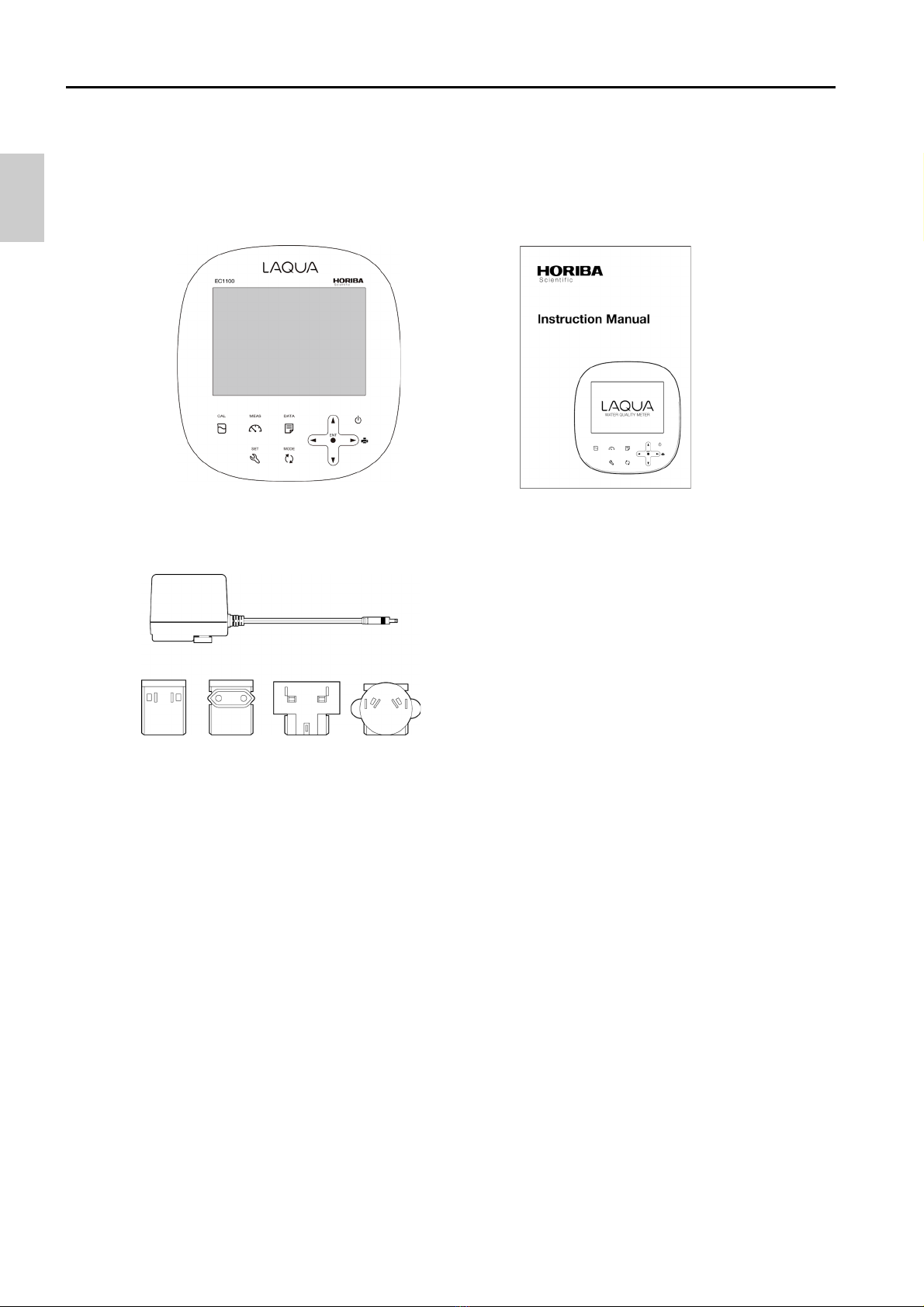
This manual describes the operation of the Benchtop Conductivity Meter LAQUA-
EC1100.
Be sure to read this manual before using the product to ensure proper and safe
operation of the product. Also safely store the manual so it is readily available whenever
necessary.
Product specifications and appearance, as well as the contents of this manual are
subject to change without notice.
■Warranty and responsibility
HORIBA, Ltd. warrants that the Product shall be free from defects in material and
workmanship and agrees to repair or replace free of charge, at option of HORIBA, Ltd.,
any malfunctioned or damaged Product attributable to responsibility of HORIBA, Ltd. for
a period of two (2) yearsfrom the delivery unless otherwise agreed with a written
agreement. In any one of the following cases, none of the warranties set forth herein
shall be extended;
・Any malfunction or damage attributable to improper operation
・Any malfunction attributable to repair or modification by any person not authorized
by HORIBA, Ltd.
・Any malfunction or damage attributable to the use in an environment not specified in
this manual
・Any malfunction or damage attributable to violation of the instructions in this manual
or operations in the manner not specified in this manual
・Any malfunction or damage attributable to any cause or causes beyond the
reasonable control of HORIBA, Ltd. such as natural disasters
・Any deterioration in appearance attributable to corrosion, rust, and so on
・Replacement of consumables
HORIBA, LTD. SHALL NOT BE LIABLE FOR ANY DAMAGES RESULTING FROM ANY
MALFUNCTIONS OF THE PRODUCT, ANY ERASURE OF DATA, OR ANY OTHER
USES OF THE PRODUCT.
■Trademarks
・Microsoft, Windows, Windows Vista are registered trademarks or trademarks of
Microsoft Corporation in the United States and other countries.
Other company names and brand names are either registered trademarks or trademarks
of the respective companies. (R), (TM) symbols may be omitted in this manual.
CODE:I20050170003200635702GZ0000427794
January, 2016 2016 HORIBA, Ltd.

Check items
II
■Items in package
After opening the package, check for damage on the instrument and that the standard
accessories (see below) all exist.
If damage or defects are found on the product, contact your dealer.
Instrument Instruction manual
(this book)
AC adapter
USA Europe U.K. Australia

Regulations
III
■EU regulations
●Conformable standards
This equipment conforms to the following standards:
●Installation environment
This product is designed for the following environment.
・Overvoltage Category II
・Pollution degree 2
●Information on disposal of electrical and electronic
equipment and disposal of batteries and accumulators
The crossed out wheeled bin symbol with underbar shown on the product or
accompanying documents indicates the product requires appropriate treatment,
collection and recycle for waste electrical and electronic equipment (WEEE) under the
Directive 2012/19/EU, and/or waste batteries and accumulators under the Directive
2006/66/EC in the European Union.
The symbol might be put with one of the chemical symbols below. In this case, it satisfies
the requirements of the Directive 2006/66/EC for the object chemical.
This product should not be disposed of as unsorted household waste.
Your correct disposal of WEEE, waste batteries and accumulators will contribute to
reducing wasteful consumption of natural resources, and protecting human health and
the environment from potential negative effects caused by hazardous substance in
products.
Contact your supplier for information on applicable disposal methods.
EMC: EN61326-1
Class B, Basic electromagnetic environment
Safety: EN61010-1
RoHS: EN50581
9. Monitoring and control instruments
Warning: This product is not intended for use in industrial environments. In an
industrial environment, electromagnetic environmental effects may
cause the incorrect performance of the product in which case the
user may be required to take adequate measures.

Regulations
IV
■FCC rules
Any changes or modifications not expressly approved by the party responsible for
compliance shall void the user's authority to operate the equipment.
●WARNING
This equipment has been tested and found to comply with the limits for a Class A digital
device, pursuant to part 15 of the FCC Rules. These limits are designed to provide
reasonable protection against harmful interference when the equipment is operated in a
commercial environment. This equipment generates, uses, and can radiate radio
frequency energy and, if not installed and used in accordance with the instruction
manual, may cause harmful interference to radio communications.
Operation of this equipment in a residential area is likely to cause harmful interference in
which case the user will be required to correct the interference at his own expense.
■Korea certification
●
■Taiwan battery recycling mark

For your safety
V
■Hazard classification and warning symbols
Warning messages are described in the following manner. Read the messages and
follow the instructions carefully.
●Hazard classification
●Warning symbols
This indicates an imminently hazardous situation which, if
not avoided, will result in death or serious injury. This is to
be limited to the most extreme situations.
This indicates a potentially hazardous situation which, if
not avoided, could result in death or serious injury.
This indicates a potentially hazardous situation which, if
not avoided, may result in minor or moderate injury. It may
also be used to alert against unsafe practices.
Description of what should be done, or what should be followed
Description of what should never be done, or what is prohibited

For your safety
VI
■Safety precautions
This section provides precautions for using the product safely and correctly and to
prevent injury and damage. The terms of DANGER, WARNING, and CAUTION indicate
the degree of imminency and hazardous situation. Read the precautions carefully as it
contains important safety messages.
●Instrument and electrode
WARNING
Do not use an unspecified AC adapter.
Otherwise, it may heat up or be ignited resulting in a fire or an accident.
Do not disassemble or modify the instrument.
Otherwise, it may heat up or be ignited resulting in a fire or an accident.
Fire
• For your safety, make sure to unplug the power plug from the electrical
outlet when not in use.
• Clear dust on the power plug periodically (a few times a year).
If the power supply cord is left plugging into the electrical outlet for a long
period of time, electrical tracking may occur due to dust and moisture, and it
may result in an ignition or a fire.
Fire or electric shock
• Do not bundle the power supply cord during use.
• Do not damage the power supply cord nor apply an excessive load to it,
such as bending and stretching it repeatedly, putting a heavy thing on it.
• If it can not be plugged into an electrical outlet firmly, stop use of the
power supply cord.
If may result in overheating, a fire, an electrical shock, or breakdown.
CAUTION
Broken glass
Broken glass may cause injury. The outer tube and tip of an electrode are
made of glass. Handle them with care.
Do not use the RS-232C or USB communication and the AC adapter under
wet or humid conditions. Otherwise, it may cause a fire, electric shock, or
breakage.

For your safety
VII
■Product handling information
●Operational precautions
・Only use the product including accessories for their intended purpose.
・Do not drop, crash, or give any physical impact on the instrument.
・Do not immerse the instrument into alcohol, organic solvent, strong acid, strong
alkaline, or the like. The instrument body contains ABS resin, acrylic resin, and some
rubber parts.
・If the instrument is dropped into water or gets wet, wipe it using soft cloth. Do not heat
to dry it with a hair-dryer (or the like).
・Use fingers to press the operation keys or the touch panel. Do not use a hard object
like a metal stick or rod.
・Be careful not to let water into the instruction inside. The instrument is not water-proof.
・To disconnect an electrode or interface cable, hold the connector and pull it off. If you
pull at the cable, it may cause a breakage.
・The touch panel is capacitance-type. Make sure to turn OFF the power before
cleaning the panel. If you wipe it with the power ON, it may cause instrument
malfunction.
・RS-232C or USB communication between the instrument and a personal computer
(referred to as PC in the rest of this document) may fail because of environmental
conditions, such as (radio/electromagnetic) noise.
・Make sure to use the provided power supply cable to power this product.
●Environmental conditions for use and storage
・Temperature: 0°C to 45°C
・Humidity: under 80% in relative humidity and free from condensation
Avoid the following conditions.
・Strong vibration
・Direct sunlight
・Corrosive gas environment
・Close to an air-conditioner
・Direct wind
・Dusty environment
●Transportation
When transporting the instrument, repackage it in the original package box. Otherwise, it
may cause instrument breakage.

For your safety
VIII
●Disposal
・Standard solution used for the calibration must be under neutralized before the
disposal.
・When disposing of the product, follow the related laws and/or regulations of your
country for disposal of the product.

Manual information
IX
■Description in this manual
This interprets the necessary points for correct operation and notifies the important
points for handling the product.
This indicates the part where to refer for information.
This indicates reference information.
Note
Reference
Tip

Contents
X
Preface ................................................................................... I
■Items in package..................................................................II
■Hazard classification and warning symbols .................... V
■Safety precautions............................................................. VI
■Product handling information ......................................... VII
■Description in this manual................................................ IX
Part names and basic operation......................................... 1
■Names of each part..............................................................2
●Instrument ................................................................................... 2
●Display ......................................................................................... 4
●Operation key.............................................................................. 5
■Basic operation....................................................................6
●Function layer ............................................................................. 6
●Changing the operation mode................................................... 8
●Changing the measurement parameter .................................... 9
●Entering numeric values ............................................................ 9
●Saving measurement data in the internal memory................ 10
Measurement...................................................................... 11
■Preparation.........................................................................12
●Confirmation before starting measurement........................... 12
●Turning ON the instrument ...................................................... 13
●Connecting an electrode.......................................................... 14
■Conductivity measurement...............................................15
●Setting the instrument.............................................................. 16
●Performing conductivity calibration ....................................... 26
●Performing measurement ....................................................... 29
●Saving measured values.......................................................... 30

Contents
XI
●Printing measured values in the measurement mode...........30
Using various functions .................................................... 31
■Data functions....................................................................32
●Displaying saved data ..............................................................32
●Deleting all saved data .............................................................33
■Measurement settings.......................................................34
●Displaying the latest calibration data......................................34
●Changing the calibration method ............................................35
●Deleting calibration data ..........................................................36
■Temperature setting ..........................................................38
●Calibrating temperature sensor...............................................38
■General settings ................................................................39
●Setting the auto stability and the auto hold function ............39
●Resetting to factory default settings.......................................41
●Performing test printing of the printer unit ............................42
●Setting automatic print .............................................................43
●Setting password ......................................................................44
■Other settings ....................................................................46
●Printing measured values and calibration data .....................46
●Transferring saved data to a PC ..............................................49
●Operating the instrument from an external device ................50
Maintenance ....................................................................... 51
●Contact for maintenance ..........................................................51
●Maintenance and storage of the instrument...........................51
●Environmental conditions for storage ....................................51
●Maintenance and storage of the conductivity cell .................52
How to resolve errors or troubles .................................... 53

Contents
XII
■When an error message appears .....................................53
●ERROR No.0001 Memory error ............................................. 53
●ERROR No.0006 Maximum calibration points exceeded ... 53
●ERROR No.0009 Printer error ............................................... 54
●ERROR No.0010 Memory full ................................................ 54
●ERROR No.0011 Cell constant is out of range .................... 54
■Troubleshooting ................................................................55
●The indicated value fluctuates ................................................ 55
●The response is slow ............................................................... 55
●The indicated value does not change/No response .............. 56
●The measured value is outside the display range................. 56
●Repeatability of the measured value is poor ......................... 56
●Nothing appears when the power is turned ON..................... 57
●Part of the display is missing .................................................. 57
Appendix............................................................................. 59
■Main specifications............................................................59
●Table of conductivity cell range .............................................. 61
●Table of conductivity cell range (resistivity range) ............... 62
■Functions............................................................................62
■Instrument default settings...............................................63
■Technical note....................................................................64
●Conductivity standard values at various temperatures........ 64
■Options ...............................................................................65

1
Part names and basic operation
This section describes the name of each part and the main role, function, and basic
operation method of each part.
■Names of each part...................................................................... 2
●Instrument.............................................................................................. 2
●Display.................................................................................................... 4
●Operation key ........................................................................................ 5
■Basic operation............................................................................ 6
●Function layer........................................................................................ 6
●Changing the operation mode ............................................................. 8
●Changing the measurement parameter............................................... 9
●Entering numeric values....................................................................... 9
●Saving measurement data in the internal memory .......................... 10

Names of each part
2
■Names of each part
●Instrument
Operation key
Electrode stand
Display
CH2 measurement electrode (G) connector
CH2 temperature electrode (T) jack
AC adapter jack Printer or RS-232C connector
Connector for USB communication with a PC

Names of each part
3
• Identification of manufacturing date
Manufacturing date can be identified from MFG No. described in the ID label on the
backside of the instrument.
Third number from the left in the MFG No. indicates manufacturing year.
Forth alphabet from the left in the MFG No. indicates manufacturing month.
The alphabet is assigned to month according to the table below.
Ex.: ID: AA6A0000 means the device manufactured in 2016 January.
JAN FEB MAR APR MAY JUN JUL AUG SEP OCT NOV DEC
AB C D E F G H J K L M

Names of each part
4
●Display
HOLD
Calibration
Measurement
Error No.,
Data No.,
Date
Status icon
Measurement
Temperature
USB icon
Data memory icon
Printer connecting icon
Electrode status icon
indicator
parameters
points unit

Names of each part
5
●Operation key
This instrument employs capacitance switches. You can not operate them with thick
gloves. Operate them with bare hands or thin rubber gloves.
Tip
"ERROR No." icon is displayed on the screen when pressing the invalid key.
Key Name Function
CAL key Enters the calibration mode.
Performs the calibration.
MEAS key Enters the measurement mode.
Releases the fixed measurement value in auto hold mode.
DATA key Enters the data mode.
SET key Enters the setting mode.
Cancels the setting values of the setting mode.
MODE key Switches the measurement items.
▲key
▼key
Increases the values.
Decreases the values.
Switches the setting item.
Switches the channels.
key Changesnumber of digits, selects functions.
Prints out the measurement values. ( key)
ENTER key
Settlement, execution
Saves the measurement data in the measurement mode.
Starts/stops automatic data memory.
POWER key
Turns ON or OFF the power.
Press the POWER key for one second or longer to turn ON
or OFF the power.

Basic operation
6
■Basic operation
●Function layer
The function layer of the data mode and setting mode is shown as below.
"dX" and "PXX" indicates the program number which is shown in the screen of the
instrument.
• Data mode
Screen Layer Description
d1: DAT.OUT Saved data display
d2: DAT.CLR Deletion of saved data

Basic operation
7
• Setting mode
Screen Layer Description
P1: COND Conductivity measurement settings
P11: CELL Cell constant setting
P12: UNIT Selection of unit:
S/cm, S/m, mS/cm FIX
P13: CAL.DAT Calibration data display
P14: AT. CAL Selection of auto calibration,
manual calibration
P15: CAL.CLR Deletion of calibration data
P16: TC Temperature conversion setting:
0.00%/°C to 10.00%/°C
P17: TC REF Reference temperature setting:
15°C to 30°C
P2: TDS TDS measurement settings
P21: TYPE Selection of TDS calculation
method: Linear, 442, En, NaCl
P3: SALT Salinity measurement settings
P31: UNIT Selection of unit: %, ppt
P32: TYPE Selection of salinity calculation
method: NaCl, SEAWATER
P4: TC Temperature settings
Selection of temperature
conversion: ATC, MTC
P5: GEN General settings
P51: MEAS Selection of auto hold type:
auto stability, auto hold
P52: RESET Initialization of settings
P53: PRINT Test print
P54: AT. PRN Automatic print setting
P55: PASS Password
Table of contents
Other LAQUA Measuring Instrument manuals
Popular Measuring Instrument manuals by other brands

Dwyer Instruments
Dwyer Instruments DPG-200 Series Specifications-installation and operating instructions

Schaller
Schaller humimeter PM3 user manual

PeakTech
PeakTech 9040 Operation manual

OPTOKON
OPTOKON PM-240-MTP instruction manual

Berthold
Berthold LB 444 operating manual

Sole Digital
Sole Digital TFL300 Installation and user manual