BURK Technology BTU-4 Owner's manual

BTU-4 & Sensors
Installation and Operation Manual

Copyright © 2017 Burk Technology, Inc.
Rev. D
Table of Contents
Introduction...................................................................................................................................1
Sensors.........................................................................................................................................1
BTO –Outdoor Sensor..............................................................................................................1
BTI –Indoor Sensor..................................................................................................................1
BTS –Stack Sensor..................................................................................................................1
Installation.....................................................................................................................................2
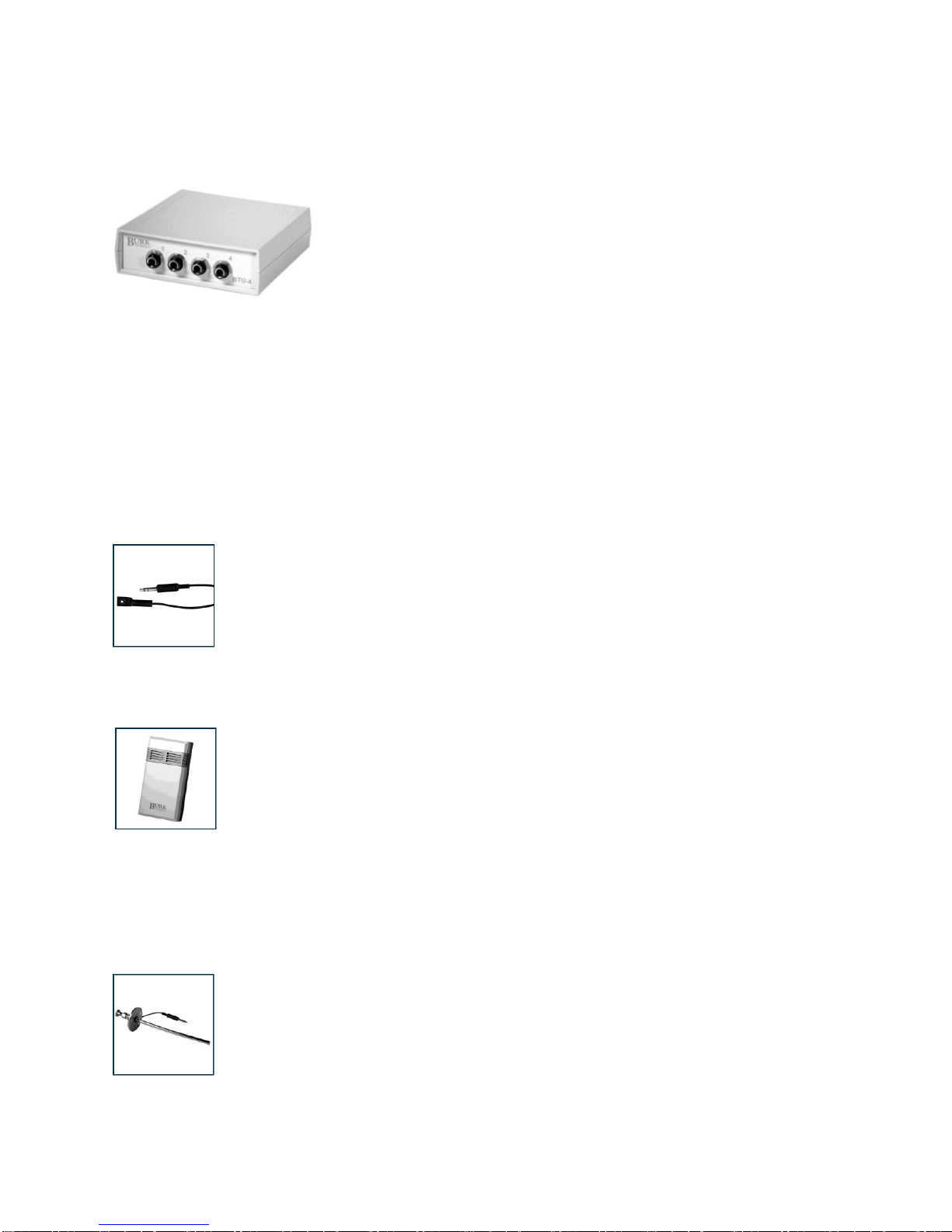
BTU‐4 –Burk Temperature Unit................................................................................................2
BTO –Outdoor Sensor..............................................................................................................2
BTI –Indoor Sensor..................................................................................................................3
BTS –Stack Sensor..................................................................................................................3
Remote Control Setup ..................................................................................................................4
ARC Plus...................................................................................................................................4
ARC Solo...................................................................................................................................4
ARC-16......................................................................................................................................4
GSC3000/VRC2500..................................................................................................................4
Specifications................................................................................................................................5
Dimensions:...............................................................................................................................5
Power:.......................................................................................................................................5
Inputs:........................................................................................................................................5
Outputs:.....................................................................................................................................5
Sensor Temperature: ................................................................................................................5
Cable Length:............................................................................................................................5
BTO Outdoor Sensor:................................................................................................................5
BTI Indoor Sensor: ....................................................................................................................5
BTS Stack Sensor:....................................................................................................................5
Getting Help..................................................................................................................................6
Warranty .......................................................................................................................................6

BTU-4 Installation and Operation Manual Rev D
1
Introduction
The BTU‐4 Burk Temperature unit supports up to four independent
temperature sensors, and provides a low voltage output that tracks
linearly with the AC line voltage.
Each temperature output supplies 10mV per degree Fahrenheit or
Centigrade, based on the type of sensor installed.
The BTU‐4 is supplied with:
•One AC power adapter
•One BTO Fahrenheit temperature sensor
•One 6‐terminal plug for connection to monitoring equipment
Sensors
BTO –Outdoor Sensor
The BTO is included with the BTU‐4 system, and is intended for general purpose
monitoring of equipment or ambient temperatures.
The BTO is attached to 15’ of shielded cable with a stereo phone type connector.
The sensor has a mounting ring and gasket to accommodate #6 or #8 hardware. The
sensing elements are sealed for added protection from dirt and moisture.
BTI –Indoor Sensor
The BTI is tailored for monitoring ambient temperatures within a room, while
maintaining a polished appearance.
The BTI is housed in a 2 5/8” x 5” enclosure with air vents to facilitate sensing of the
environment.
15’ of shielded cable is provided with a stereo phone type connector on one end. The BTI has a large, easy
to connect barrier strip that accommodates flat or Phillips type screwdrivers.
BTS –Stack Sensor
The BTS is designed for sensing heat within the air ducting of your equipment.
The BTS is attached to 15’ of shielded cable with a stereo phone type connector.
The sensor is mounted in the tip of a 3/8” diameter chrome tube. The supplied
mounting hardware consists of a base and a compression fitting to allow the sensor to
be secured at variable depths. This allows the installer to locate the sensor up to 9 1/2”
from the equipment wall, well within the airflow being monitored.

BTU-4 Installation and Operation Manual Rev D
2
Installation
BTU‐4 –Burk Temperature Unit
Temperature sensors (BTO, BTI, and BTS) use a 1/4” phone plug for easy connection to the BTU‐4. Each
sensor input is numbered for reference. The four inputs are independent, and can be used in any order.
Connect the output ofthe BTU‐4 to your remote control equipment using the provided 6‐terminal plug.
Connections are labeled on the end panel.
Pin
Usage
1
Sample from temperature sensor #1
2
Sample from temperature sensor #2
3
Sample from temperature sensor #3
4
Sample from temperature sensor #4
5
Sample from AC line monitor
6
Ground connection for all samples
The BTU‐4 is powered by an external AC power adapter. The supplied adapter accepts 120VAC input, and
provides 12VAC to the power input jack of the BTU‐4.
BTO –Outdoor Sensor
1. Attach the ring of the BTO with the supplied #6 sheet metal screw, or use any existing post, hook or
machine screw.
2. Route the cable to the BTU‐4.
3. Disconnect the AC adapter from the BTU‐4.
4. Plug the connector of the BTO into one of the four available input jacks on the BTU‐4.
5. Connect the output sample pin associated with the appropriate input jack from the BTU‐4 to the
remote control equipment.
6. Plug the AC adapter into the BTU‐4.

BTU-4 Installation and Operation Manual Rev D
3
BTI –Indoor Sensor
1. Position the back half of the enclosure against the surface where the BTI will mount.
2. Using the enclosure as a template, mark reference circles at each of the two mounting slots
and the cable entry point.
3. Set aside the enclosure and drill a hole at the cable entry location.
4. Mount two screws in the wall, or into wall anchors, leaving at least 1/8” from the wall to the
underside of the screw head.
5. Test fit the enclosure back half against the wall. Check for a secure fit, still allowing for
removal of the BTI from the wall.
6. From the location of the BTU‐4, route the BTI cable through the wall and the rear of the
enclosure. The length of the cable does not affect calibration, and it may be extended as
required.
7. Attach the cable to the terminals on the front half of the BTI:
Terminal
Usage
1
Red
2
Black
3
Shield/Drain
4
No Connection
8. Secure the two halves of the BTI using the 3/4” screws, being careful not to over tighten them.
9. Place the BTI against the wall and secure it to the mounting screws.
10. Disconnect the AC adapter from the BTU‐4.
11. Plug the connector of the BTI into one of the four available input jacks on the BTU‐4.
12. Connect the output sample pin associated with the appropriate input jack from the BTU‐4 to
the remote control equipment.
13. Plug the AC adapter into the BTU‐4.
BTS –Stack Sensor
1. Select a location on the equipment ducting that is flat and able to support the weight of the BTS and
its mounting hardware. Make certain there are no obstructions on the inside of the ducting or
cavity.
2. Using the mounting base as a template, mark the location of all mounting holes.
3. Drill or cut a hole approximately 3/4” in diameter for the BTS probe.
4. Thread the 3/8” brass pipe fitting onto the base, and secure the base to the surface using the
supplied sheet metal screws.
5. Insert the BTS into the brass mount and secure it with the locking nut. Be certain to not tighten
excessively, as this may deform the compression sleeve. Check for a secure fit, still allowing for
adjustment of the probe depth.
6. Disconnect the AC adapter from the BTU‐4.
7. Plug the connector of the BTS into one of the four available input jacks on the BTU‐4.
8. Connect the output sample pin associated with the appropriate input jack from the BTU‐4 to the
remote control equipment.
9. Plug the AC adapter into the BTU‐4.

BTU-4 Installation and Operation Manual Rev D
4
Remote Control Setup
ARC Plus
Note: The meter type must be set to “Degree” and the voltage range set to “-10 to 10”.
Configure the ARC Plus to show one decimal place (000.0). No calibration is necessary. Please
refer to your ARC Plus manual for detailed instructions.
ARC Solo
Note: The meter type must be set to “Degree” and the voltage range set to “-10 to 10”.
Configure the ARC Solo to show one decimal place (000.0). No calibration is necessary. Please
refer to your ARC Solo manual for detailed instructions.
ARC-16
Note: The meter type must be set to “MV” (pre-5.x firmware) of “DEG” (5.x or later firmware).
Configure the ARC-16 to show the decimal point one digit to the left (if true input valve = 700
[MV/DEG], displayed value = 70.0 [MV/DEG]). No calibration is necessary. Please refer to your
ARC-16 manual for detailed instructions on moving the decimal point display location.
GSC3000/VRC2500
Note: The meter type should be set to “-5 to +5” to allow for negative and positive temperature
readings.
Calibrate the desired channel(s) to read the actual temperature (if true input value = 0.70 [Volts],
calibrate value = 70 [Degs]). The displayed value must be static (no fluctuations) during
calibration. Please refer to your GSC300 or VRC2500 manual for detailed instructions on
calibrating metering channels.

BTU-4 Installation and Operation Manual Rev D
5
Specifications
Dimensions:
1.5” (3.81cm) H
5” (12.70cm) W
5.25” (13.34cm) D
Power:
12VAC wall adapter (provided)
Inputs:
4 1/4” phono jacks for use with BTI, BTO and BTS sensors
Outputs:
6-terminal plug providing four temperature samples and one AC line sample
Sensor Temperature:
LM34 (Fahrenheit) maximum temperature 300oF, LM35 (Celsius) maximum temperature 149oC.
Cable Length:
Maximum recommended cable length is 50’.
BTO Outdoor Sensor:
15’ shielded 1/4” phono cable; Mount with #6 or #8 hardware
BTI Indoor Sensor:
2 5/8” x 5” enclosure
BTS Stack Sensor:
15’ shielded 1/4” phono cable; 3/8” chrome tube; Mounting depth up to 9 1/2”

BTU-4 Installation and Operation Manual Rev D
6
Getting Help
For technical support, please email support@burk.com or call our direct technical support line at 978‐
486‐3711. We will be glad to assist you. The technical support office is open Monday – Friday, 9AM to
5PM Eastern Time.
Warranty
Burk Technology, Inc. warrants the BTU‐4, BTO, BTI, and BTS to be free of defects in materials and
workmanship for a period of 24 months from the date of purchase. Equipment will be repaired or replaced
at the option of Burk Technology and returned freight prepaid to the customer. Damage due to abuse or
improper operation or installation of the equipment or caused by fire or flood or harsh environment is
not to be covered by this warranty. Damage in shipping is not the responsibility of Burk Technology. A
return authorization must be obtained before returning any equipment. Materials returned under this
warranty must be shipped freight prepaid and insured in the original shipping carton or suitable substitute
to Burk Technology, Inc., 7 Beaver Brook Road, Littleton, MA 01460. Repairs not covered under this
warranty will be made at prevailing shop rates established by Burk Technology.
THE WARRANTY SET FORTH ABOVE IS IN LIEU OF ALL OTHER WARRANTIES, EXPRESS
OR IMPLIED, INCLUDING BUT NOT LIMITED TO THE WARRANTIES OF
MERCHANTABILITY AND FITNESS FOR A PARTICULAR PURPOSE. BURK TECHNOLOGY,
INC. SHALL NOT BE LIABLE TO ANY PARTY FOR ANY INCIDENTAL, SPECIAL, INDIRECT
OR CONSEQUENTIAL DAMAGES ARISING FROM THE USE OF THIS EQUIPMENT.
Table of contents
Other BURK Technology Measuring Instrument manuals
Popular Measuring Instrument manuals by other brands

Keysight Technologies
Keysight Technologies M9710A Configuration and Measurement Instructions

Magnescale
Magnescale LH71 Series Operation manual

Fluke
Fluke CO-220 Instruktionsblad

EUTECH INSTRUMENTS
EUTECH INSTRUMENTS CyberScan PCD 650 quick guide

Sartorius
Sartorius LMA200PM operating instructions

Keithley
Keithley 630 instruction manual