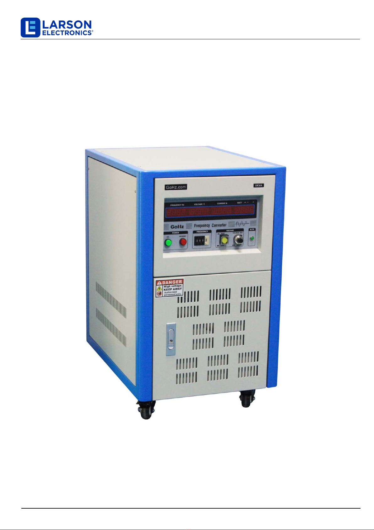
Larson Electronics IND-SFC Series User manual

IND-SFC Series
Larson Electronics, LLC Phone: (877) 348-9680 Fax: (903) 498-3364 www.larsonelectronics.com
Solid-state Frequency Converter
Mobile w/ Wheels
Instruction Manual

Read this user manual before using frequency converter.
Keep this user manual near the frequency converter for reading at any time.
Careful in transporting the frequency converter to avoid impact.
Do not put the frequency converter on uneven or inclined surface.
Do not block the venting holes or slits to keep the frequency converter well-cooling effect, the back of the
frequency converter should keep 10 cm (4 inches) away from the wall.
Double check the frequency converter and power supply specifications are matched and well-wired before
power connection to avoid any careless damage.
Frequency converters have different installations according to different capacities and voltage levels,
choose an appropriate configuration and cable diameter.
Do not overload the frequency converter to prevent the electric shock or cause fires.
Please follow all applicable local and national electrical and building code.
In case of abnormal phenomenon happens, follow this user manual in troubleshooting or contact the
manufacturer.
Please keep frequency converter clean and do not put heavy objects on top of it.
Prevent any liquids and sundries into the frequency converter, in order to avoid poor contact or short
circuit, electric shock,or fire.
Unplug the power cord in stormy weather.
Avoid placing in direct sunlight, raining or humid place.
Keep it away from the source of ignition and heat to prevent overheat.
Unplug the power cord during moving or maintaining the frequency converter.
IND-SFC Series
Safety Information
Larson Electronics, LLC Phone: (877) 348-9680 Fax: (903) 498-3364 www.larsonelectronics.com

Product Features
Frequency converter is suitable for use with resistive, capacitive, inductive and non-linear loads.
Compatible with 50 Hz & 60 Hz input frequency.
Adjustable single phase 0-300v AC, three phase 0-520v AC output voltage.
Adjustable 40.0 to 120 Hz output frequency,customize 499.9Hz.
Precise 4 LED digital display output frequency,voltage, ampere and wattage.
Isolated operation, no harmonic distortion (EMI, EMC).
Pure sine wave output.
IGBT/PWM technology enhances compact size, low noise and high reliability.
Capable to simulate global voltage, frequency power supplies.
Frequency converters are equipped with electronic circuit/instant trip breaker/buzzer alarm for over
voltage, over current, over temperature, output short circuit protection.
Checklist
Every frequency converter has functional testing before leaving factory, the frequency converter is wooden
packaged, includes:
1 unit frequency converter
Operation manual
IND-SFC Series
Larson Electronics, LLC Phone: (877) 348-9680 Fax: (903) 498-3364 www.larsonelectronics.com
①
①
②
③
⑥③
②
⑤
⑤④
④
R S T N G L N G
Single Phase Three Phase to Single Phase
L N G L N G

IND-SFC Series
①
②
⑥③
⑧
⑦
④⑤
R S T N G U V W N G
Three Phase
①Operation Panel
②Input Air-switch
③Output Air-switch
④Input Terminals
⑤Output Terminals
⑥Low/High Voltage Switch (For 30kVA and Above)
⑦Low/High Voltage Indicator (For 3-Phase 3kVA to 20kVA)
⑧Phase/Line Voltage Switch (For 3-Phase 3kVA to 20kVA)
Larson Electronics, LLC Phone: (877) 348-9680 Fax: (903) 498-3364 www.larsonelectronics.com

IND-SFC Series
Wiring Precaution
Whether the capacity of the frequency converter in accordance with your loads.
Whether the frequency converter damaged during transportation, if so, do not connect it to power source.
Shut down power before wiring, check the input voltage before installation.
Make sure the specification of the cable in accordance with the frequency converter before wiring. The
cable diameter should follow the voltage level and capacity of the frequency converter.
Please refer to electrician wiring regulations, or following the "Cable Diameter Reference" table.
Avoid sharing the power switch of the frequency converter with other appliances.
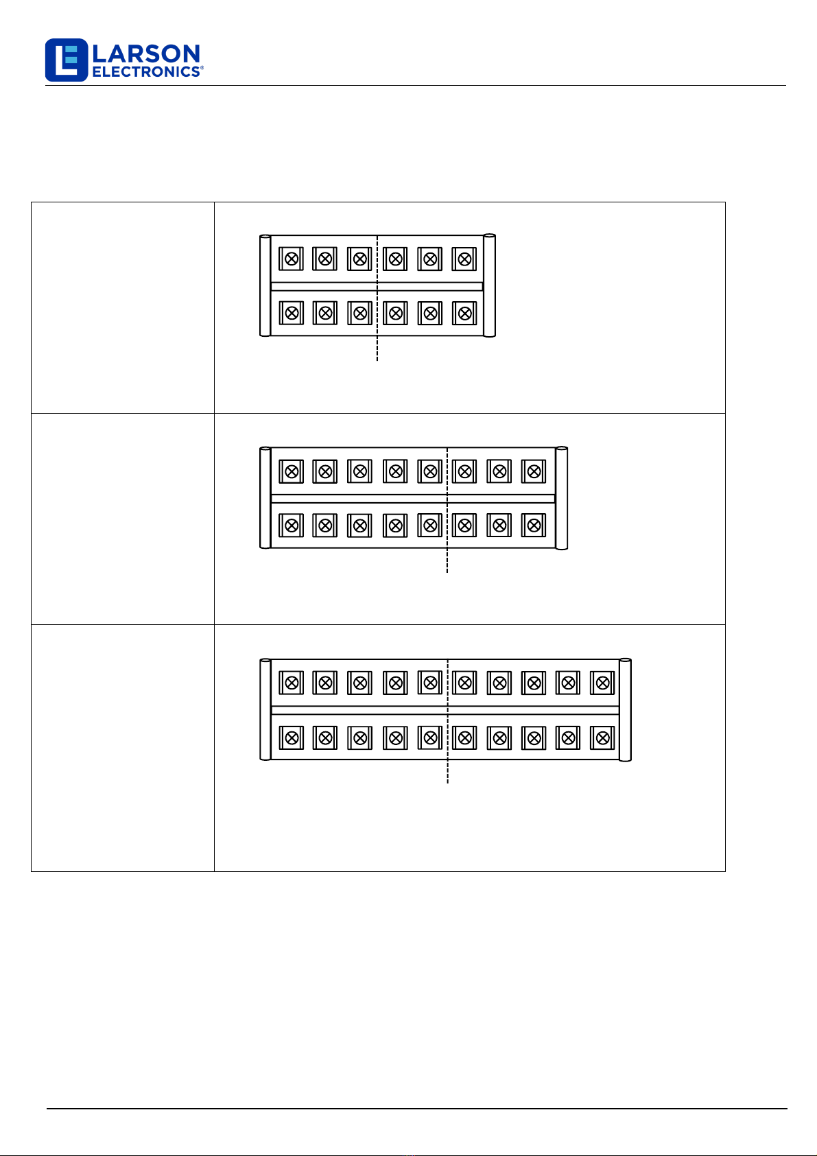
Use O-type wiring terminals, make sure it's well-wired, tighten screws to avoid poor contact and prevent
electric shock.
Make sure the power source is correct to match single phase or three phase frequency converter.
For grounding, refer to the next page.
Make sure all switches on "OFF" status before connecting the frequency converter to power source.
Make sure the power source, frequency converter and loads are matching before power on.
Internal semiconductor components are sensitive to static electricity, be careful in touching the metal
control panel.
Larson Electronics, LLC Phone: (877) 348-9680 Fax: (903) 498-3364 www.larsonelectronics.com
Grounding System
In addition to safety consideration, well-grounded system also can avoid the power system interferes
equipment normal operation.
Ground Cable should be separated with Neutral Cable, unless special applications.
Ground Cable should be 8AWG cable at least or the diameter is basically the same.
Ground Cable is for specified frequency converter only,poor ground will cause interference to other
machines.
Use ground rods in grounding for the best.
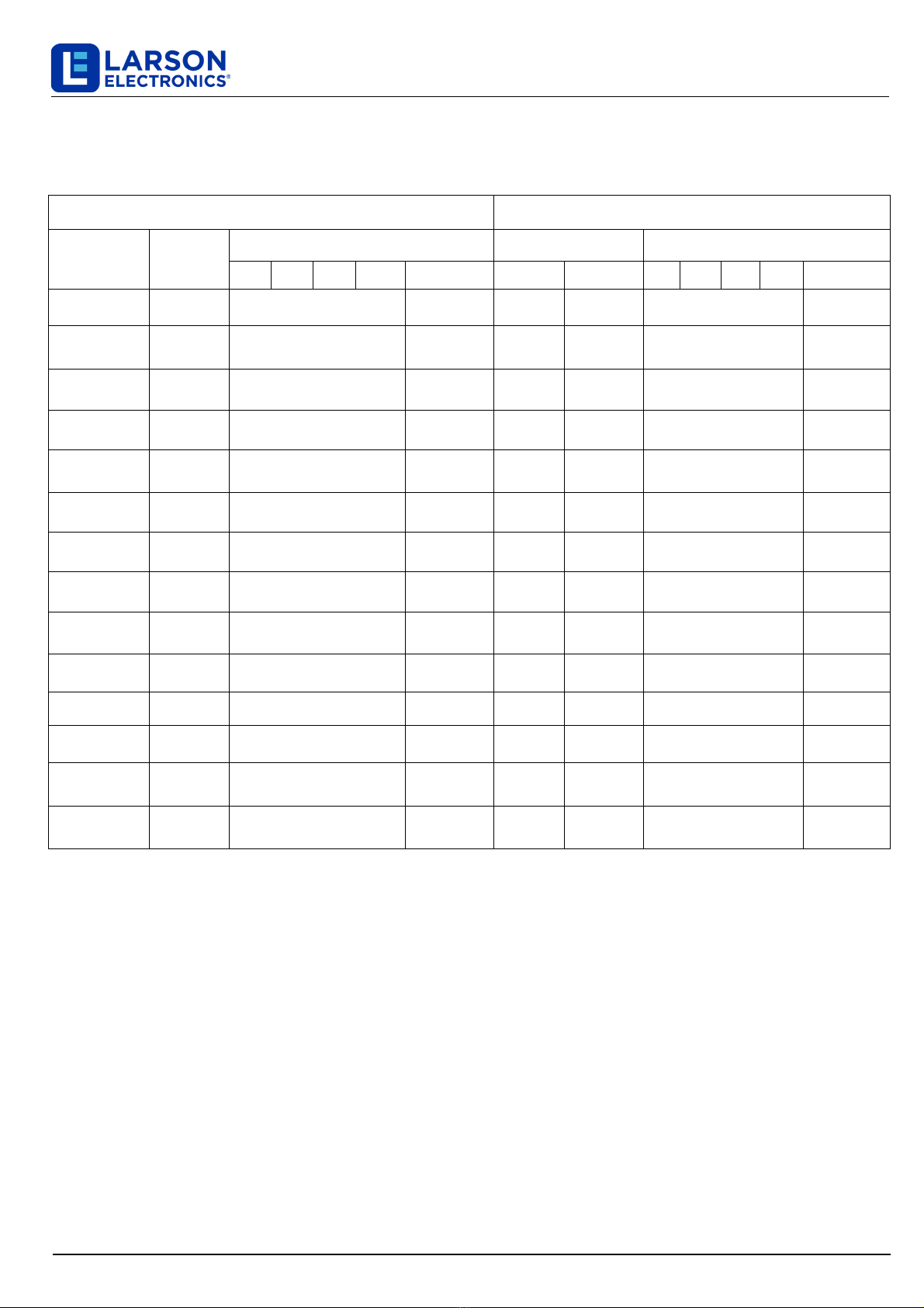
Ground Types:
tem Application
Item Resistance value
1
Low voltage power supply system or high voltage electrical
equipment of three-phase four-wire multi-grounded systems
grounding
10Ωor less
2 Ungrounded high-voltage electrical equipment grounding
system. 25Ωor less
3 Low voltage power supply system of three-phase three-wire
ungrounded system. 50Ωor less
4
1.. round voltage less than 150V is 100Ωor less.
2.. round voltage 151V to 300V is 50Ωor less.
3.. round voltage higher than 301V is 10Ωor less.
1. Low voltage electrical equipment grounding
2. Inner system grounding
3. Frequency converter secondary grounding
4. Low voltage electrical equipment metal body
grounding.

Cable Diameter Reference Table
1Ø 2W / 220V 1Ø 2W / 0-300V
Capacity Input Max. O/P Current Output
L N G ow Hi
LowL L N G
2kVA ≥2.5mm22.5mm216.8A 8.4A ≥2.5mm22.5mm2
3kVA ≥4mm22.5mm225A 12.5 ≥4mm22.5mm2
5kVA ≥6mm26mm241.6A 20.8A ≥6mm26mm2
10kVA ≥10mm210mm283.2A 41.6A ≥16mm210mm2
15kVA ≥16mm210mm2125A 62.5A ≥25mm210mm2
20kVA ≥25mm210mm2166.6A 83.3A ≥35mm210mm2
30kVA ≥35mm210mm2250A 125A ≥50mm210mm2
IND-SFC Series
Larson Electronics, LLC Phone: (877) 348-9680 Fax: (903) 498-3364 www.larsonelectronics.com
3Ø 4W / 380V 1Ø 2W / 0-300V
Capacity Input Max. O/P Current Output
RR S T N G ow HiLowL L N G
10kVA ≥4mm26mm283.2A 41.6A ≥16mm210mm2
15kVA ≥6mm26mm2125A 62.5A ≥25mm210mm2
20kVA ≥6mm26mm2166.6A 83.3A ≥35mm210mm2
30kVA ≥10mm210mm2250A 125A ≥50mm210mm2
45kVA ≥16mm210mm2375A 187.5A ≥75mm210mm2
50kVA ≥16mm210mm2416.6A 208.3A ≥83mm210mm2
60kVA ≥25mm210mm2500A 250A ≥100mm210mm2
75kVA ≥30mm210mm2625A 312.5A ≥150mm210mm2
90kVA ≥35mm210mm2750A 375A ≥180mm210mm2
100kVA ≥50mm210mm2833.3A 416.7A ≥200mm210mm2
120kVA ≥70mm210mm21000A 500A ≥250mm210mm2
150kVA ≥95mm210mm21250A 625A ≥300mm210mm2

3Ø 4W/ 380V 3Ø 4W / 0-520V
Capacity Input Max. O/P Current Output
RR S T N G ow HiLowL UU V W N G
3kVA ≥1.5mm22.5mm28.4A 4.2A ≥2mm26mm2
10kVA ≥4mm22.5mm227.6A 13.8A ≥6mm26mm2
15kVA ≥6mm26mm241.6A 20.8A ≥8mm26mm2
20kVA ≥6mm26mm255.6A 27.8A ≥10mm26mm2
30kVA ≥10mm26mm283.2A 41.6A ≥16mm26mm2
45kVA ≥16mm210mm2125A 62.5A ≥25mm210mm2
60kVA ≥25mm210mm2166.6A 83.3A ≥35mm210mm2
75kVA ≥30mm210mm2208.3A 104.2A ≥42mm210mm2
90kVA ≥35mm210mm2250A 125A ≥50mm210mm2
100kVA ≥50mm210mm2277.7A 138.8A ≥70mm210mm2
120kVA ≥70mm210mm2333.3A 166.6A ≥95mm210mm2
150kVA ≥95mm210mm2416.6A 208.3A ≥120mm210mm2
200kVA ≥120mm210mm2555.5A 277.7A ≥185mm210mm2
300kVA ≥180mm210mm2833.3A 416.6A ≥240mm210mm2
IND-SFC Series
Larson Electronics, LLC Phone: (877) 348-9680 Fax: (903) 498-3364 www.larsonelectronics.com
Note: user can choose different cables according to the input and output conditions, when the input or
output cable length exceeds 20 meters, the cable diameter should be doubled.

Single Phase Input,
Single Phase output.
Three Phase Input,
Single Phase Output.
Three Phase Input,
Three Phase Output. TR S N G U V W N G
Input
R S T N G L N G
L N G L N G
Wiring Terminals
OutputInput
Output
Input
Output
IND-SFC Series
Larson Electronics, LLC Phone: (877) 348-9680 Fax: (903) 498-3364 www.larsonelectronics.com

IND-SFC Series
Larson Electronics, LLC Phone: (877) 348-9680 Fax: (903) 498-3364 www.larsonelectronics.com
Chapter V. Operation Panel
*Some models may differ slightly in layout*

Chapter VI. Operation Guide
Proper operating procedures allow you to use the frequency converter more smoothly and avoid unnecessary
troubles.
1. Make sure the POWER ON switch is on OFF position.
2. Make sure the switches, rotary buttons, displays are not loosen or damaged.
3. Make sure the power supply is matching with the frequency converter specifications (110V, 220V etc.)
before turning the input POWER ON switch to ON position.
4. Set the output frequency by "FREQUENCY SET" switch. Note, press OFF/RESET for setting hundreds
frequency (1xx.x).
5. Choose the Low/High Voltage output voltage according to the loads, for ≤150V change 0-150V (low) and
1-300V (high) base on required voltage.
6. Press to POWER ON switch (ON).
7. Connect loads cable and turn on the AC OUTPUT switch to obtain required standard AC power supplies.
8. Frequency converter has overcurrent (overload), over temperature, short circuit, instantaneous power off
protection and warning indicators. In case of above phenomenon happens, the protection circuit cut off
output immediately and trigger warning buzzer.
9. Press OFF / RESET switch to cut off the output.
Caution: For 30kVA frequency converter (and above), to switch Low/High voltage, if the frequency
converter is connected loads, the frequency converter must be powered off and turn off the output switch
before switching the voltage.
IND-SFC Series
Larson Electronics, LLC Phone: (877) 348-9680 Fax: (903) 498-3364 www.larsonelectronics.com

Chapter VII. Specification
Single Phase Input, Single Phase Output
Capacity 500VA 1kVA 2kVA 3kVA 5kVA 10kVA 15kVA 20kVA
Input Voltage (Optional) 1 Phase 2 Wire: 110V/220V/230V/240 ± 10%
Frequency 50Hz or 60Hz ± 5%
Output
Voltage
0-150V (Low Voltage range)
0-300V (High Voltage range)
Frequency 40.0Hz to 120Hz (Higher than 120Hz is customized)
Current Low-grade 4.2A 8.4A 16.8A 25A 41.6A 83.2A 125A 166.6A
High-grade 2.1A 4.2A 8.4A 12.5A 20.8A 41.6A 62.5A 83.3A
Load stabilization Rate ≤±1%
Frequency Stability ≤±0.01%
Harmonic Distortion Pure Sine Wave ≤2%
Frequency meter 4 digit, digital frequency meter, resolution 0.1Hz/Step
Voltmeter 4 digit, digital voltage meter, resolution 0.1V
Ammeter 4 digit, digital ammeter, resolution 0.1A
Watt meter 4 digit, digital Watt meter, resolution 0.1W
Protection
With overload, short circuit, over temperature
Instantaneous power failure protection and alarm device
Working Environment
Temperature 0 - 40 deg. ℃
Humidity 0 - 90% (Non condensation)
IND-SFC Series
Larson Electronics, LLC Phone: (877) 348-9680 Fax: (903) 498-3364 www.larsonelectronics.com

IND-SFC Series
Larson Electronics, LLC Phone: (877) 348-9680 Fax: (903) 498-3364 www.larsonelectronics.com
Three Phase Input, Single Phase Output
Capacity 10kVA 15kVA 20kVA 30kVA 45kVA 50kVA 60kVA
Input Voltage (Optional)
3 Phase 4 Wire: Wye Type 190/110, 200/115, 208/120, 220/128, 230/132, 240/139V±10%
3 Phase 4 Wire: Wye Type 380/220, 400/230, 415/240, 440/254, 460/265, 480/277V ± 10%
3 Phase 4 Wire: Della Type 220, 230, 240, 380, 400, 415, 440V ± 10%
Frequency 50Hz or 60Hz ± 5%
Output
Voltage
0-150V (Low Voltage range)
0-300V (High Voltage range)
Frequency 40.0Hz to 120Hz (Higher than 120Hz is customized)
Current Low-grade 83.2A 125A 166.6A 250A 375A 416.6A 500A
High-grade 41.6A 62.5A 83.3A 125A 187.5A 208.3A 250A
Load stabilization Rate ≤±1%
Frequency Stability ≤±0.01%
Harmonic Distortion Pure Sine Wave ≤2%
Frequency meter 4 digit, digital frequency meter, resolution 0.1Hz/Step
Voltmeter 4 digit, digital voltage meter, resolution 0.1V
Ammeter 4 digit, digital ammeter, resolution 0.1A
Watt meter 4 digit, digital Watt meter, resolution 0.1W
Protection
With overload, short circuit, over temperature
Instantaneous power failure protection and alarm device
Working Environment Temperature 0 - 40 deg. ℃
Humidity 0 - 90% (Non condensation)

Three Phase Input, Single Phase Output
Capacity 75kVA 90kVA 100kVA 120kVA 150kVA
Input
Voltage(Optional)
3 Phase 4 Wire: Wye Type 190/110, 200/115, 208/120, 220/128, 230/132, 240/139V±10%
3 Phase 4 Wire: Wye Type 380/220, 400/230, 415/240, 440/254, 460/265, 480/277V ± 10%
3 Phase 4 Wire: Della Type 220, 230, 240, 380, 400, 415, 440V ± 10%
Frequency 50Hz or 60Hz ± 5%
Output
Voltage
0-150V (Low Voltage range)
0-300V (High Voltage range)
Frequency 40.0Hz to 120Hz (Higher than 120Hz is customized)
Current
Low-grade 625A 750A 833.3A 1000A 1250A
High-grade 312.5A 375A 416.6A 500A 625A
Load stabilization Rate ≤±1%
Frequency Stability ≤±0.01%
Harmonic Distortion Pure Sine Wave ≤2%
Frequency meter 4 digit, digital frequency meter, resolution 0.1Hz/Step
Voltmeter 4 digit, digital voltage meter, resolution 0.1V
Ammeter 4 digit, digital ammeter, resolution 0.1A
Protection
With overload, short circuit, over temperature
Instantaneous power failure protection and alarm device
Working Environment
Temperature 0 - 40 deg. ℃
Humidity 0 - 90% (Non condensation)
IND-SFC Series
Larson Electronics, LLC Phone: (877) 348-9680 Fax: (903) 498-3364 www.larsonelectronics.com

Three Phase Input, Three Phase Output
Capacity 3kVA 10kVA 15kVA 20kVA 30kVA 45kVA 60kVA
Input Voltage (Optional)
3 Phase 4 Wire: Wye Type 190/110, 200/115, 208/120, 220/128, 230/132, 240/139V±10%
3 Phase 4 Wire: Wye Type 380/220, 400/230, 415/240, 440/254, 460/265, 480/277V ± 10%
3 Phase 4 Wire: Della Type 220, 230, 240, 380, 400, 415, 440V ± 10%
Frequency 50Hz or 60Hz ± 5%
Output
Voltage
0-260V (Low Voltage range)
0-520V (High Voltage range)
Frequency 40.0Hz to 120Hz (Higher than 120Hz is customized)
Current Low-grade 8.4A 27.6A 41.6A 55.6A 83.2A 125A 166.6A
High-grade 4.2A 13.8A 20.8A 27.8A 41.6A 62.5A 83.3A
Load stabilization Rate ≤±1%
Frequency Stability ≤±0.01%
Harmonic Distortion Pure Sine Wave ≤2%
Frequency meter 4 digit, digital frequency meter, resolution 0.1Hz/Step
Voltmeter 4 digit, digital voltage meter, resolution 0.1V
Ammeter 4 digit, digital ammeter, resolution 0.1A
Watt meter 4 digit, digital Watt meter, resolution 0.1W
Protection
With overload, short circuit, over temperature
Instantaneous power failure protection and alarm device
Working Environment
Temperature 0 - 40 deg. ℃
Humidity 0 - 90% (Non condensation)
IND-SFC Series
Larson Electronics, LLC Phone: (877) 348-9680 Fax: (903) 498-3364 www.larsonelectronics.com

Three Phase Input, Three Phase Output
Capacity 75kVA 100kVA 120kVA 150kVA 200kVA 300kVA
Input Voltage (Optional)
3 Phase 4 Wire: Wye Type 190/110, 200/115, 208/120, 220/128, 230/132, 240/139V±10%
3 Phase 4 Wire: Wye Type 380/220, 400/230, 415/240, 440/254, 460/265, 480/277V ± 10%
3 Phase 4 Wire: Della Type 220, 230, 240, 380, 400, 415, 440V ± 10%
Frequency 50Hz or 60Hz ± 5%
Output
Voltage
0-260V (Low Voltage range)
0-520V (High Voltage range)
Frequency 40.0Hz to 120Hz (Higher than 120Hz is customized)
Current Low-grade 208.3A 277.7A 333.3A 416.6A 555.5A 833.3A
High-grade 104.2A 138.8A 166.7A 208.3A 277.7A 416.6A
Load stabilization Rate ≤±1%
Frequency Stability ≤±0.01%
Harmonic Distortion Pure Sine Wave ≤2%
Frequency meter 4 digit, digital frequency meter, resolution 0.1Hz/Step
Voltmeter 4 digit, digital voltage meter, resolution 0.1V
Ammeter 4 digit, digital ammeter, resolution 0.1A
Watt meter 4 digit, digital Watt meter, resolution 0.1W
Protection
With overload, short circuit, over temperature
Instantaneous power failure protection and alarm device
Working Environment
Temperature 0 - 40 deg. ℃
Humidity 0 - 90% (Non condensation)
IND-SFC Series
Larson Electronics, LLC Phone: (877) 348-9680 Fax: (903) 498-3364 www.larsonelectronics.com

Chapter VIII. Troubleshooting
Please pay attention to internal high voltage components, only qualified electricians can maintain the frequency
converter.
Turn off the frequency converter before proceeding troubleshooting procedures if it's not necessary to do live
troubleshooting.
Phenomenon mInspection ethodsh roubleshooting
No input power
1.. put switch is turn on or not?
2.. put voltage is right or not?
3. The fuse is burn down or not?
1. Turn the power supply input switch.
2.. onnect to correct voltage power supply.
3.. heck the fuse and replace the fuse with same specification
if necessary.
Output power outage
1.. Is t power off or momentary
power off?
2. Is it overload?
1.. Press he activate switch (ON) to reboot.
2.. ake sure the loads are within the capacity of the
frequency converter.
No output voltage 1.. Is he fuse burn down or not?
2.. Is t overloaded?
1.. heck the fuse and replace the fuse with same specification
if necessary.
2.. eplace a larger capacity frequency converter.
Voltmeter, ammeter and
power show "0" when the
output frequency is
normal.
1. Turn the power switch to "OFF" position.
2.. hange output voltage switch to zero.
3. Turn the power switch to "ON" position.
Voltmeter, ammeter and
power show "0" and
alarm rings when the
output frequency is
normal.
1. Check and decrease the loads' current.
2.. Press he shutdown/reset button (OFF/RESET).
3.. Re-operatio
High temperature
1. Is it overload?
2.. ooling fan is slowdown or not
worked.
1.. Dec ase loads.
2.. eplace a new cooling fan.
Emergency
Please advise:
1.. Fr uency converter model & serial number.
2.. ate & Time of the failure.
3.. oads.
4.. etailed description of the failure.
Larson Electronics, LLC Phone: (877) 348-9680 Fax: (903) 498-3364 www.larsonelectronics.com
IND-SFC Series

Chapter IX. Maintenance
Frequency converters do not require daily maintenance, a regular maintenance is benefited of longer
lifetime, the maintain times is in accordance with the environmental conditions.
Preventive Measures:
Do not put any liquid objects on the top of the frequency converter.
If the frequency converter is installed in a harsh environment, such as windy and dusty, pay more attention
to make the frequency converter clean or do more frequent maintenances.
Maintenances:
Turn off the power switch.
Clean inner dusts.
Wipe the cabinet, cover and venting holes with a soft towel and detergent.
Visual inspection of all power lines and terminals, see if there is collision, loose, hot corrosion, moisture,
insect bites or rat bites, do some repairs or replaces if necessary.
Note: DO NOT do any maintenance if you are not a qualified electrician, and make sure the frequency converter
is discharged completely before proceeding any maintenance.
IND-SFC Series
Larson Electronics, LLC Phone: (877) 348-9680 Fax: (903) 498-3364 www.larsonelectronics.com
Chapter X. Storage
The environment of the frequency converter being placed has direct affect to its function and lifetime,
the environment should follow the conditions:
Moving:
Please shut down and disconnect all cables before moving the frequency
converter.
Do not move the frequency converter upside down.
Handle the frequency converter with care in moving to avoid impact.
Placement:
Do not put the frequency converter on uneven or inclined place.
Avoid direct sunlight, rain or humid place.
Keep it away from fire and high temperature place to prevent overheating.
Avoid oil mist, salt, corrosive gases erosion.
Avoid dust, cotton and small metal objects intrusion.
Keep the frequency converter in a well-ventilated place, keep the frequency converter's back away from
the wall at least 10cm to ensure sufficient ventilation.
Operating temperature 0 - 40℃, humidity 0 - 90% (non-condensing).
THESE INSTRUCTIONS MAY NOT COVER ALL DETAILS OR VARIATIONS OF THIS PRODUCT FOR YOUR EQUIPMENT OR INSTALLATION REQUIREMENTS.
SHOULD FURTHER INFORMATION NOT COVERED BY THESE INSTRUCTIONS BE REQUIRED, PLEASE CONTACT LARSON ELECTRONICS BY EMAIL AT
SAL[email protected] OR BY PHONE AT 1-877-348-9680 FOR FURTHER ASSISTANCE.
PLEASE VISIT LARSONELECTRONICS.COM FOR WARRANTY AND RETURN INFORMATION.
Table of contents
Other Larson Electronics Media Converter manuals
Popular Media Converter manuals by other brands

Converters.TV
Converters.TV 444 Operation manual

Samson
Samson 6111 Mounting and operating instructions

Sugden
Sugden Masterclass DAC-4 instruction manual

Votronic
Votronic VBCS 30/20/250 Triple Mounting instruction and operating manual

ADF Web
ADF Web HD67934-B2 Series user manual

Phoenix Contact
Phoenix Contact FL MC 100BASE-T/FO G1300 manual