Larson Electronics 240 VOLT SERIES User manual

ALL PURPOSE
CNC/HEAVY DUTY
Rotary Phase Converters
240 & 480 VOLT SERIES
Smart Digital Phase Converter
Operation & Installation Manual
MTPC-DRB-208.240-1P-20HP-3P

If this phase converter does not start in less than 2 seconds, TURN IT OFF!
1. Make sure the wire size meets our minimum recommended size.
2. All loads INCLUDING TRANSFORMERS must be DISCONNECTED before starting the phase converter
each time. This includes small control transformers that run controls inside your equipment. If you need an
economical 3-phase disconnect switch, please visit www.larsonelectronics.com or call 1-800-369-6671
for assistance.
If your converter still takes more than 2 seconds to start, call our Toll-Free Technical support line
1-800-369-6671. You will be asked to verify conditions 1 and 2 above are met. Failing to meet these two
condition account for 99% of starting problems and can result in damage to the starting capacitors.
This converter is quiet. If it does not sound quiet and smooth, TURN IT OFF!
3. Make sure the idler motor is mounted on rubber. DO NOT BOLT THE IDLER MOTOR DOWN! This can
cause bearing failure.
4. Make sure the idler motor is wired properly.
For the Larson Electronics soft-start idler motor
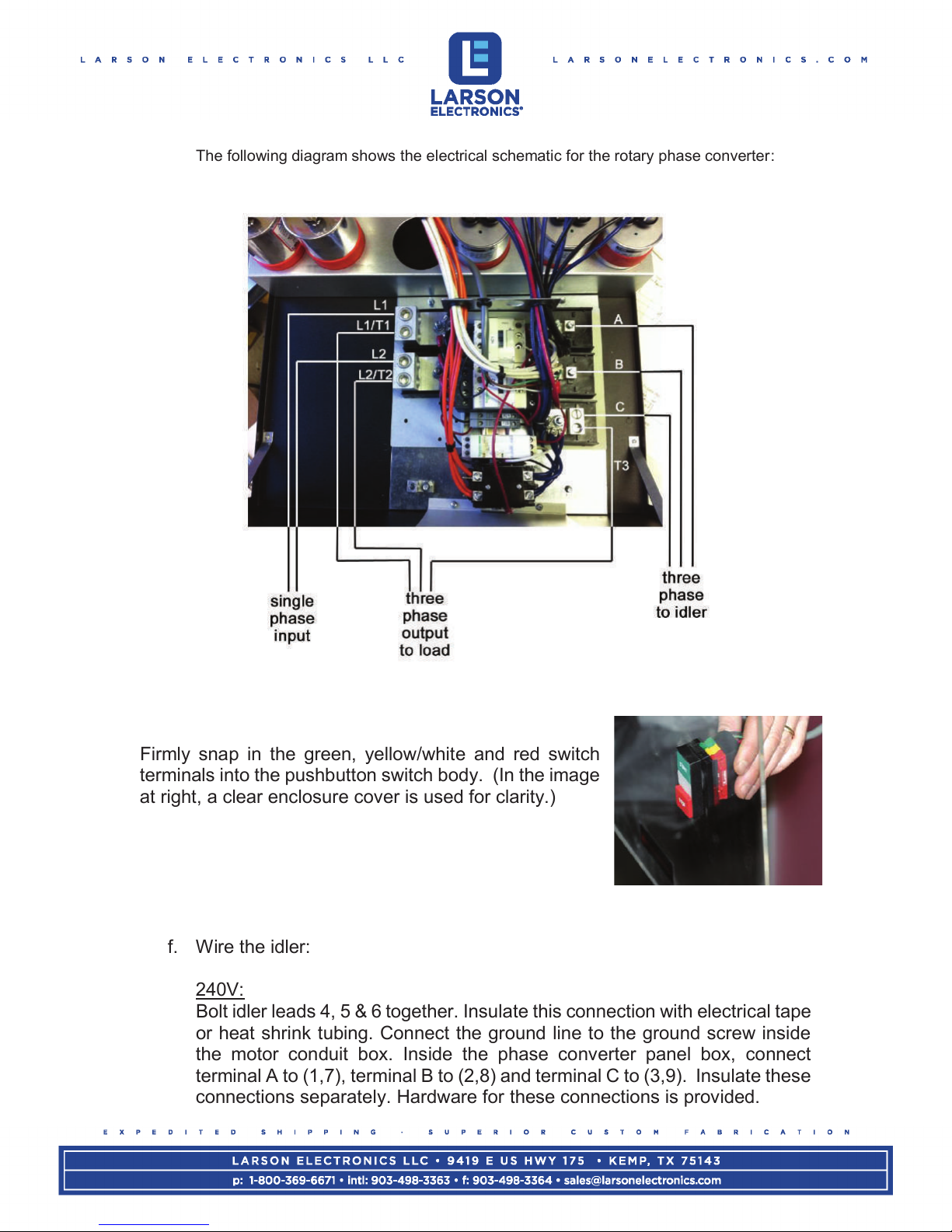
240 Volts Input (1, 7, A), (2, 8, B), (3, 9, C), (4, 5, 6 bolted together and insulated).
480 Volts Input (1, A), (2, B), (3, C). The following bolted together and insulated: (4, 7), (5, 8), (6, 9)
Do not use wire nuts or ground any of these connections. Use the supplied bolts and make all
connections insulated.
* Make sure the Phase Converter Panel, the Idler Motor, and your equipment is grounded!
5. This phase converter does NOT disconnect the single phase power as it passes through the unit, so the
single phase legs remain energized even when the rotary phase converter is off. In addition to installing a
single phase breaker in front of the phase converter, you need to be aware that the single phase power
DOES flow through the phase converter whether the unit is on or off.
6. Before connecting load, verify proper function of phase converter. This will ensure the protection of the
phase converter and your equipment.
For a stock three-phase motor that uses our Stock Motor Panel, wire
the motor according to the diagram for that motor, NOT according to our wiring diagram.
DANGER: HIGH VOLTAGE
Electric shock could result in death or injury. Please
consult qualified personnel for installation.
DANGER: Risk of Electric Shock
Please wait 30 minutes before servicing
This manual is to serve the purpose of providing recommendations for proper performance,
but is not to supersede or replace local or national electric codes. Installation should be done
by a licensed electrician who is familiar with phase converter installations.

1. INTRODUCTION
Larson Electronics specializes in converting Single Phase electrical power to Three Phase
electrical power. The diagram below provides a very simple view of the layout.
An additional 3-phase breaker panel may be installed on the line between the converter control
panel and the 3-phase equipment. This is recommended to protect each piece of equipment and
the wire that feeds that equipment.
The two single phase lines pass through the phase converter and are used to manufacture the 3 rd
line that completes the three phases. The output voltage will always be close to the input voltage.
If a completely different voltage is needed then a transformer installed in front of the phase
converter will be necessary.
The three-phase output is delta configured. This means that voltage measurements between
phases will be similar to input voltages. Voltages should only be measured line to line. Do not
measure voltages line to ground.Most machinery requires a delta three phase voltage and this
third line voltage to ground should not affect operation. If a piece of equipment requires wye voltage
and a neutral connection, the output of the phase converter must be run through a delta-wye
transformer to create the neutral. The phase converter must be started before the transformer is
connected electrically. This is done with a safety disconnect switch. Larson Electronics can
provide these transformers and disconnect switches.

2.0 INSTALLATION
*Note: Each phase converter comes standard with spare fuses for the ones already installed in the
unit.
2.1 PHYSICAL INSTALLATION
All Larson Electronics rotary phase converter units come standard in NEMA 1 indoor rated
enclosures. NEMA Type 3R rainproof enclosures are available with the AI series converters.
2.1.1 PHYSICAL INSTALLATION ENVIRONMENTAL CONSIDERATIONS
The unit should be installed in a location free from the following:
Dirt
Corrosive gases or liquids
Excessive vibration
Airborne particles (particularly metal particles)
Ambient temperatures exceeding 50 degrees C
High humidity
2.1.2 INSTALLATION GUIDELINES (CONTROL PANEL & IDLER)
Steps to install the control panel and idler:
a. Mount enclosure on a secure wall or on the idler (idler mount
models only.) Attach conduit fittings for single phase input line, 3-
phase line to idler and 3-phase line to load.
b. Pull electrical lines into the enclosure. Be sure to pull enough wire
for your load to reach the two terminals on the left side (L1 & L2)
plus the terminal on the right side (T3) of the phase converter
controls. Run the ground lines with each circuit.
c. Connect the lines to the idler/generator to the terminals marked A,
B and C.
d. Connect the three phase output lines to the terminals marked
L1/T1, L2/T2, and T3.
e. Connect the single phase input lines to the terminals marked L1
and L2.

The following diagram shows the electrical schematic for the rotary phase converter:
Firmly snap in the green, yellow/white and red switch
terminals into the pushbutton switch body. (In the image
at right, a clear enclosure cover is used for clarity.)
f. Wire the idler:
240V:
Bolt idler leads 4, 5 & 6 together. Insulate this connection with electrical tape
or heat shrink tubing. Connect the ground line to the ground screw inside
the motor conduit box. Inside the phase converter panel box, connect
terminal A to (1,7), terminal B to (2,8) and terminal C to (3,9). Insulate these
connections separately. Hardware for these connections is provided.

480V:
Bolt idler leads 4 & 7 together, 5 & 8 together, and 6 & 9 together in pairs
inside the motor conduit box. Insulate these connections with electrical tape
or heat shrink tubing. Connect the ground line to the ground screw inside
the motor conduit box. Inside the phase converter panel box, connect
terminal A to 1, terminal B to 2, and terminal C to 3. Wiring diagram is listed
on the idler motor for your reference.
2.1.3 GENERAL WIRING CONSIDERATIONS
-Follow all local, state and national electric codes (NEC) which may supersede
Larson Electronics recommendations.
-T3 is the manufactured line; DO NOT use T3 for any single phase loads.
-Protect all wire and machinery with proper size breakers
-Always make sure rotary phase converter starts before external load(s) are applied.
-A qualified electrician should do all wiring.
-DO NOT assume that a breaker box neutral is a ground! Be sure to ground all equipment
including breaker boxes, phase converter control panel & Idler, disconnect switches,
transformers, loads etc.
-Run all control voltage and equipment controls from lines L1/T1 and L2/T2. Terminals A
and B are for the idler only.
-See Wire Sizing Recommendations (section 2.1.4) for wire sizes. This is VERY
IMPORTANT, as under sizing the wire may lead to a phase converter that does not start
or work properly.
-To minimize voltage drop, Larson Electronics recommends increasing wire size one size for
every 50 feet of run and rounding up.
4 & 7
5 & 8
6 & 9
3
2
1
1 & 7
3 & 9
2 & 8
4, 5, 6

2.1.4 WIRE SIZING RECOMMENDATIONS
FOR 240V:
FOR 480V:
*For all voltages: Conductors listed are minimum recommended based on largest hard starting &
CNC amps. For combined HP’s greater than 50% of maximum total HP listed in the tables above,
consult NEC & local codes for conductor sizing. The above charts do not replace or supersede any
requirements by local, state, or national electric codes.
!

ADDITIONAL NOTES ON WIRING:
It is important to have adequate single-phase electrical service. The actual single phase current
that will flow through the converter is approximately 1.73 times the three-phase current. The
National Electric Code requires 2.5 times the three-phase load current to allow for starting current
and a margin of safety. This is a good conservative calculation to determine your single phase
branch circuit wire size and breaker size.
The power required to run the phase converter is very small and is negligible in figuring out the
power required. The power required is calculated based on the load only.
Wire can never be sized too large, but too small of wire can impede performance and even keep
the converter from starting properly. Increase wire size one size for every 50 feet of run and round
up.
3.0 OPERATION & MAINTENANCE
3.1 STARTING & STOPPING
Larson Electronics phase converters are started by turning the rotary switch to the start position.
The starting sequence is automatic and the switch needs only to be turned to start and released.
The switch should return to the run position on its own. Stopping the phase converter is done in a
similar manner, by turning the switch to the stop position. As with most electrical equipment,
frequent stops and starts are harder on the rotary phase converter than steady operation. The
rotary phase converter is extremely low cost to operate at idle (with no three-phase load), and this
is preferable to a high level of stopping and starting. If your load situation dictates that the rotary
phase converter must be started and stopped frequently, call us about our On Demand with Delay
Off kit for optimum product operation.
3.2 CHECKING VOLTAGES
Measuring Voltage is the easiest way to test to see if the phase converter is working properly.
When voltages are balanced on the three 3-phase lines, currents are balanced. Measuring
current is more difficult as there are different types of current present in the running phase
converter such as regenerative current.
Voltage Measurements:
Measure L1 to L2 This is your single phase voltage as supplied from the utility. To get the
(T1 to T2) most accurate voltage measurements, make sure that the converter is on
and the load is applied.
Measure L1/T1 to T3 This is the voltage between the manufactured line (T3) and one of the
single phase lines. This voltage should be up to 5% higher than the T1 to
T2 single-phase voltage.
Measure L2/T2 to T3 This voltage is the least important. It should also be within 5%. This
voltage will drop when a load is applied.

Do not measure line to ground. Voltages will vary widely when doing this.
When the load is applied, this voltage will drop. Ideally it will only drop to 5% below the
average of the 3-phase voltages.
If your load motor runs backwards, reverse the two single-phase carry through lines T1 and T2 at
the motor that needs reversing. If these lines are switched going to the idler, then the direction of
all equipment will be reversed.
3.3 GENERAL MAINTENANCE
The rotary phase converter may operate continuously with or without a load. The converter will
run cool and quiet in the no load condition because the voltages are well balanced.
1. Never start the converter with a load applied (including transformers)
2. The converter should start within a second or two. Wait to start loads (including
transformers) until the converter reaches full speed. A timer circuit can be used to
automatically start loads after the converter reaches full speed.
3.3.1 MAINTENANCE
Keep dust and moisture from the control panel and the idler. Keep dust from accumulating in the
motor. Dust can be blown out using compressed air. Keep dust from accumulating on the
surface of a TEFC model as this prohibits proper cooling.
3.3.2 LUBRICATION
Larson Electronics rotary phase converter idler/generators are custom made and come with pre-
packed bearings using the lubricant specifically designed for this idler.
DO NOT use Lithium based lubricants. These may cause premature bearing failure and will
void any warranty.
Be careful not to force so much grease into the bearings that the excess finds its way into the
windings of the idler. Some idlers have sealed bearings and will never require greasing. If the
idler has grease fittings located on the end bells of the idler, use the chart below for a greasing
schedule.
Frame
HP Range
Hours running
Grease Type
Up to 210
3-5
12,000
Polyrex EM
210-280
7.5-20
9,500
Polyrex EM
280-360
25-50
7,400
Polyrex EM
>360
60 & 75
3,500
Polyrex EM
This manual suits for next models
1
Table of contents
Other Larson Electronics Media Converter manuals