Larson Electronics NVR-POE-4CH User manual

1
Item Description
VIDEO OUT (VGA, HDMI)
Audio IN / OUT RCA connectors for audio line input and line output
Alarm IN / OUT Terminations are provided for 4 alarm inputs (N.O. or N.C.) and 1 alarm output. See below. (If applicable)
Power connector
NVR-POE-4CH: Connect the 48 Vdc power adapter provided with the recorder to this port, and to a standard 100 ~ 240 Vac power
source using the power cord provided.
NVR-POE-8CH: Connect the power cord provided with the recorder to this port and to a standard 100 ~ 240 Vac power source.
ON / OFF Switch
GROUND Terminal for ground. Connect to earth ground before powering on the NVR.
LAN 10/100BASE-T (NVR-POE-4CH) or 10/100/1000BASE-T (NVR-POE-8CH) Ethernet network interface
USB interface Universal Serial Bus (USB) port for additional devices such as USB mouse and USB Hard Disk Drive (HDD). USB 3.0 port in NVR-POE-8CH
only.
Internal Ethernet switch ports 4 (NVR-POE-4CH) or 8 (NVR-POE-8CH) 10/100 Mbps ports for IP cameras. These ports provide Power over Ethernet (PoE).
Alarm IN / OUT Terminals (Ifapplicable)
Item Description
ALARM IN (1 through 4 and
G, G (ground)) Alarm inputs 1 - 4. Alarm input is tied to ground at G or G terminals through the alarm sensor (N.O. or N.C.).
ALARM OUT (1 and G) Alarm outputs 1 with ground termination.
Mouse control
A standard 3-button (left / right / scroll-wheel) USB mouse can also be used with this NVR. To use a USB mouse:
This quick setup guide provides instructions to initially setup and use the NVR-POE network video recorders (NVRs).
Controls and Indicators
Front panel
Status indicators USB port
Item Function / Description
Status Indicators
POWER
HDD HDD indicator blinks red when data is being read from or written to an HDD.
TX/RX Blinks green when the network connection is functioning normally.
USB Interfaces Universal Serial Bus (USB) 2.0 port for additional USB devices such as a mouse or Hard Disk Drive (HDD).
NVR-POE-4CH Backpanel
Audio IN/OUT
Internal Ethernet switch
LAN
Power Adapter
connector
Power switch
Video Out
(VGA, HDMI)
Ground
terminal
USB
ports with PoE (4)
NVR-POE-8CH Backpanel
Internal Ethernet switch
ports with PoE (8)
LAN
Fan
outlet
Video Out
(VGA, HDMI)
Audio
IN/OUT
Alarm
IN/OUT
USB Power cord
connector
Power
switch
Ground
terminal
NVR-POE Series Embedded Network Video Recorders Quick Setup Guide

2
www.larsonelectronics.com
Step 2. HDD Installation
HDD comes preinstalled. Please contact Larson Electronics for replacement information.
Step 3. Install the NVR
For the following steps, refer to the back panel photo above for the location of connectors.
1. Place the NVR in a location that is secure, well ventilated and clean. The NVR should be positioned such that the back panel connectors
are accessible and the ventilation holes on the sides are not blocked.
2. Connect the ground terminal on the back of the NVR to an earth ground. Refer to local codes for proper grounding.
Step 4. Connect alarm devices to the NVR
Wiring alarm inputs to the NVR
You can wire up to 4 alarm inputs to the NVR.
Alarm IN sensor (N.O. or N.C.)
Typical ALARM IN wiring
Wiring alarm outputs to the NVR
The NVR provides 1 alarm output termination that supports a DC load alarm out circuit. These terminations are marked on the back of the
NVR and are labeled OUT 1 G (G = ground termination).
DC load alarm output circuits
DC loads must operate within the limitation of 12V / 1A. To connect to a DC alarm output, use the following diagram:
NVR
DC Load
1. Plug the USB mouse into the either the front panel or back panel USB connector of the NVR.
2. The mouse will be automatically detected. If the mouse is not detected, the mouse may not be compatible with the NVR. Please refer
to the recommended device list from your provider.
Using the mouse
Action Eect
Left click
Single click: Live view: Select channel and show the quick set menu.
Menu: Select and enter.
Double click: Live view: Switch between single-screen and multi-screen.
Click and drag: PTZ control: pan, tilt and zoom.
Tamper-proof, privacy mask and motion detection: Select target area.
Digital zoom-in: Drag and select target area.
Live view: Drag channel / time bar
Right click Live view: Show menu.
Menu: Exit current menu to upper level menu.
Scroll wheel
Scroll up: Live view: Previous screen.
Menu: Previous item.
Scroll down: Live view: Next screen.
Menu: Next item.
Step 1. Getting Started: Unpacking the Equipment
What’s in the box
Your system includes:
• NVR
• 48 Vdc power adapter (NVR-POE-4CH only)
• 6 foot Ethernet cable
• 6 foot HDMI cable
• Power cable, power adapter and cable
• HDD SATA and power interface cables for internal hard disk drive(s)
Remove the equipment from its packaging and place it on a at, clean surface. Inspect each item. If any visible damage is present, contact
your supplier for a replacement. Verify that your order is complete.
What you need
Although each security system installation is dierent, most require the following items not included with your system components:
• VGA or HDMI compatible computer monitor
• IP cameras and cables compatible with the NVR
• Tools to install the cameras and route power and Ethernet cables
• Fasteners to attach the cameras to the mounting surfaces
• A display device to connect to the NVR. The NVR will connect directly to a VGA video monitor or an HDMI monitor (HDMI cable is
provided). The display device is usually needed only for system setup. It can be disconnected when the NVR is networked for access
across a LAN or Internet.
• Uninterruptible power supply (UPS). This device is used to ensure system stability during voltage surges, sags, and outages. If a UPS is
not available, a power strip with strong surge protection is highly recommended.

3
www. .com
By default, the Setup Wizard will open automatically.
Important Notes for using the Wizard:
• Password Strong” administrator user password. Follow the on-screen
NOTE: There is no factory default
password for this device.
• Date and Time
• Storage - HDD
with it in this window. If you installed an HDD or replaced the HDD, that HDD needs to be initialized by the recorder before it can be
used to record data. Select (check the box for) that HDD, then click Init to initialize the disk. NOTE: Init will erase all data from the
disk and can take several minutes to complete. When the initialization is complete, click Next to continue.
• Network Settings: By default, the recorder acquires it’s network settings using DHCP (dynamic network settings). Depending on
un-check the Enable DHCPoption in the network setup menu, and then click Apply.
Step 9. Access the Menu system
functionality of the system. To use most menus, the user must log into the NVR system, either locally or remotely, with administrative
privileges. To open the Menu system from the Live View screen, right click anywhere in the screen, then select Menu.
Step 5. Install a monitor, mouse, power
For the following steps, refer to the back panel photo above for the location of connectors.
1. Install and setup your monitor in accordance with the instructions provided with the monitor. Do not power it on at this time.
2. Cable the HDMI or VGA connector to your monitor’s VGA or HDMI input. The HDMI interface provides the best performance.
3. Plug the mouse into the USB connector on the front or back of the NVR.
4.
your local area network (LAN) into the RJ45 LAN connector on the back of the NVR.
5. Connect the power cord (or power adapter for NVR-POE only) to the power connector on the back panel of the NVR, and then into a
UPS (recommended) or surge protector.
Step 6. Install cameras
Install your security cameras. Always follow the installation instructions provided with the camera. NOTE: If the cameras feature Power over
Ethernet PoE), the cameras that plug into the ports on the back of the NVR can be powered through those ports.
Step 7. Connecting it together – initial system setup
1. Plug the Ethernet drop cables from the cameras into the RJ-45 Ethernet Switch Ports on back of the NVR.
2. Power on your cameras.
3.
4. Power on the monitor.
NOTE display the input connected to your NVR (HDMI or VGA).
Step 8. Use the Wizard for basic c n setup
Power on the NVR. Normally, an splash screen appears within 2 minutes.
Default Password: ChangeMeN w
Password _____________________________________
(Write New Password Here)

4
www.larsonelectronics.com
Model NVR-POE-4CH NVR-POE-8CH
Ethernet
1x 10/100 Mbps RJ-45 self-adaptive
Ethernet interface,
4 independent 10 /100 Mbps PoE
Ethernet interfaces
1x Gigabit RJ-45 self-adaptive
Ethernet interface,
8 independent 10 /100 Mbps PoE
Ethernet interfaces
Power Over Ethernet Max Power: 40 W
Supported Standards: 802.3af, 802.3at
Max Power: 120 W
Supported Standards: 802.3af, 802.3at
USB 2x USB 2.0 1x USB 2.0 (front panel),
1x USB 3.0 (rear panel)
Hard Drive Interface 1x SATA 2x SATA
Hard Drive Capacity 1x HDDs max, up to 6TB capacity 2x HDDs max,
up to 6TB capacity each
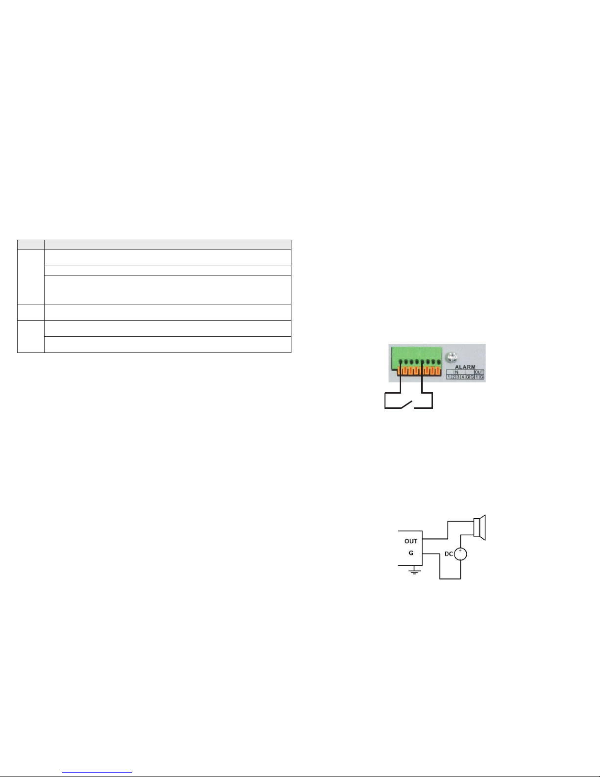
Alarm Input Camera Dependent x4 (NVR) and Camera Dependent
Alarm Output Camera Dependent x1 (NVR) and Camera Dependent
Operating System Embedded Linux
Security Password Protection
Protocols TCP/IP, DHCP, DNS, DDNS, NTP, SADP, SMTP, NFS, iSCSI, UPnP™, HTTPS
Power Requirements 48 Vdc 100~240 Vac ≤ 180 W
Power Consumption ≤ 10 W (without HDD) ≤ 15 W (without HDD)
Weight 2.2 lbs. (without HDD) 6.6 lbs. (without HDD)
Dimensions (in.) 12.4” W × 9.1” D × 1.8” H 15.0” W × 11.4” D × 1.8” H
Operating Temperature 14°F ~ 131°F
Color / Material Black
Material Aluminum
Approvals CE, FCC, RoHS, UL
Remote Client System Requirements
Operating System Microsoft Windows XP, Vista, 7, 8, 10 (32-bit and 64-bit version)
Apple MacOS X 10.5 (Intel x86 only), 10.6 and 10.7
Web Browser Microsoft Internet Explorer 8.0, 9.0, 10, and 11 (32-bit version), Safari 5 and higher
Software Requirements Web Component Installation
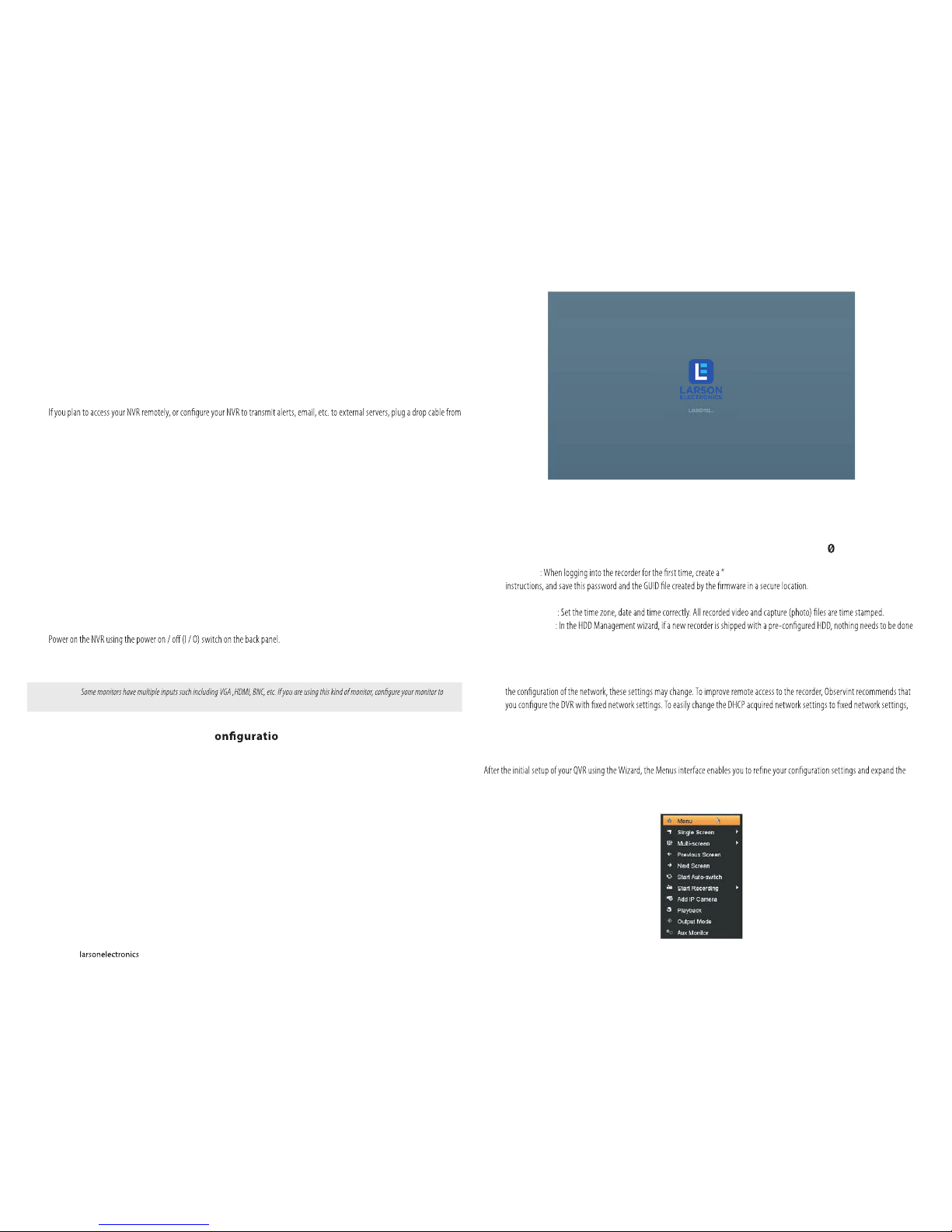
If ID Authentication is not disabled (see the Menu | Conguration | General settings), a login window will open. In the Login window,
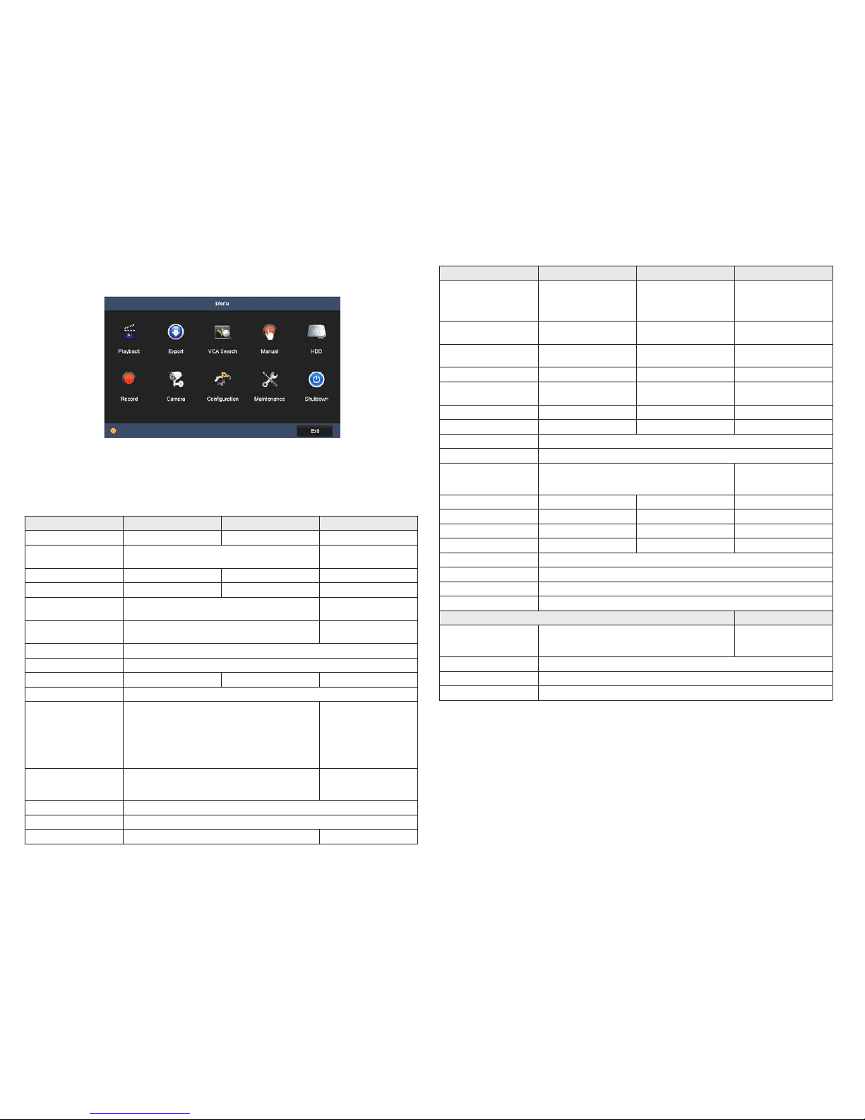
select a User Name with administrative privileges, enter its password, then click OK. A window of Menu icons will open.
For additional information about using your system, refer to the Embedded Network Video Recorder Firmware V3.4.x User
Manual provided electronically with your system.
Specications
Model NVR-POE-4CH NVR-POE-8CH
Number of Channels Supported 4 8
Compression Format Supports H.265/H.264/H.264 OVC
Recording Performance 40 Mbps max 80 Mbps max
Remote Viewing Output Capacity 80 Mbps max 160 Mbps max
Supported Frame Rate per Channel Main stream: Up to 60 fps
Sub-stream: Up to 60 fps
Recording Type Continuous, Schedule, Event, Motion Detection, VCA
Supported IP Camera Resolution 8MP / 6MP / 5MP / 4MP / 3MP / 1080p / UXGA / 720p / VGA / 4CIF / DCIF / 2CIF / CIF / QCIF
Supported Playback Resolution 8MP / 6MP / 5MP / 4MP / 3MP / 1080p / UXGA / 720p / VGA / 4CIF / DCIF / 2CIF / CIF / QCIF
Synchronous Playback 4-ch @ 1080p 2-ch @ 4K, or 8-ch @ 1080p
Video Output VGA, HDMI
HDMI Video Output Formats
4K (3840 × 2160)/30 Hz,
1920 × 1080/60 Hz,
1600 × 1200/60 Hz,
1280 ×1024/60 Hz,
1280 × 720/60 Hz,
1024 × 768/60 Hz
VGA Video Output Formats
1920 × 1080/60 Hz, 1600 × 1200/60 Hz,
1280 × 1024/60 Hz,
1280 × 720/60 Hz, 1024 × 768/60 Hz
Two Way Audio Input 1-ch, RCA (Linear, 1kΩ)
Audio Output 1-ch, RCA (Linear, 1kΩ)
Export Formats MPEG4

5www.larsonelectronics.com
Password Reset
1. If they are not already connected, connect a monitor and a USB mouse to the NVR. Use the USB port at the back on the unit to connect
the mouse. The device will not accept a keyboard; you will use an on-screen keyboard to enter information.
2. Power up the NVR if it is not already running.
3. Right-click anywhere on the screen to bring up an initial menu. Select Menu from this list. You will then get a dialog box asking for a
username and password.
4. Double-click in the lower left corner of this dialog box (not the lower left corner of the screen). There is an invisible button in this dialog
box. Another dialog box will appear, asking for the unit’s serial number and a secure code. A unique serial number will populate on its
own.
5. Call Larson Electronics tech support at 800-369-6671. When a support tech answers, tell them that you have lost the administrative
password to your NVR and wish to reset it to factory default. They will ask for the unit’s serial number, which you got in step 4. Please
provide a return contact number with the serial number. The tech will have to validate the serial number and call back with a
confirmation number. They will provide you with the secure code. Write this code down before entering it into the dialog box on screen
to make sure that you got it correctly from the tech. Click OK when done.
6. After entering the secure code and clicking OK, you will then be able to set the admin password to one of your choosing.
Note: As a security feature, be aware that the secure code that the tech provides will only be good for 24 hours.
Product ID located on bottom of unit.
This manual suits for next models
1
Table of contents
Other Larson Electronics Network Hardware manuals