LaserLine 270UK User manual

GB
®
CAR ALARM SYSTEMS
270UK/278UK INSURANCE APPROVED ALARM
(ORIGINAL REMOTE CONTROL UPGRADE) USER
GUIDE
ISUT270-278UK.p6512/05/2006, 10.241

WARNING
ALARMS MUST NOTBE STEAMCLEANED ORPRESSUREWASHED.
BEFORECARRYING OUTANYELECTRICALWORKONTHEVEHICLEISOLATE
THESYSTEM BYREMOVING SYSTEMFUSE/VEHICLE BATTERY ORDAMAGE
TO THE ALARMMAYRESULT!
270UK/278UK COMPACTALARMSYSTEMFORALLCARS/LIGHT COMMERCIALVEHICLES
This systemismanufactured fromthe highestquality componentstoensure along trou-
blefree operating life and comply with the Britishinsurance industry’s criteria for vehi-
clesecurity for Category 2 à1(L2 à1) (AFTERMARKET SYSTEMS)[Utilising the original
equipment remote testedto Issue 2 Criteria] product, as evaluatedby Thatcham
(MIRRC).
Note: Category2 à1 (L2 à1) product –270/278 alarmsystemis onlyto be fittedinconjunction
with aCategory2(L2) immobiliserto obtainCategory1status forthe vehicle security.
The 270/278 Category2-1alarmisforvehiclesequippedwith a12v negativeearth electrical
system.
Theseinstructionsareintendedto familiarise you with theirvery simpleoperation.
THIS PRODUCTMUSTBEINSTALLED
BYSKILLEDAND QUALIFIED PERSONNEL
ISUT270-278UK.p6512/05/2006, 10.242

pag.3
ENGLISH
1) Index.........................................................................................................................................3
2) Introduction...............................................................................................................................4
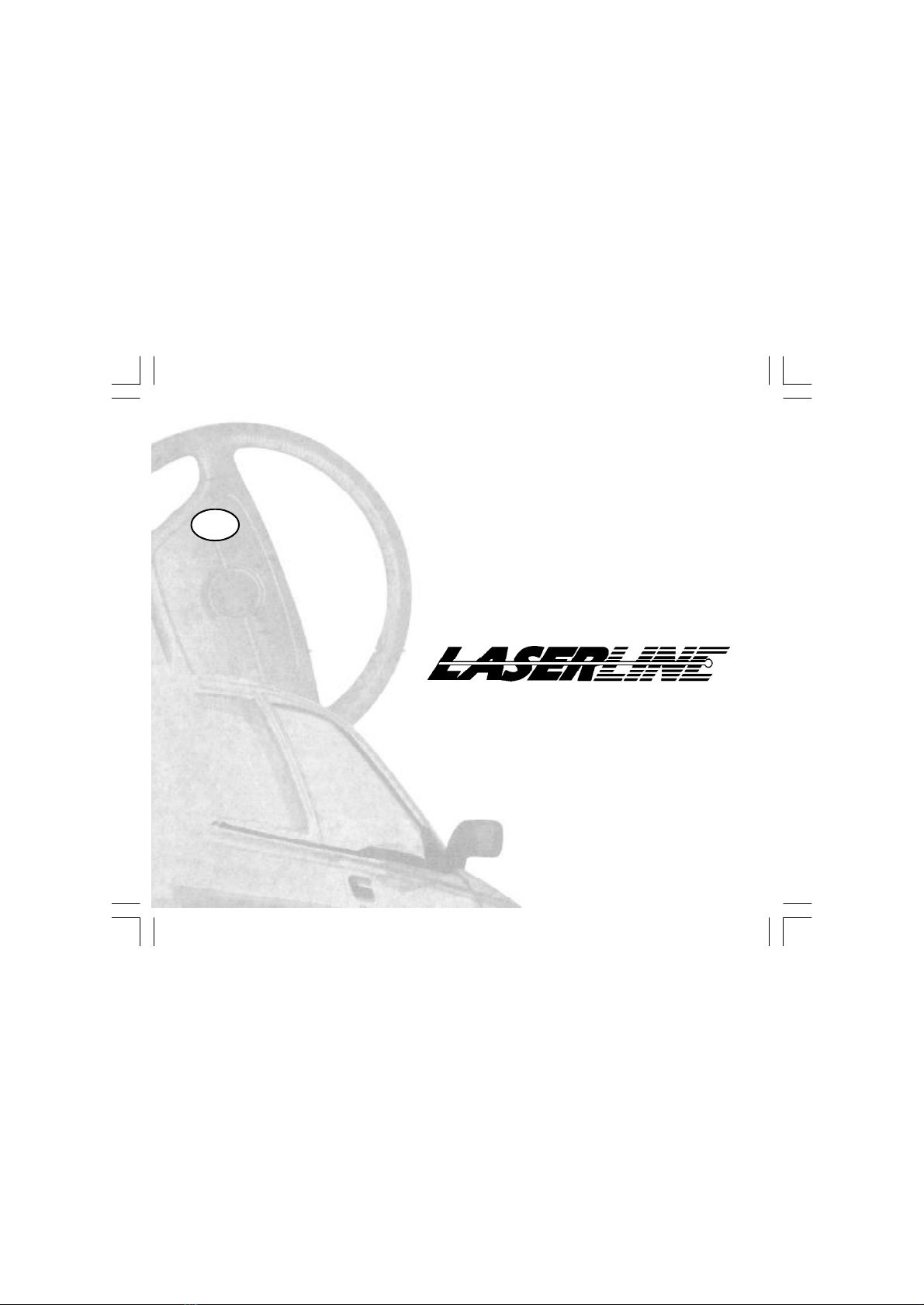
3) 270 System Components.........................................................................................................4
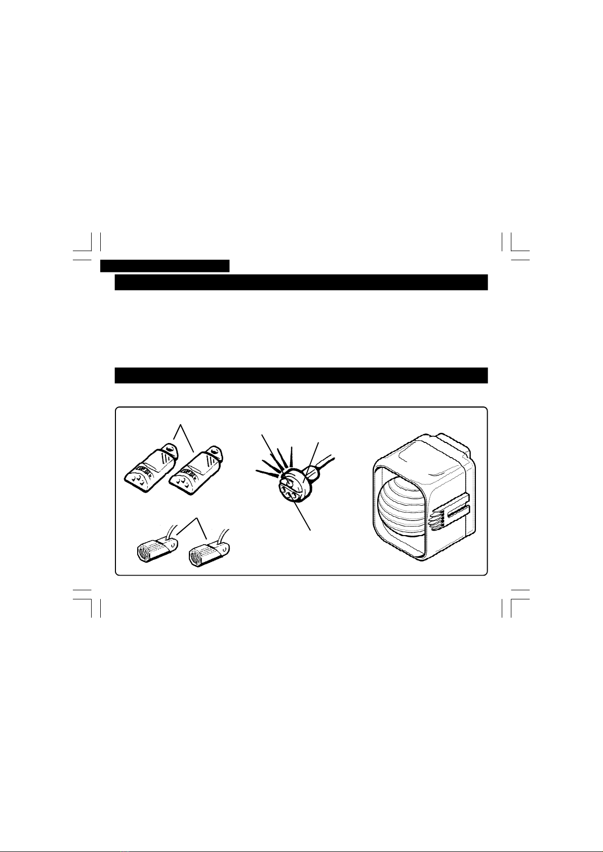
3) 278 System Components.........................................................................................................5
4) Alarmsystem Operation:.........................................................................................................6
4.1 -AlarmSystemArming/Disarming....................................................................................6
4.2 -AlarmCondition...............................................................................................................6
4.3 -AlarmCycle Limitation.....................................................................................................6
4.4 -SensorSelf-Testing............................................................................................................7
4.5 -AlarmTrigger Signalling...................................................................................................8
4.6 -AlarmTrigger History.......................................................................................................8
5) Problem Solving........................................................................................................................9
6) Optional Feature......................................................................................................................9
6.1 -Accidental Disarming.......................................................................................................9
6.2 -Passive Arming..............................................................................................................10
6.3 -Additional Siren..............................................................................................................10
7) FeatureExclusions..................................................................................................................10
8) Garage Function.....................................................................................................................11
9) Disarm UsingYour EmergencyPinCode................................................................................12
9.1-How to Know YourEmergencyPin Code.........................................................................14
10) Self-Learning Of A New Electronic Key.................................................................................16
11) Homologations....................................................................................................................17
12) TechnicalData.....................................................................................................................18
13) LifetimeWarranty..................................................................................................................18
14) Service Inspection.................................................................................................................20
15) CustomerLifetime WarrantyRegistration..............................................................................21
17) TestApprovalNumber..........................................................................................................23
17) EmergencyPinCode.............................................................................................................23
1- INDEX
ISUT270-278UK.p6512/05/2006, 10.243

pag.4
ENGLISH
This alarm system is exclusively adeterrent against possible theft.
Inno waycanitbeconsideredasanactualinsurance against theft.
The manufacturerdeclinesany liabilityforfaults or anomaliesin the alarm system, in itsaccesso-
riesorinthe vehicles’selectric equipment due to incorrect installation orunobservant ofspecified
features/standards.
The manufacturerreservesthe right to makeany changes,whenever theyshouldbenecessary,
without givingprior notice.
2-INTRODUCTION
Receptacle
Red LED
Electronic keys Central unit
Your alarm system consists of the following items:
3-270 SYSTEM COMPONENTS
Ultrasonic detectors
Socket
ISUT270-278UK.p6512/05/2006, 10.244

pag.5
ENGLISH
Electronicsocket
RedLED
Receptacle
Electronickeys
Ultrasonic detectors
Alarm unit
908 Siren
3-278 SYSTEM COMPONENTS
Your alarm system consists of the following items:
Note: The 270 alarm sytem is acompact unit where the alarm and sirenare combind, the 278
alarm system is amodular unit where the alarmand sirenare seperate. The modular system is
normally used when there is limited space inthe engine compart.
KEY*Optional.** Vehicledependent. *** Keyoperateddeadlockingmay disarmthe alarm.
ISUT270-278UK.p6512/05/2006, 10.245

pag.6
ENGLISH
4-ALARM SYSTEM OPERATION
4.1-ALARMSYSTEM ARMING/DISARMIG
To arm the alarm,pressthe lockordeadlock** button on the vehicles originalremote control;direction
indicators lights flashtwice* andthe alarmmaygivetwo acoustictones* to indicate thatthe systemis
now armed.
Once armed,the alarmsystemwilloperate the comfortclosure**/window closure* ifthese functions
havebeen incorporated.
The redLEDinthe receptaclewill remain on for30 seconds(pre-alarm time), then beginto flashto
indicate the alarmsystemisfullyarmed.
To disarm the alarm,pressthe unlockbutton on the vehicleoriginal remote controlorinsertavalid
electronickey into the receptacle socket; direction indicatorslightswillflashonce* and the alarmmay
giveone acoustictone* to indicate that the alarm system isnow disarmed.
Ø at least 3 secondsshould passbetween locking/unlockingthe vehicle, otherwise you may fail
to transmit the new arm/disarm status.
Ø it is possible to use the electronic keyto disarm the alarmbut not to armit.
Ø comfortclosure isafeaturethat may alreadybe incorporatedinto the original remote controlof
the vehicle. Checkvehicleuserguidefor operation.
4.2 -ALARMCONDITION
The systemwillautomatically excludethe sensor,which has generated8 alarm cyclesin one
armed period.Allthe othersensors will continue to protect the vehicle. The maximumnumberof
4.3 -ALARM CYCLE LIMITATION
When fully armedif asensoris activated, the system will generate analarm condition:direction
indicators flashand the siren soundsfor30 seconds(alarm cycle). At the end ofthe alarmcycle, ifthe
samesensor isstill activated,the alarm willgenerate an alarmcycle again.
ISUT270-278UK.p6512/05/2006, 10.246

pag.7
ENGLISH
DOORS/BOOT/BONNET DETECTIONCIRCUITS
1Armthe alarm with the remote control.
2Unlockthe vehicle manually with a key***.
3Within the first30 secondsofarmingthe alarm open andclosealldoors/boot/bonnet. The
alarmwill respondwith 3audible tones,3flashesofthe direction indicatorsandthe LEDwill
goout. If vehicle isfittedwith acourtesy light delay system, you mayhave to waitforthe cour-
tesy light to goout before testing the next doors/boot/bonnet detection circuits.
alarm cyclesforevery sensor is 8, except forpowersupply interruption sensor(10 alarm cycles).
Note: Ifa sensorcontinuesto remain activatedwhilstinthe pre-alarmtime, the system will auto-
maticallyexcludethis sensoratthe endofthe pre-alarmtimeand not generate analarmcondition.
When the alarmsystemisnext disarmedashorter thannormalflashof the direction indicator
lightsandanaccoustictone willbe producedto indicate thatasensor wasactivatedwhilstarming.
To identifythe sensorthatwasactivated, consult the “ ALARMTRIGGER SIGNALLING”
This facilityconfirms the correct operation ofinterior/doors/boot/bonnet detection circuits.This is
indicatedbyaseriesofaudibletones/illumination of the direction indicatorsandaseriesofflash-
ingofthe dashboardLED,when one ofthe circuitsis triggered within the pre-alarmtime. Toself
testthe detection circuits:
4.4 -SENSOR SELF-TESTING
INTERIOR DETECTIONCIRCUIT (Ultrasonic/microwave sensors)
1Sit inside the vehicle.
2Armthe alarm with the remote control.
3Within the first30 secondsofarmingthe alarm, create movement infront ofthe interior sen-
sors (ultrasonics -normally mountedat topofwindscreen). The alarmwillrespondwith 3 audi-
ble tones,1 flash ofthe direction indicatorsandthe LEDwillgo out.
Ø 4secondsmust pass between each detection circuittested before the next self-test signals will
be produced.
Ø turningthe ignition keyon ordisconnecting the power supplyto the alarm system whilst in the
pre alarmtimeor when fullyarmedwill causean immediate alarm condition.
ISUT270-278UK.p6512/05/2006, 10.247

pag.8
ENGLISH
Ifanalarmcondition occurredwhilstyou werenot present, the alarmwill signalitthroughabriefvisual
andacoustic disarm signalinsteadofalongdisarmsignal.
You willbeableto identify the exact alarmcausethanksto the “ ALARMTRIGGER HISTORY”function.
Itispossibleto know the last5alarmtriggerswhich haveoccurredby turningon the ignition key 3
times within 5 seconds while the alarm system is disarmed.
Each alarm causeisassociated to anidentification flashcode:
The alarmcause isdisplayedbythe LEDflashing asmanytimesas the alarmidentification flashcode,
e.g.:
4.5-ALARMTRIGGERSIGNALLING
At firstthe mostrecent alarmidentification flash codewillbe displayed,followed byashortpause
andthen the second-last andso on untilthe fifth one;the displayends automaticallyandan
acoustictone willbe heard.
4.6-ALARM TRIGGERHISTORY
Door-hatch
opening
alarm =
2FLASHES/PAUSE: the ULTRASONICsensorgeneratedan alarmcondition
3FLASHES/PAUSE: the DOOR/HATCHsensorgeneratedan alarmcondition
4FLASHES/PAUSE: the BONNET sensor generatedan alarmcondition
5FLASHES/PAUSE: the IGNITIONKEY sensor generatedan alarmcondition
6FLASHES/PAUSE: the POWERSUPPLY (270 only)sensorgeneratedanalarmcondition
7FLASHES/PAUSE: theBOOT/ADDITIONALsensorgeneratedanalarm condition
FLASH CODES ALARM CAUSE
ISUT270-278UK.p6512/05/2006, 10.248

pag.9
ENGLISH
Note: The trigger history willnot beclearedifthe powerto the alarm system isdisconnected.
Incasethe triggermemorycontains less than 5triggers,the procedurewillautomaticallyendim-
mediatelyafterthe displayof the oldestflashcode.
Onyourreturnto the vehicle, ifyou disarm the systembut donot enter the vehicle(doors/bonnet/
boot) within 40 seconds, the alarm willautomatically re-armitself.Usefulifyou accidentallydis-
armthe alarm fromadistance without knowing.Thisfunction iscancelledifyou enterthe vehicle
(doors/bonnet/boot) within40 seconds from when the alarmis disarmed. Please ensureyou lock
the doorsmanually!
6-OPTIONALFEATURES
Ifyou find you haveto get closerto the vehicle to unlock/disarmthe alarm,thisisnormallyaindi-
cation thatthe originalremote control batteriesmay needreplacing.Referto vehicle’s userguide
forreplacingthe remote batteries.
If youralarmsounds for no apparent reason, pleasereferto the “ALARMTRIGGERHISTORY” for
possiblecondition. Possiblecausesofthe alarmcondition couldbe:
-Vehiclehasbeen tamperedwith.
-Windows/sunroofarenot fullyclosed.
-Doors/boot/bonnet arenot fullyclosed.
-Check thatthe airventshavenot been left open. Air movement withinthe vehiclemaytrigger
youralarm.
-Check the doors/boot/bonnet contact switchesoperate correctly.
-Articles inside the vehicle aremoving e.g. jacket, hangingtoysoraccessories.
6.1-ACCIDENTAL DISARMING*
5-PROBLEMSOLVING
ISUT270-278UK.p6512/05/2006, 10.249

pag. 10
ENGLISH
7-FEATUREEXCLUSIONS
This function allows the alarmto be armedautomatically when you switch offthe ignition and exit
the vehicle, without usingthe originalremote control. 13 secondsafter the lastdoorisclosed/or
13 seconds afterthe courtesy lights goout the alarm willarm.Please ensure you lockthe doors
manually!
To disarm the alarm if itasbeen armed byone ofthe above features:
- original remote control –inthis case you mayneedto promptthe vehiclefor lockingand then
prompt it again forunlocking, in orderforthe alarm to bere-synchronised again with the vehicle
lockstatus;
- emergencyelectronickey –enter the vehicle, the alarm generated byadooropening will be
delayedfor 5seconds,to allow the electronic keyto beinsertedinto the receptaclesocket.
ØWhen armedthrough thesefunctionsthe alarm willnot activate the comfort closing*/window
closing*/additional sensor* andthe ultrasonic/microwavesensor*.
ØAccidental Disarming featuremaynot beavailableon vehicles wherethe originalremote lock-
ingputs on the courtesylightswhen unlocking.
6.2-PASSIVEARMING*
6.3-ADDITIONALSIREN*
This function allows the alarmto beconnectedto an additionalsiren/vehicle horn/pagingsystem
andcanbeprogrammedto obtainacontinuous or intermittent output forthe entire alarmcycle.
Note: Somevehicles mayhaveasimilarlocking feature, whereif the vehicleis unlockedand then
not entered, the vehicle locking systemre-locksthe vehicle. In thiscasethe alarmmayfullyre-arm
activatingcomfort closing*/window closing*/additionalsensor*and the ultrasonic/microwavesen-
sor*.
The followingfeatures maybe disabled:
ISUT270-278UK.p6512/05/2006, 10.2410

pag. 11
ENGLISH
This function allows the alarmsystemto beexcludedtemporarily,inorder to let you leavethe vehicle
inaworkshopfor repairsormaintenance.
When you receivethe vehicleback,you can exitthismodeandrestorethe alarmback to itsnormal
functions.
Toenable garage function:
Œinsert andholdan electronickeyinto the receptaclesocket;
•waituntil the LEDflashes fourtimesinsuccession, accompaniedby fouracoustic tones;
Žcontinue to hold the electronickey in the receptaclesocket forafurther 3 secondsuntilgarage
modeis signalledbya short flash ofthe direction indicatorlights anda short acoustictone;
8-GARAGEFUNCTION
Ultrasonicexclusion (e.g. ifyou want to usethe alarmwhilst keeping vehiclewindowsopen);
Sirenexclusion (e.g. ifyour vehicleis parked inahospitalcar park,ferries,skiing resort etc.);
Acoustictonesexclusion (e.g.no arm/disarmtones, no featurewarningacoustic signals).
Todisableany of the features, insertand keepinsertedanelectronic keyinto the receptaclesocket;
Œto disablethe ultrasonicdetectorsforone arming cycle:removethe electronickey after the LED
hasflashed once,accompaniedbyaacoustictone;
•to disablethe siren forone arming cycle:removethe electronickey after the LED hasflashed
twice in succession, accompanied by two acoustic tones.
Žto toggle OFF the acoustictones:remove the electronickeyafterthe LEDhasflashed three in
succession, accompanied bythree acoustictones.Totoggle ON the acoustictones: remove the
electronickey after the LEDhasflashed three in succession (no acoustictones).
Ultrasonicand Siren exclusion will worknormallyafteryou disarmthe alarm.
Disablingthe ultrasonic detector causesthe optional window closing/optionalsensorto bedisa-
bledand therefore all the associated functions.
Disablingthe siren does not disable the optionalsiren output.
ISUT270-278UK.p6512/05/2006, 10.2411

pag. 12
ENGLISH
Ifyouroriginal remote control/electronic keydoes not workcorrectlyorhas been lost, to disarm
the alarmsystemand enterthe alarminto garagefunction (see section 8) you mustinsert the
“emergency pincode” bydoing the following:
ŒWith the alarmarmed, activate the siren by openingthe dooron the driver’sside;
•Enter the vehicle. The alarm willstop sounding after 30 seconds and then the LEDinstalledon
the dashboard willilluminate for5seconds.Within the 5seconds, turnthe ignition keyON
andOFF for1 second;
ŽThe LED inthe receptaclewillstart to flash andthe alarm is ready to acceptthe PinCode. If
not interrupted,the LEDwillflash10 times. Waitforthe flashescorresponding to each digitof
yourPinCodeto bedisplayed, then turnthe ignition key ONandOFF for 1 second only after
theLEDisoff.ReadPinCode at the endoftheseinstructions fromleft to right. See the follow-
ing example:
•now removethe electronickey.
With garagefunction enabledthe alarm willflash the red LEDin the receptacleevery15 seconds to
indicate garage mode. Ifthe optional immobilisation relayisfittedto the vehiclewith the optional
passivefunctions enabled,thesefunction willbe disabledallowingthe vehicleto bedriven.
To disablethe garage function:
Œturnon the vehicles ignition key andkeep itturnedon;
•insert an electronickeyinto the receptaclesocket;
Žthe exitfromthe garagemodewillbe signalledbya long flashof the direction indicatorlights
anda long acoustic tone;
•remove the electronic key.
9-DISARM USINGYOUREMERGENCY PINCODE
ISUT270-278UK.p6512/05/2006, 10.2412

pag. 13
ENGLISH
5
6
0
5
4
=
=
=
=
=
pause
pause
pause
pause
Pincode entered correctlyalarm
enters garage functionwithout
accoustic tonesorflashing the
directionindicatorlights
Key
On
Key
On
Key
On
Key
On
Key
On
Pincode entered incorrectly
alarmwillstay armed
Key
Key
On
LED Flashes
Acoustic Tones
Ignition Key
On
the pin code to be inserted is 5 6 0 5 4.
ALARM ARMED
ALARMDISARMED
ISUT270-278UK.p6512/05/2006, 10.2413

pag. 14
ENGLISH
Todisplay yourpersonal5-digit emergencypincode with which you canperforman emergency
disarmingofyour alarm system.
Œ Open the dooron the driver’sside;
• Turn the ignition keyOn;
Ž Insert andkeepinsertedan electronic keyinto the receptacle socket;
• Now turnOffthe ignition key;
•Removethe electronic keyfrom the receptacle socket.
The redLED in the receptaclewillflash 10 timesandremain on for10 seconds, the LED willgo out
andthe alarm willstart to flash the LEDaccompanied with acoustictonesanumberoftimesequal
to the numberrelatedto the firstdigitofyour emergencypincode (see the examplebelow).
EXAMPLE: the pincodeto beinserted is56054.
Firstdigit5-Wait5flashes/acoustic tonesforthe firstdigit. Afterthe fifth flash/acoustictone has
been completed andthe LED hasturnedOFF, immediately turnON the ignition key for1 second.
Turnthe ignition OFF andafterapause, the LED/acoustictones will startagain forthe next digitof
the PinCode;Second digit 6 -Wait6flashes/acoustictones forthe second digit. Afterthe sixth
flash/acoustictone hasbeen completed andthe LED hasturnedOFF, immediatelyturnON the ig-
nition keyfor 1second. Turnthe ignition OFF andafterapause, the LED/acoustictones will start
againforthe next digit ofthe PinCode; Thirddigit0-Forthe 0digit, the flashes/acoustictonesto
becompletedare10. Continue untilallthe digits have been displayedandinputtedcorrectly. Ifthe
codeinsertedis correct, the alarmwill automaticallydisarmandentergaragefunction, without a
shortflashof the direction indicator lightsandashort acoustic tone. Ifthe codeisincorrect, the
alarmwill stayarmedandsoundthe siren iftriggeredagain.
Important: to ensurethesecurity procedure,thealarm system does not giveaindication
ofan incorrect codeinputted.
9.1-HOWTO KNOW YOUREMERGENCY PINCODE
ISUT270-278UK.p6512/05/2006, 10.2414

pag. 15
ENGLISH
Itisimperativeto note on apiece ofpaperthispincode, if itis different fromthe original pincode
displayedin the rearofthese instructions.This pincodemust then bestoredin asecure location.
Note:
Ifyou intendto leavetheseinstructions inthe vehicle, the pincode in the backofthese instructions
shouldbe removed for safekeeping.
This pin codeis derivedfromthe firstelectronickey memorisedwhen you self-learnthe electronic
keys.Ifyou want to change the pincodefromthe original code, you mayhaveto follow the self-
learning procedure morethanonce alternatingthe first electronickeyuntilanew pincode isgiven.
thePinCode to noteat the end of these instructionswould be560 54.
Key
LED Flashes Acoustic Tones
5
6
10
5
4
=
=
=
=
=
pause
pause
pause
pause
exit
ISUT270-278UK.p6512/05/2006, 10.2415

pag. 16
ENGLISH
Œ Open the dooron the driver’sside;
• Turn the ignition key ON;
Ž Insert andkeepinsertedan electronic keyinto the receptacle socket;
• Now turnoffthe ignition key;
• Remove the electronic keyfromthe receptacle socket. The redLED in the receptacle will flash
10 times andremain on, indicatingthe self-learning isactivated;
‘ At this point, insert the electronic keysinto the receptaclesocket, thatyou want to storeinto
the alarms memory. The redLEDwill turn off brieflyforeach electronickey thathasbeen
programmedinto the alarmmemory;
’ Tocomplete the self-learning procedure either; turn the ignition ON to exit the function or
wait10 secondsforthe LEDto go out and then start to flash the emergency pin code(see
section “ HowtoKnow YourEmergency PinCode” ).
ØYou should allow no more than 10 seconds between keyinsertions.
ØYou can programa maximumof4 electronic keys.
ØThe electronic keys not programmedduring the last self-learningsession will beautomatically
cancelledbythe alarm memory.
ØIfallelectronickeysarelost, contact your nearest area dealer.
KEY*Optional. ** Vehicledependent. *** Keyoperateddeadlockingmay disarmthe alarm.
10-SELF-LEARNING OF ANEW ELECTRONICKEY
The self-learning function allowsyou to programnew electronickeys orcancel electronickeys.
Tocarryout the self-learningprocedure, anoriginalfunctioning electrickeymustbeavailable.
Then dothe following:
ISUT270-278UK.p6512/05/2006, 10.2416

pag. 17
ENGLISH
This product complies with the requirements of applicable European directives.
You willfindalabelon the alarm unit stating the homologation number, obtained accordingto the
Europeandirective 95/56/CE.
homologation mark
product
11 -HOMOLOGATIONS
manufacturer e12
XXXXXXXX XXV
XX-XXXXXX
XXX XX xxxx
XXX XXXXX
270/278
POWER SUPPLY............................................................................................9-15V negative ground
CURRENT ABSORBEDWITHALARMARMED(with ultrasonic)................................................<13 mA
CURRENT ABSORBEDWITHALARMDISARMED(with ultrasonic).............................................<5mA
PRE-ALARM TIME...................................................................................................................30 sec.
DELAY ENTRY TIME(armedby passive features)......................................................................5 sec.
ALARMCYCLEPERIOD...........................................................................................................30 sec.
ADDITIONALSIRENNEGATIVE CONTROL............................................................................Max 1 A
OPERATING TEMPERATURE.........................................................................................-40°Cto 85°C
DIRECTION INDICATORLIGHTRELAYCONTACT CAPACITY......................................................5+5 A
12-TECHNICAL DATA
908SIREN
POWER SUPPLY............................................................................................9-15V negative ground
CURRENT ABSORBED WHEN CHARGING..............................................................................<25 mA
CURRENTABSORBED WHENFULLY CHARGED....................................................................<2.5 mA
ISUT270-278UK.p6512/05/2006, 10.2417

pag. 18
ENGLISH
Product warrantycoversunits to befree fromdefectsinmanufacturefor the lifetime ownership of
the originalvehicle, in accordance with the terms and conditionsofthiswarrantydocument.
Anyproduct, which isdeemedto bedefective, will bereplacedorrepaired.Accessoriesincluding
electronickeysandadditionalmodules are guaranteedfor aperiod of 12 monthsfrom date of
installation.
1.Product must be installedbyan authorised qualified installer.
2.Ifproduct is transferredby anauthorisedinstalleronto another vehiclethen in thiscase
the warrantyreverts backto 2yearsfromthe date ofthe originalinstallation.
3.Warranty isnot transferable bythe original customerto otherowners ofthe product or
accessory.
4.The customermustcomplete andreturnthe warranty registration document within21
days fromdate of purchaseinorderfor the warrantyto be valid.
5.The warrantycovers product onlyandnot the qualityofthe installation. The warrantyfor
installation isprovidedbythe installer. Wecannot beheld responsiblefor costs arising
due to incorrect installation.
6.Allwarrantyclaims mustbedirected throughthe originalinstaller, accompaniedbythe
originalinvoice, detailingdate of installation andannual service record.Failureto dothis
will render the warrantyinvalid.
7.Continuance of product warrantyis subject to anannualproduct service inspection for
which asmall charge maybeleviedbyanyauthorisedinstaller.Evidence of service
inspection recordmustbeprovidedin supportof warranty claims.
8.Warranty doesnot cover costs incurred forbreakdown assistance orvehiclerecovery, due
to product oraccessoryfailure. Warrantydoesnot extendto reimbursement fordamage
due to defects in productsoraccessories.
TERMSAND CONDITIONS
13 -LIFETIME WARRANTY
ISUT270-278UK.p6512/05/2006, 10.2418

pag. 19
ENGLISH
Warranty will not bevaliddue to the following:
1.Poorresponseto transmittersdue to abnormallyhighelectromagneticinterference.
2.Low batteryvoltageintransmitters.
3.Abuseor mistreatment ofanyproduct or accessory.
4.Loss ordamagedue to accident, fire, lightening, explosion, flood or water, war orcivil
disturbances.
5.Damage causedby externalelectricalsource orfrom abnormalvariation or failureof
power supply.
6.Failurecaused byinstallation of accessories not approvedbythe product manufacturer.
7.Failureofproduct occurringoutsideGreatBritain.
8.Replacement of defective partswithinthe guarantee perioddoes not includeconsumable
parts or includelabour.
9.Ifproduct is repairedby anon authorisedinstallerthe product willceaseto becoveredby
the warranty.
10.Originalmanufacturernegligence.
EXCLUSIONS FROMWARRANTY
CONSUMERSUMMARY
Allwarranties arelimitedto the duration ofthiswarranty.
This is the complete warranty andno otherexpress or impliedwarrantyis valid.Nothing inthis
warranty shallaffect yourstatutoryrights.
NOTE
Manufacturerdeclinesanyresponsibilityfor damageof the alarm/immobiliserandthe vehicle
electrical systemdue to WRONGINSTALLATIONORTAMPERING.
LASERLINESpARESERVES THERIGHTTOEFFECTCHANGESOFTHEPRODUCTWITHOUT
FURTHERNOTICE.
ISUT270-278UK.p6512/05/2006, 10.2419

pag. 20
ENGLISH
14-SERVICE INSPECTION
1YRS 2YRS3YRS 4YRS
PLEASENOTE7 YRS6 YRS5 YRS
Installer’s Stamp
Cert. No.
Reg. No.
Date.
Signature
The above Service
Inspection must be
carried out in order
to ensure the
validity of the
Customer Lifetime
Warranty
Installer’s Stamp
Cert. No.
Reg. No.
Date.
Signature
Installer’s Stamp
Cert. No.
Reg. No.
Date.
Signature
Installer’s Stamp
Cert. No.
Reg. No.
Date.
Signature
Installer’s Stamp
Cert. No.
Reg. No.
Date.
Signature
Installer’s Stamp
Cert. No.
Reg. No.
Date.
Signature
Installer’s Stamp
Cert. No.
Reg. No.
Date.
Signature
ISUT270-278UK.p6512/05/2006, 10.2420
This manual suits for next models
1
Table of contents
Other LaserLine Car Alarm manuals

LaserLine
LaserLine 989E Install guide

LaserLine
LaserLine 290i2 User manual

LaserLine
LaserLine 996 kit User manual

LaserLine
LaserLine 261K User manual

LaserLine
LaserLine 996 User manual

LaserLine
LaserLine 361 User manual

LaserLine
LaserLine 211UK User manual

LaserLine
LaserLine 862 User manual

LaserLine
LaserLine 670T User manual