Lasermet AA-05-PIR User manual

01572-53-000 Page 1 of 17 Issue 1 22nd May 2014
LASERMET
AA-05-PIR
Audio Alert
PIR Triggered
Recorded Message Playback Device

AA-05-PIR Audio Alert Instruction Manual
01572-53-000 Page 2 of 17 Issue 1 22nd May 2014
AA-05-PIR
Audio Alert
Instruction Manual
Contents
Introduction ...................................................................................................................4
Recording a Message ...................................................................................................5
Wiring............................................................................................................................9
Adjusting Volume ........................................................................................................10
Installation...................................................................................................................11
Using the AA-05-PIR...................................................................................................16
Specifications..............................................................................................................17
Contact Details............................................................................................................17

AA-05-PIR Audio Alert Instruction Manual
01572-53-000 Page 3 of 17 Issue 1 22nd May 2014
CE Declaration of Conformity
Manufacturer: Lasermet Ltd.
Lasermet House, 137 Hankinson Road,
Bournemouth BH9 1HR U.K.
Equipment: AA-05-PIR Audio Alert
01303-00-000 Standard
Applicable Directives: Low Voltage Directive 73/23/EEC
CE Directive 93/68/EEC
EMC Directive 2004/108/EC
European Standards to which conformity is declared:
EN 60598-1: 2008
EN 62471:2008
EN 55015:2006
EN 61547:1995 inc. A1:2000
EN 61547:2009
I hereby declare that the above listed products conform to the relevant sections of
73/23/EEC, 93/68/EEC and 2004/108/EC.
Signed:
Name: A. Tyerman
Position: Quality Assurance Manager
Date: 22th May 2014

AA-05-PIR Audio Alert Instruction Manual
01572-53-000 Page 4 of 17 Issue 1 22nd May 2014
Introduction
The AA-05-PIR Audio Alert device is intended to be used in conjunction with
Lasermet’s Laser Interlock systems for the purpose of audibly warning personnel of
hazards by playing back a message recorded on the device. However, the devices
can be readily used independently from Lasermet Interlock systems.
The AA-05-PIR plays back a recorded message up to 40 seconds long (13 seconds
default) when it detects motion (e.g. a person walking past) with its integrated PIR
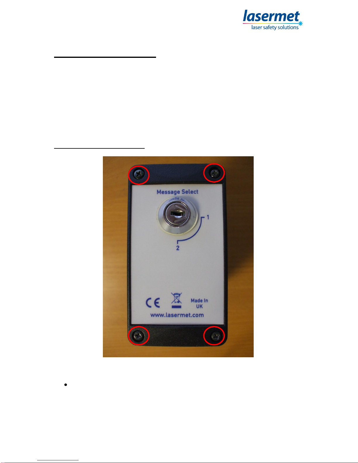
sensor. The AA-05-PIR can hold up to two different messages, which are selectable
using a keyswitch on the side of the unit.
The integrated PIR sensor has detection range of 5m from the device and a
detection angle of approximately 45 degrees around the central point of the detector.
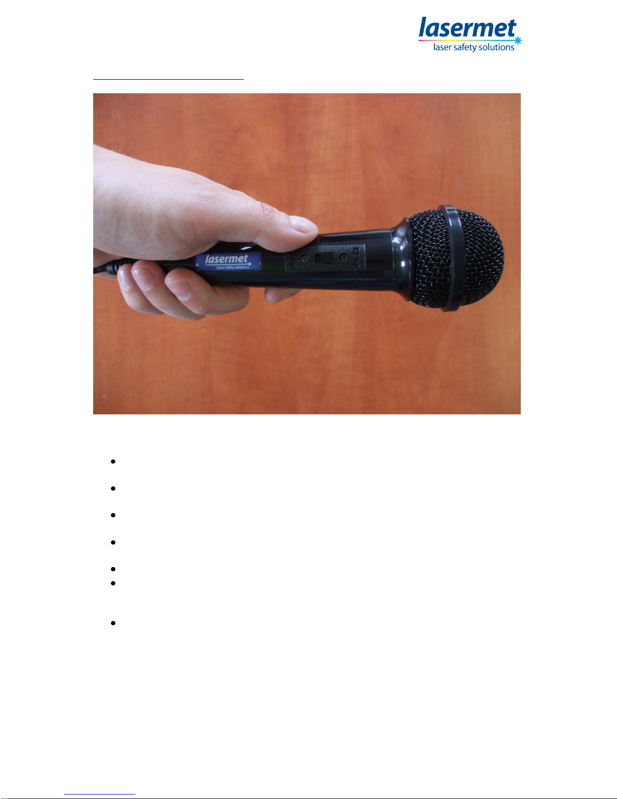
The messages are generally recorded at factory and can be any audio whether it be
speech, music or other. The repetition rate and the number of repetitions of the
message are factory settable to end-user requirements.
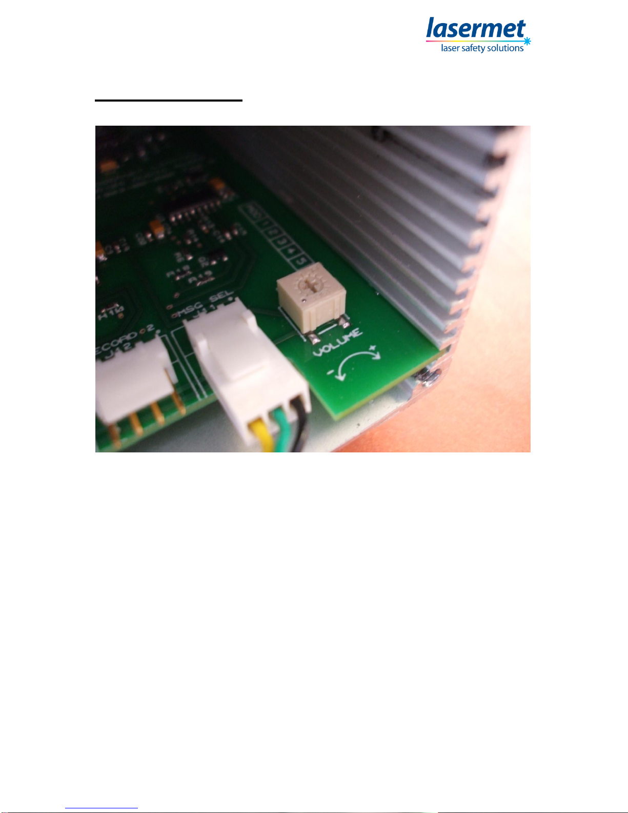
The AA-05-PIR incorporates adjustable volume control and line-out features to allow
audio output to external devices such as amplifiers, speakers and PA systems.
Lasermet provides a full range of laser interlock equipment including control
systems, interlock switches, illuminated warning signs, laser shutters, door locks,
external power supplies etc. which can be connected to provide a complete laser
interlock system. Full support, design and installation is available from Lasermet,
please contact us for any queries. Contact details are given at the end of this
manual.

AA-05-PIR Audio Alert Instruction Manual
01572-53-000 Page 5 of 17 Issue 1 22nd May 2014
Recording a Message
Generally, the customer can provide Lasermet with digital audio files when ordering
an AA-05-PIR and Lasermet will upload the files onto the device for the customer
prior to delivery. Lasermet also has an in-house vocalist who can record written
messages onto the AA-05-PIR prior to delivery.
If the customer wishes to record their own messages, then optional Lasermet part
AA-MIC can be purchased. AA-MIC is special microphone with custom connections
specifically for the Audio Alert range. The following steps indicate how recording with
the AA-MIC is performed.
Step 1 –Remove Side of Case
Figure 1: Removing Highlighted Screws
Remove the four screws circled in red, and remove the side of the case
exposing the circuit board and connections inside.

AA-05-PIR Audio Alert Instruction Manual
01572-53-000 Page 6 of 17 Issue 1 22nd May 2014
Step 2 –Connect Power
Figure 2: Connecting Power Cable
Connect the power cable to the power input connector on the outside of the
device (Refer to “Wiring” section if in doubt)

AA-05-PIR Audio Alert Instruction Manual
01572-53-000 Page 7 of 17 Issue 1 22nd May 2014
Step 3 –Connect AA-MIC Microphone
Figure 3: Connecting the AA-MIC
Connect the AA-MIC to connector J3 (Record 1) on the circuit board, making
sure that Pin 1 on the AA-MIC is aligned with pin one on J3.
Ensure power supplied on to the AA-05-PIR, and the power keyswitch is in
the “On” position.

AA-05-PIR Audio Alert Instruction Manual
01572-53-000 Page 8 of 17 Issue 1 22nd May 2014
Step 4 –Record the Message
Figure 4: Recording the Message using AA-MIC
Slide the switch on the AA-MIC to on and record your message, speaking
clearly into the microphone.
Immediately after you finish speaking, slide the switch on the AA-MIC back to
the off position.
Switch off power to the AA-05-PIR, and ensure the message select keyswitch
is in the “1” position.
When power is reapplied to the AA-05-PIR and motion is detected, your
recorded message should be heard.
Repeat this process until you are satisfied with the message.
To record the second message on the AA-05-PIR, attach the AA-MIC to J12
(Record 2) connector on the circuit board, set the message select keyswitch
to the “1” position and repeat the above steps.
When satisfied, remove power and AA-MIC from the AA-04-PIR and screw
the side of the case back on.

AA-05-PIR Audio Alert Instruction Manual
01572-53-000 Page 9 of 17 Issue 1 22nd May 2014
Wiring
Figure 5: Power Cable Connection
The AA-05-PIR is supplied with an open-ended lead which connects to the power
input on the AA-05-PIR. The open ended leads has two cores, the red should be
connected to the positive of the power supply and the blue to the negative.
+6 to +24VDC should be applied in order to power the unit and when motion is
detected the speech routine will start.
If the audio signal is required to be outputted to an external amplifier or other audio
device, the power input connector has an extra contact to facilitate this. If you are
interested in this feature please contact Lasermet, as an additional lead will need to
be purchased.

AA-05-PIR Audio Alert Instruction Manual
01572-53-000 Page 10 of 17 Issue 1 22nd May 2014
Adjusting Volume
Figure 6: Volume Adjuster
In order to adjust the volume of the playback, a small screwdriver should be used to
turn the volume adjuster (pictured above) clockwise to increase volume or counter-
clockwise to decrease the volume.
The side of the case will need to be removed in order to carry this out –instructions
to do this can be found in the “Recording a message section”. The volume adjuster is
placed within the unit to prevent unauthorised changes to the volume of the device.

AA-05-PIR Audio Alert Instruction Manual
01572-53-000 Page 11 of 17 Issue 1 22nd May 2014
Installation
The AA-05-PIR is supplied with a tilting bracket, which is permanently attached to a
wall or other fixed vertical surface. The AA-05-PIR itself then attaches to this bracket
by means of a padlock. This permits simple and easy removal of the device, whilst
still preventing unauthorised removal.
Positioning
The AA-05-PIR should be mounted in a convenient position for use and wiring.
During installation, cable connections will need to be made and allowance should be
made for the installation of electrical conduit or trunking if required to gain access to
the unit’s location.
It is recommended that there must be a flat unobstructed area of wall extending at
least 200mm above and 200mm below the mounting centre to allow fitment and
removal.

AA-05-PIR Audio Alert Instruction Manual
01572-53-000 Page 12 of 17 Issue 1 22nd May 2014
Mounting the Tilting Bracket
Figure 7: Mounting Rear Half of Bracket
Identify the rear half of the bracket, which has no Velcro dots.
Using suitable screws for the wall or vertical surface you are mounting the
bracket to, screw through whichever of the 8 small holes on the rear of the
bracket are most convenient to the installation. Lasermet recommends using
the holes as shown in Figure 7.
The rear half of the bracket should be level, and in a suitable position for
utilising the AA-05-PIR.

AA-05-PIR Audio Alert Instruction Manual
01572-53-000 Page 13 of 17 Issue 1 22nd May 2014
Figure 8: Mounting Front Half of Bracket
Identify the front half of the bracket which has two black Velcro dots.
Using the supplied security bit and screwdriver in the AA-05-PIR wall
mounting kit, mount the front half of the bracket to the rear half of the bracket
using the security screws.
The small holes on the sides of the bracket can be used to locate the front
half of the bracket at an angle. This allows the AA-05-PIR to be pointed at the
location to be monitored by the PIR sensor.

AA-05-PIR Audio Alert Instruction Manual
01572-53-000 Page 14 of 17 Issue 1 22nd May 2014
Mounting the AA-05-PIR
Figure 9: Mounting AA-05-PIR
Pass the lugs on the rear of the AA-05-PIR through the two holes on the front
of the bracket. You will notice that the Velcro dots on the AA-05-PIR meet with
the Velcro dots on the bracket.
Using the supplied padlock in the AA-05-PIR wall mounting kit, pass the
shackle through the two holes in the lugs and secure the padlock underneath
the AA-05-PIR.

AA-05-PIR Audio Alert Instruction Manual
01572-53-000 Page 15 of 17 Issue 1 22nd May 2014
Figure 10: Mounted AA-05-PIR
The AA-05-PIR is now held securely in place.

AA-05-PIR Audio Alert Instruction Manual
01572-53-000 Page 16 of 17 Issue 1 22nd May 2014
Using the AA-05-PIR
Once the AA-05-PIR is mounted on the wall and the power supply cabling is
attached, the power supply can be turned on. It is suitable for the AA-05-PIR power
cable to be attached while the power supply is on.
Once the power keyswitch on the side of the unit is turned to the “On” position, the
AA-05-PIR will monitor its integral PIR sensor for a signal of a person walking past
the device. Once the person is detected, the pre-installed message will play. The
device will then instate a delay set to user requirements at factory before being able
to be triggered again by another person walking past the device.
The message select keyswitch will select between the first and second pre-installed
message, positions “1” and “2” respectively. This can be switched between at any
time, and the device doesn’t need turning off to do this.

AA-05-PIR Audio Alert Instruction Manual
01572-53-000 Page 17 of 17 Issue 1 22nd May 2014
Specifications
Dimensions:
150 mm wide X 108mm high X 65 mm deep.
Weight:
510g.
Operating Voltage:
+6 to +24VDC.
Power Consumption:
0.48W standby, 3.8W activated.
All figures quoted are approximate. Lasermet reserve the right to alter specifications
without prior notice.
Contact Details
For sales and technical support:
Lasermet Ltd.
Lasermet House,
137 Hankinson Road,
Bournemouth
BH9 1HR
United Kingdom.
Tel.: +44 (0) 1202 770740
Fax: +44 (0) 1202 770730
E-mail: sales@lasermet.com
Website: www.lasermet.com
Table of contents
Other Lasermet Security System manuals
Popular Security System manuals by other brands

Earth Networks
Earth Networks Outdoor Alerting System Strobe instruction manual

Pfannenberg
Pfannenberg PA X 1-05 Operating and installation instruction

First Alert
First Alert FA145C user manual

Eaton
Eaton 405-M Instruction leaflet

KERUI
KERUI G19 operation instruction

Honeywell
Honeywell ADEMCO VISTA-10P Installation and setup guide