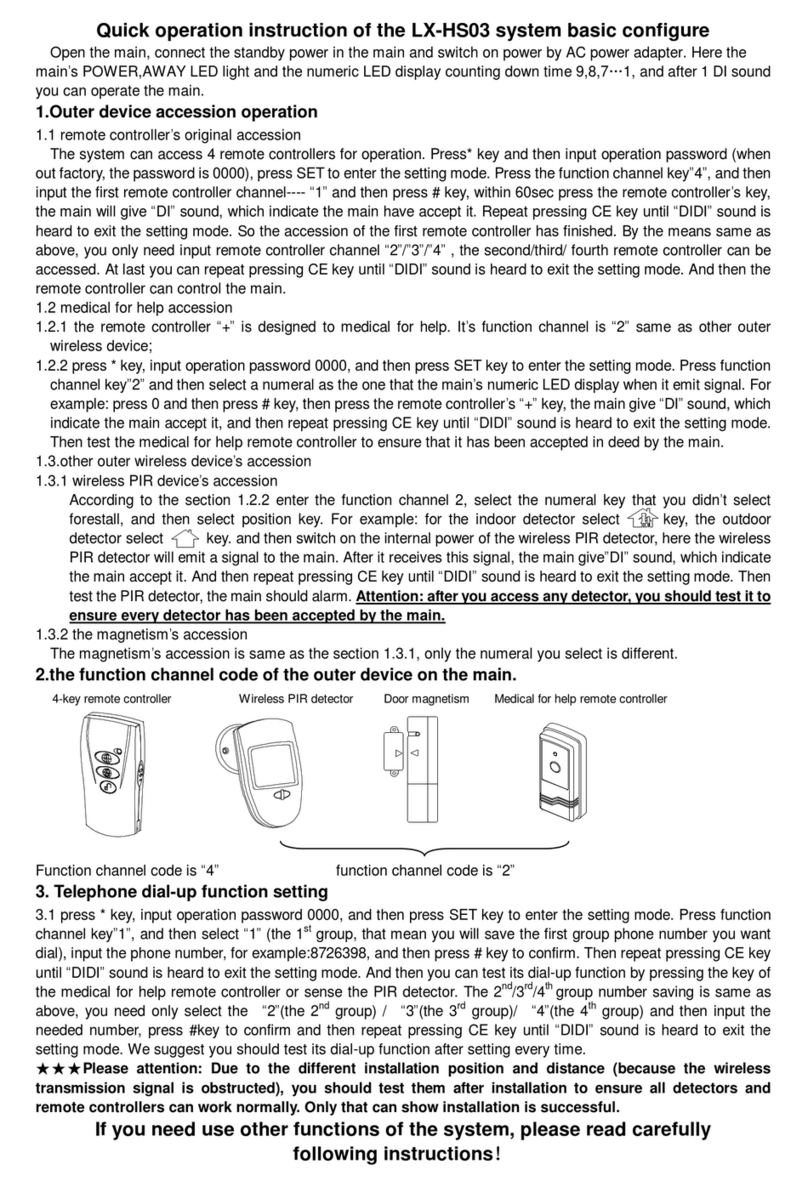
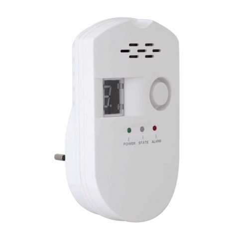
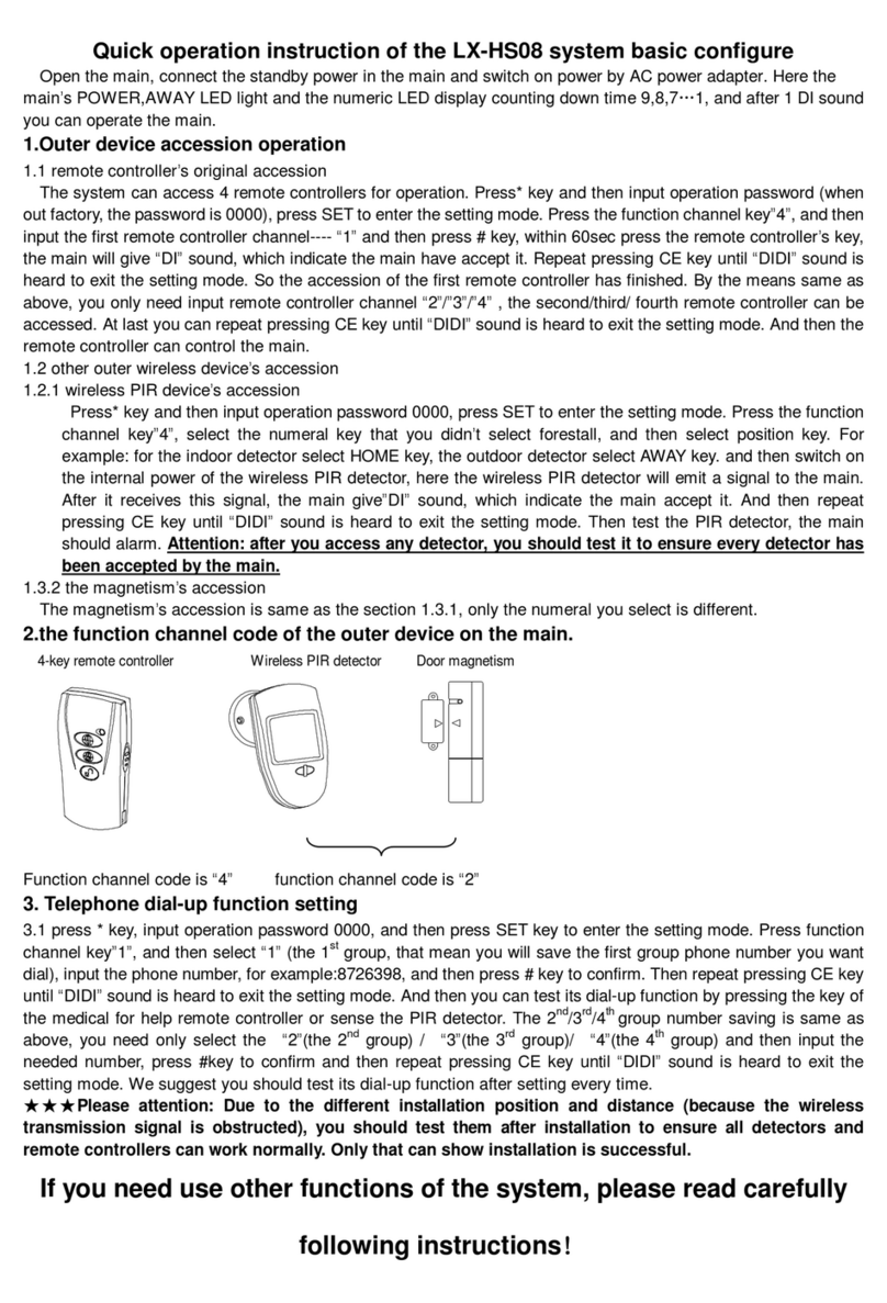
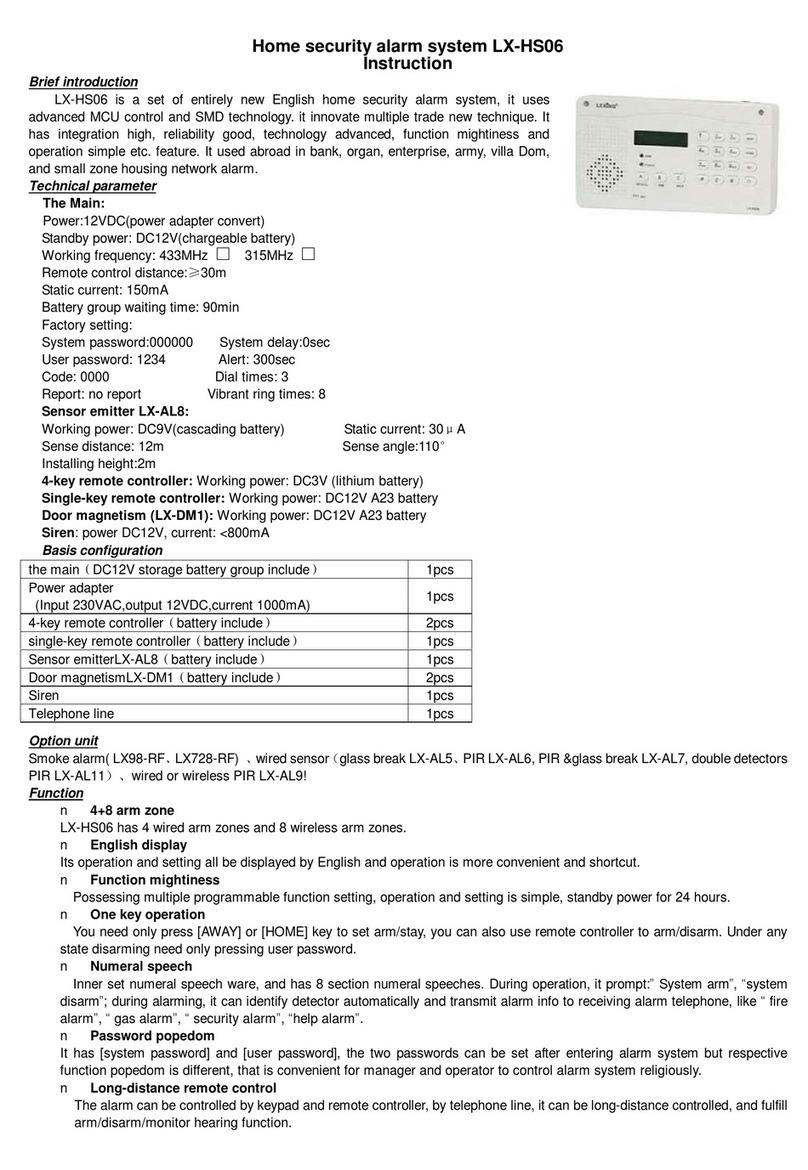
Lexing Panel-F-A16L Product guide

Addressable Fire Alarm Systems /
Fire Alarm Panel-F-A16L
Fire Alarm System
Maintenance Guide & Log Book
CONTENTS
1. FIRE ALARM CONTROL PANEL SAFETY ISSUES………………………..……………… 2
How to use this Fire Alarm Panel safely
2. THE PURPOSE OF A FIRE ALARM SYSTEM……………………………………………… 2
Introduction to fire alarms
3.
USER RESPONSIBILITIES & MAINTAINENCE OF THE FIRE ALARM SYSTEM, INCLUDING THE
FACP & ITS INTEGRAL PSE ………………………………………………………….………… 3
What the end users responsibility is, including daily, weekly, quarterly & annual checks
4. PANEL INDICATIONS & CONTROLS …………………………..……………….………….. 5
A list of indicator LEDs & Control Buttons on the F-A16L Fire Alarm Panel
4.1 GENERAL CONTROLS
4.2 ACCESSED CONTROLS
4.3 SUMMARY OF LED COMBINATIONS AND THEIR MEANING
4.4 CHECKING THE PANELS INDICATION LEDS
4.5 FIRE ALARM SYSTEM AND ITS ACCESSORIES
4.6 LX928-V7 SMOKE DETECTOR USING INSTRUCTION
4.7GLASS BROKEN CALL POINT INSTALLATION INSTRUCTIONS
5. THE FIRE CONDITION ……………………………………………………………………… 14
5.1 HOW THE F-A16L INDICATES AN ALARM
5.2 TO TURN OFF THE ALARM SOUNDERS
5.3 A SECOND ALARM SIGNAL FROM A NEW DETECTION ZONE
5.4 TURNING ON THE ALARM SOUNDERS FROM THE FACP (I.E. EVACUATE).
5.5 RESETTING THE PANEL
6. THE FAULT CONDITIONS …………………………………………………………………….15
6.1 DIFFERENT TYPES OF FAULT
6.2 WHAT TO DO IF A FAULT CONDITION OCCURS
7. DISABLEMENTS …………………………………..…………………………………………… 15
7.1 REASONS FOR DISABLING CERTAIN PARTS OF A FIRE ALARM SYSTEM
8. SYSTEM DESCRIPTION ………………………………………………………….……….…... 15
List of system comments
9. FIRE ALARM LOG BOOK………………………………………………………………………17
A place for you to record details of events such as fires, false alarms, callouts, etc.
10. COMMISSIONING THE SYSTEM, INCLUDING P.S.E…………………………..……….. 20

Addressable Fire Alarm Systems /
Fire Alarm System
Maintenance Guide & Log Book
1. FIRE ALARM CONTROL PANEL SAFETY ISSUES
2. THE PURPOSE OF A FIRE ALARM SYSTEM
Fault Monitoring
There is no need to open this fire alarm during normal operation. Any work carried out on
this system must be performed by a competent person who is familiar with this type of
system. This equipment will operate safely provided it has been installed correctly in
compliance with the Installation Manual. It is recommended that the system is serviced
frequently. It is customary to arrange a regular maintenance contract with a competent
organisation. (Ask the installation company for recommendations). The system needs a
thorough maintenance check annually at the very minimum.
If any part of this Fire Alarm Control Panel becomes damaged, contact the company
responsible for system maintenance to arrange repair / replacement.
A Fire Alarm System is used to provide an early warning of a fire, so that the property can
be evacuated and the fire extinguished if it can be safely tackled, or the local fire brigade
called, according to the company evacuation procedure. Alarms can come from Smoke or
Heat Detectors, or manually be a person operating a Manual Call Point. Split the system into
Zones, each covering a different area of a building. This will indicate which area of the
system is giving the alarm (or fault).During an alarm; the panel will start its sounders, and
indicate which zone has the fire. It will also activate its auxiliary relay.
All circuits must be checked for line integrity. If a part of the system has a problem which
may affect its operation, a fault warning must be given by the fire alarm panel (LED & buzzer
indication). The fault will not be activated.
European Union Directives Conformance
Statement, This product has been manufactured
in conformance with the requirements of all
applicable EU Council Directives.

Addressable Fire Alarm Systems /
Fire Alarm System
Maintenance Guide & Log Book
3.
USER RESPONSIBILITIES & MAINTAINENCE OF THE FIRE ALARM
SYSTEM, INCLUDING THE FACP & ITS INTEGRAL PSE
Disablements
Power Supply Equipment - General Description
An engineer may be required to work on part of a system, while the system is still active
(e.g. extending a detection zone). During such circumstances, it would be advisable to
disable that zone, so that it will not give false alarms. Similarly you may wish to disable a
zone that has a fault that has not been fixed, or a zone covering an area with a temporary
unusual environment, such as an area which is dusty because of construction work etc.
The owner or person having control of the premises should appoint a responsible person
to oversee the effective operation of the Fire Alarm System. Below is a summary of the main
functions the “Responsible Person” is expected to carry out. It is meant to give a brief
outline of user responsibilities for the safe upkeep of the Fire Alarm System.
The F-A16L is composed of two parts, Electricity (AC220V) and lead-acid batteries. Under
normal circumstances the power of the product offered by Electricity (AC220V). When
power is cut, the standby battery (lead-acid batteries) is enabled.meanwhile, the products
will make the corresponding instructions and the buzzer will also sound. At this point you
can press the mute button as long as the product can still work properly. Note: When the
batteries is installed you should switch on Electricity (AC220V) fist, this will prevent a spark
occurring.
N.C NO R++12
COM GND GND
R+
GND
Lead-acid batteries
+
+

Addressable Fire Alarm Systems /
Fire Alarm System
Maintenance Guide & Log Book
The responsible person must:
Daily Inspection
1. Check the system at least once every 24 hours to ensure there are no faults present.
2. Ensure there are arrangements for testing and maintaining the system.
3. Ensure the log book is up to date, and available for inspection.
4. Instruct all relevant occupants on the basic operation of the system, including start
evacuation, silence alarms, silence faults and system reset.
5. Take appropriate action to limit the rate of false alarms.
6. Ensure that all detectors and manual call points remain unobstructed at all times.
7. Liaise with maintenance personnel to ensure that cleaning, maintenance or building work
does not interfere with the functioning and reliability of the fire alarm system.
8. Ensure any changes to the system are recorded with updated drawings, operating
instructions etc.
9. Ensure that there are spare parts (especially Call point elements) held on site. With the
F-A16L Range of Fire Alarm Panels, we recommend the following tests are carried out.
Check that the green Power LED is lit. If there are any yellow fault LED’s lit, or the green
Power LED is not lit, report the fault(s) to the designated site maintenance engineer.
Weekly Test
Quarterly Test (to be carried out by authorised service personnel only
Annual Test (to be carried out by authorised service personnel only
Insert the key, Turn the key to the "CONTROLS ENABLED" then press the “STOP-START”
to detect buzzer, external alarm, relays. Press the button again to Closed. Press the “LED
TEST” testing the LED’S capabilities; Press the “CHECK” testing whether all accessories
are OK.
Check that any servicing or repairs required by all previous logbook entries has been
undertaken.
Visual inspect of the batteries and connections. Check the alarm sounders work on battery
only.
Activate a device from each zone to test the fire alarm (As weekly test).

Addressable Fire Alarm Systems /
Fire Alarm System
Maintenance Guide & Log Book
4. PANEL INDICATIONS & CONTROLS
Every Five Years (to be carried out by authorised service personnel only)
Check every detector, call point, sounder and all auxiliary equipment for correct operation.
Check Transformer output Voltage (32 VAC), Charger Voltage.
Carry out a complete wiring check in accordance with the testing and inspection
requirements of the relevant National wiring regulations. The Batteries should be replaced
because SLA batteries have a working life of 5 years.
Two list of control are available to the User(s) of this Fire Alarm Panel.
SUPPLY FAULT
CHECK
NORMAL
WAITING
ABNORMAL
TROUBLE
ALARM
CHECK
LED TEST
RESET
SILENCE
STOP-START
ALERT MEMORY
CURRENT ALERT
15
14
13
12
11
10
9
8
7
6
5
4
3
1
2
0
ON
ALARM
OFF
POWER

Addressable Fire Alarm Systems /
Fire Alarm System
Maintenance Guide & Log Book
4.1 GENERAL CONTROLS
When the Panel is in its Normal state, the indicator lights on the front of the enclosure give
a comprehensive overview of the System’s current status. Any Fire and Fault conditions are
clearly displayed, and any disablements highlighted. For detailed descriptions of what each
indicator means, please refer to the table on the opposite page.
Use the table below to determine the condition of the panel.
4.2 ACCESSED CONTROL (AVAILABLE TO AUTHORISED USERS ONLY)
4.3 SUMMARY OF LED COMBINATIONS AND THEIR MEANING
To avoid unauthorized changes to critical parts of the Fire Alarm System controls such as
silencing the Sounders, resetting an Alarm condition and implementing Disablements are
only accessible via a secure method of entry which puts the panel into the Accessed state.
To put the Panel into the Accessed State: Turn the key to the “CONTROLS ENABLED”
position (please note the key should not be removed when in this position). To leave the
Accessed state, turn the key back to the OFF position.
Information on how to use the accessed control can be found on Pages 6 to 7 of this User
Manual.
LEDS LIT
POWER CONSTANT GREEN The panel is supplied with power (System Normal)
Checking system
System waiting
SUPPLY FAULT CONSTANT RED
CONSTANT GREEN
A lack of power supply (such as electricity cut, or battery badness)
CHECK
WAITING
System normalCONSTANT GREEN
CONSTANT YELLOW
CONSTANT YELLOW
Some channel detector is abnormal or lost
Some channel detector is fault or shatteris abnormal or lost
NORMALT
ABNORMALT
TROUBLE
CONSTANT
FLASHING WHITE
WITH YELLOW
LED CONDITION PANEL STATUS

Addressable Fire Alarm Systems /
Fire Alarm System
Maintenance Guide & Log Book
4.4 CHECKING THE PANELS INDICATION LEDS
Turn the key switch to “CONTROLS ENABLED” position then press the “LED TEST” button.
All the LED(s) on the left will light and the panel’s internal buzzer will also sound.
ALARM CONSTANT RED Some channel detector is alarm
There is no detector in this channels
This channels of detectors have already alarm, has lost
or damaged
ON CONSTANT GREEN
CONSTANT
FLASHING RED
There is a detector in this channels
OFF
ALARM
System normalCONSTANT GREEN
SHOW FIGURES
SHOW FIGURES
It is display the channels of detector which was unusual /
trouble / alarm
Cycle displays the channels of detector which was unusual /
trouble / alarm
CURRENT ALERT
ABNORMALT
ALERT MEMORY
CONSTANT
YELLOW
OFF CONTROLS ENABLED
Press

Addressable Fire Alarm Systems /
Fire Alarm System
Maintenance Guide & Log Book
4.5 FIRE ALARM SYSTEM AND ITS ACCESSORIES
Connect “COM” with “GND”
Connect “+12” with “+”
Connect “NO” with “-”
Connect “R+” with “+”
Connect “GND” with “-”
The connection-wire of smoking alarm
The connection-wire of alarm
N.C NO R++12
COM GND GND
R+
GND
Lead-acid batteries
+
+
+
+
To strengthen security, besides the standard configure we provide, you can add other
fittings. Our fittings for your choice have: Wireless smoke alarm (LX928-V7)
/siren(LX-SR)/glass broken call.
Maximum number of connectable products: 64

Addressable Fire Alarm Systems /
Fire Alarm System
Maintenance Guide & Log Book
4.6 LX928-V7 SMOKE DETECTOR USING INSTRUCTION
The product is a new type of photoelectric smoke detector, it use
matched with F-A16L.When it detects smoke, its LEDs flash
quickly and the main F-A16L alarm, dial, which tell you in advance
that fire will occurs and avoid unwanted loss, and take you safety
and convenience.
Power supply: DC18V~ DC35V
Static current: 3mA
Working current: 5mA
Double LED: flash once every 10sec(when no alarming)
quickly flash(when alarming).
Connect-wire method: two-wire connection
1. At first, you need install one item in every bedroom and route way at least.
2. Stairway is important for you to rush out when fires occur, so there must install smoke
detector on the top of stairway.
3. You at least require one detector in every space of every floor, including finished attics
and basements.
4. Install one detector beside every electric facility.
5. You’d better Install smoke detectors in the middle of ceiling, because smoke always
spread up;
6. If some reasons cause you can’t install them in the middle of ceiling, you also need to
install them at least 10cm away from the wall.
7. If you like to install them on the wall, they should be installed 10-30.5cm away under the
ceiling. Diagram 1.
8. You need install more than one detector when the length of your hall exceeds 9m.
9. In an oblique roof room, install the detector 0.9m away from the top. Diagram 2.
10. How to install smoke detectors in a removable house. The removable house is short of
heat isolation, so you’d better install the alarm 10-30.5cm away from the ceiling.
Specification
Where Fit To Install Smoke Detector

Addressable Fire Alarm Systems /
Fire Alarm System
Maintenance Guide & Log Book
Where Not Fit To Install Smoke Detector
BEST HERE
CEILING
10CM(4'')
30.5CM(12'')
SIDE WALL
MAXIMUM
ACCEPTABLE HERE
NEVER HERE
MINIMUM
MINIMUM
10CM(4'')
DIAGRAM 1
IN THIS AREA
0.9M(3ft)0.9M(3ft)
FROM PEAK
HORIZONTAL DISTANCE
ANYWGERE
DIAGRAM 2
1. Where combustion are permitted to produce. For example unventilated kitchens,
garages,and furnace.
2. Near fanner.
3. In very damp, humid or steamy areas: Keep units at least 3m away from showers saunas,
dishwashers, etc.
4. In very dusty, dirty, or greasy areas.
5. In very drafty areas, where smoke will be blown away from the unit completely.
6. In air-logged areas, that will clog the sensing chamber.
7. Where Less than 305mm away from fluorescent lights. Electrical “noise” can interfere
with the sensor.
8. In “dead air” space, for example, in Diagram 1, near the corner less than 10cm.
9. In smoking meeting room, don’t install the alarm there for the unit will alarm when
several persons smoke.
BEDROOM
BASEWENT
KITCHEN BEDROOM
SMOKE ALARM FOR ADDITIONAL PROTECTION
BEDROOM
SMOKE ALARM FOR MINIMUM PROTECTION
LIVING ROOM
BEDROOM
LIVING ROOM
BEDROOM
SINGLE FLOOR PLAN
MULTIPLE FLOOR PLAN
KITCHEN
BEDROOM

Addressable Fire Alarm Systems /
Fire Alarm System
Maintenance Guide & Log Book
Connection-wire Diagram
Installation
Test
Loosen the screws arrow pointing in the right
figure and twine the line head on the screw thread
under gasket. And then tighten up the screws.
•Terminal 5 connect R+ " +" of control unit
•Terminal 2 connect GND "–" of control unit.
1. Press and hold the base and turn it counterclockwise, take down
base.
2. According to the number mark on base and connection-wire
diagram, connect wire to number corresponding screw with gasket.
3. Fix the base on the selected position.
4. Cover the alarm body: make the short line on the base aim at the
long line on alarm body and turn clockwise until the long line on base
aim at the long line on alarm body.
1. Switch on power, the LEDS should flash once at the same time
every about 10sec.
2. Put magnet near inner pole reed tube and attract it(attention the
position like right fig.), the LEDs turn to flash quickly and the main
F-A16L alarm and dial.
3. If the LEDs don’t flash quickly, please check whether the magnet
using is correct or not.
magnetism

Addressable Fire Alarm Systems /
Fire Alarm System
Maintenance Guide & Log Book
Regular Maintenance
Coding Method
1. Test it at least once a week.
2. Clean the smoke alarm at least once a month. Gently vacuum off dust using vacuum’s soft
brush attachment.
3. Never use water, cleansers to clean your smoke alarm since they may damage the unit.
LX928-V7 smoke detector can be identified by channel code; by 6-bit coding switch its
channel code has 64 coding methods (detail in following table).
654321
SABRE ON
1
0
Coding Channel Coding Channel Coding Channel Coding Channel
000000 0 010000 16 100000 32 110000 48
000001 1 010001 17 100001 33 110001 49
000010 2 010010 18 100010 34 110010 50
000011 3 010011 19 100011 35 110011 51
000100 4 010100 20 100100 36 110100 52
000101 5 010101 21 100101 37 110101 53
000110 6 010110 22 100110 38 110110 54
000111 7 010111 23 100111 39 110111 55
001000 8 011000 24 101000 40 111000 56
001001 9 011001 25 101001 41 111001 57
001010 10 011010 26 101010 42 111010 58
001011 11 011011 27 101011 43 111011 59
001100 12 011100 28 101100 44 111100 60
001101 13 011101 29 101101 45 111101 61
001110 14 011110 30 101110 46 111110 62
001111 15 011111 31 101111 47 111111 63

Addressable Fire Alarm Systems /
Fire Alarm System
Maintenance Guide & Log Book
4.7 GLASS BROKEN CALL POINT INSTALLATION INSTRUCTIONS
Function
Electrical Rating
Glass Fitting
Testing
Glass Replacement
Warning
Connection
Notes
Under emergency condition break the glass
and make the main alarm.
AC (50Hz) 8V min. 250V max up to 10A
DC 8V min. 24V max up to 10A
48V max up to 3A
Contact resistance 0.1ohms max.
Feed the glass upward to push the cam down and fit under slider, locate bottom of glass
into recess.
Hold the bottom of glass in position and rotate the thumbwheel to raise the top of the glass.
Fit the call point cover by hooking it into the top of the unit and making sure that the glass.
is properly seated, and then tighten the cover fixing screw.
Push the test key through the hole in the underside of the call point to engage the test cam
mechanism and push to operate the cam mechanism. At this point the test key is retained
in the call point and pulling it out will reset the glass.
Open front cover, remove broken glass and follow procedure outlined under glass fitting.
Do not fit more that one core per terminal screw, always use one screw for ‘IN’ and one
screw for ‘OUT’ to avoid possible bad connections. Maximum size cable 4.0mm².
Terminals 1&3: Normally open contacts.
The unit as supplied is suitable for indoor application.

Addressable Fire Alarm Systems /
Fire Alarm System
Maintenance Guide & Log Book
5. THE FIRE CONDITION
5.1 HOW THE F-A16L INDICATES AN ALARM
5.2 TO TURN OFF THE ALARM SOUNDERS
When the F-A16L Fire Alarm Panel is set into alarm: LED will show that which zone is alarm.
Then the ALARM LED in the alarm panel will light. ALARM LED which corresponds to the
area of fire will glimmer .The internal buzzer will sound, warning sounder and output
equipment assisted will be started.
Turn the key switch to the “CONTROLS ENABLED” position, make controller quiet sound
according to press “SILENCE”, shut off the warning generator of outside according to
press “STOP-START”. But the LED is in charge of still revealing the area that calls the
police, red “ALARM” LED on the panel still keeps on, red “ALARM” LED in the area of alarm
still glimmers continuously, the fire insurance relay assisted will be in the state of
activating.
5.3 A SECOND ALARM SIGNAL FROM A NEW DETECTION ZONE
If another detection Zone is activated then the Alarm Sounders which have been silenced
will activated again. LED “CURRENT ALERT” will show the alarm zone and the LED “ALERT
MEMORY” will shows the area zone this and last time by turns. In addition red “ALARM”
LED of the new warning area glimmers; originally fire zone is keep previous condition.
5.4 TURNING ON THE ALARM SOUNDERS FROM THE FACP
(I.E. TO EVACUATE THE BUILDING)
5.5 RESETTING THE PANEL
With the control key in “CONTROLS ENABLED” position, momentarily pressing the
Start-Stop will cause the Alarm sounders to sound. Pressing the Start-Stop button again
will Silence the Alarm Sounders.
Check the cause of the alarm activation. If the cause of the alarm was by detector activation
(e.g. cooking smoke), the smoke will have to be cleared from the room before the panel can
be reset. Reset the panel by pressing the reset after the sounders and panel buzzer have
been silenced.

Addressable Fire Alarm Systems /
Fire Alarm System
Maintenance Guide & Log Book
6. THE FAULT CONDITION
7. DISABLEMENTS
8. SYSTEM DESCRIPTION
6.1 DIFFERENT TYPES OF FAULT
7.1 REASONS FOR DISABLING CERTAIN PARTS OF A FIRE ALARM SYSTEM
If the call point is still active, or the detector is still smoky, this will cause another alarm
straight after the panel is reset, so will set off alarm bells again.
If a fault occurs, the responsible person should:
Turn key switch to “CONTROLS ENABLED” and press “SILENCE” button to silence the
fault buzzer.
Write down the fault (s) in the Log Book at the back of this Manual. Take appropriate action
to correct the fault (Usually by contacting the service engineer) On the F-A16L panel, the
fault indications (except system fault) are non latching. That is, when the fault has been
cleared, the fault indication will turn off. When all faults have been cleared, the panel will
return to its quiescent (normal) condition. When a fault has been rectified the indicator light
for that Fault is automatically turned off. If all Faults are cleared, the General Fault light will
go out and the Panel’s Internal Sounder will be silent (if not already muted).
Certain parts of this Fire Alarm Panel can be temporarily disabled (i.e. switched off) to suit
prevailing conditions. For example, if there is a risk of a False Alarm in a zone, for example,
from vehicle exhaust smoke in a loading bay, it is possible for the user to disable that zone
during the risk period and then enable it again afterwards. During a disablement of a
zone(s), no fire or fault signal will be processed for that zone(s). Only zone(s) in a non-alarm
state can be disabled, that is zones already in fire cannot be disabled. External sounders
can also be disabled as could be required in certain conditions.

Addressable Fire Alarm Systems /
Fire Alarm System
Maintenance Guide & Log Book
FIRE ALARM SYSTEM SUMMARY:

Addressable Fire Alarm Systems /
Fire Alarm System
Maintenance Guide & Log Book
9. FIRE ALARM LOG BOOK
It is recommended that this LOG BOOK section of the Manual be maintained by the
responsible person(s) on site, who should ensure every event is properly recorded
(including fire alarm conditions, failures, tests, temporary disconnections, disablements,
enablements, dates of installing engineers’ visits together with a note of any outstanding
work or panel conditions). This LOG BOOK must be available for inspection at all times.
You can photocopy this log book to provide extra pages for when this book is full.
Fire alarm events should be subdivided & recorded on separate sheets in the log book. The
event categories are:
Maintenance work
False alarms – Where the sounders have activated with no signs of a fire.
Any other events- This would be genuine alarms or faults.

Addressable Fire Alarm Systems /
Fire Alarm System
Maintenance Guide & Log Book
MAINTENANCE WORK
DATE
TIME
ZONE / LOCATION
REASON FOR WORK
WORK CARRIED OUT
ADDITIONAL WORK
REQUIRED
SIGNED

Addressable Fire Alarm Systems /
Fire Alarm System
Maintenance Guide & Log Book
FALSE ALARMS
DATE
TIME
ZONE /
LOCATION
CAUSE (IF
KNOWN) OR
ACTIVITIES IN
ALARM AREA
MAINTENANCE
VISIT NEEDED
(YES/NO)
MAINTENANCE
FINDINGS
CATEGORY
OF FALSE
ALARM
FURTHER
ACTION
REQUIRED
SIGNED

Addressable Fire Alarm Systems /
Fire Alarm System
Maintenance Guide & Log Book
10. COMMISSIONING THE SYSTEM, INCLUDING P.S.E.
The commissioning of this fire alarm system should be performed by a qualified
commissioning engineer (i.e. Design considerations, Limitations of false alarms,
Installation recommendations).
• The system layout drawing should be checked for accuracy & stored in a safe place,
accessible to any fire officer.
• The system set-up data chart should be checked for accuracy.
• The fire alarm log book contact details should be checked for completeness.
• The insulation of cables should be checked.
• The Earthing should be checked.
• The PSE mains feed from a 3A spur should be checked. It should be protected by an
over current device (MCB)
NOT an earth leakage device (RCD)
• The PSE Charger voltage should be checked & adjusted if necessary (28.3 with batteries
disconnected).
• The battery voltage should be checked (should be between 24 & 27V).
• All call points & detectors can signal an alarm condition and indicate the correct zone (and
text message) on the fire alarm panel.
• The Certificate of Installation & Commissioning should be completed, and the whole user
manual passed to the relevant person on site.
Add:No.35 Zhuquan Road,Science&Technology Area.
Ninghai,Ningbo,Zhejiang,China
Fax:+86-574-65335000 65335333
Tel:+86-574-65335088
E-mail:[email protected]
www.lexing.com.cn
www.lexing.com
NINGBO LEXING INDUCTOR ELECTRONIC CO.,LTD
Table of contents
Other Lexing Security System manuals
Popular Security System manuals by other brands

Response
Response ML6 Installation and operating instructions

Adiant Mobile
Adiant Mobile LifeBeacon quick start guide

Emergency Caller Products
Emergency Caller Products EC-4 Programming Quick Reference Guide

Axis
Axis FA54 user manual

Risco
Risco Agility 3 Installer manual

M-system
M-system 48NDT instruction manual