LaserPoint CSA-20-D12 User manual

LaserPoint srl –20090 Vimodrone - Via Burona, 51–tel. 02 27 40 02 36 - fax. 02 25 02 91 61-e-mail: sale[email protected] www.laserpoint.eu 1
Release: JUNE .06
T
Th
he
er
rm
ma
al
l
O
OE
EM
M
L
La
as
se
er
r
S
Se
en
ns
so
or
rs
s
M
Ma
an
nu
ua
al
l
Instruction Manual
Edition 2 –July 2017

LaserPoint srl –20090 Vimodrone - Via Burona, 51–tel. 02 27 40 02 36 - fax. 02 25 02 91 61-e-mail: sale[email protected] www.laserpoint.eu 2
TABLE OF CONTENTS
TABLE OF CONTENTS......................................................................................................2
1 - GENERAL......................................................................................................................3
2. INSTALLING THE CS OEM SENSOR HEAD SERIES...................................................4
2.1 -General.........................................................................................................................................4
2.2-Output Signal Condictioning......................................................................................................4
2.3 - Installation of Air Convection Cooled Series..........................................................................5
2.4 - Installation of Water Cooled Series .........................................................................................5
3 –STANDARD OEM SENSOR HEADS............................................................................6
Standard Thermal Heads..................................................................................................................6
4 - SAFETY .........................................................................................................................9
5 -WARRANTY....................................................................................................................9
6 –LIMITED LIABILITY ....................................................................................................10

LaserPoint srl –20090 Vimodrone - Via Burona, 51–tel. 02 27 40 02 36 - fax. 02 25 02 91 61-e-mail: sale[email protected] www.laserpoint.eu 3
1 - GENERAL
Laser Point’s OEM Detector Heads CS Series is power and energy measurement device designed
for their integration in laser sources or laser machines for direct monitoring. They can be applied to
all kind of laser sources and machines to allow OEMs with diagnostic tools that coupled with leaky
mirrors or splitters can continuously monitor laser sources and laser systems.
Laser Point’s CS Detector Heads are thermopile detector units based on a sensor integrated in a
suitable mechanical housing, that according to the power sustainable by the sensor are either
convection air cooled (CSA) or water cooled (CSW).
Unpacking and inspection
Each OEM Detector Head has been carefully inspected and tested prior to shipment. Unpack and
assure that no damage occurred during transport and handling. Any damage must be immediately
reported to Laser Point and to the Carrier.
Do not use any device if it looks damaged, or if you suspect that it does not operate properly.
Operating environment
Allow at least 5 minutes of warm up time after the turn-on to achieve maximum stability of the
electronics. Refer to the specs attached to this manual for environmental and operating conditions.

LaserPoint srl –20090 Vimodrone - Via Burona, 51–tel. 02 27 40 02 36 - fax. 02 25 02 91 61-e-mail: sale[email protected] www.laserpoint.eu 4
Front Flange
Sensor Disc
Active Area
Laser Beam
2. INSTALLING THE CS OEM SENSOR HEAD SERIES
Installation must be performed by an operator qualified to
the use of voltage devices. LaserPoint is in no way liable for
any damage resulting from misuse, careless or use above
rated limits for the instrument.
2.1 -General
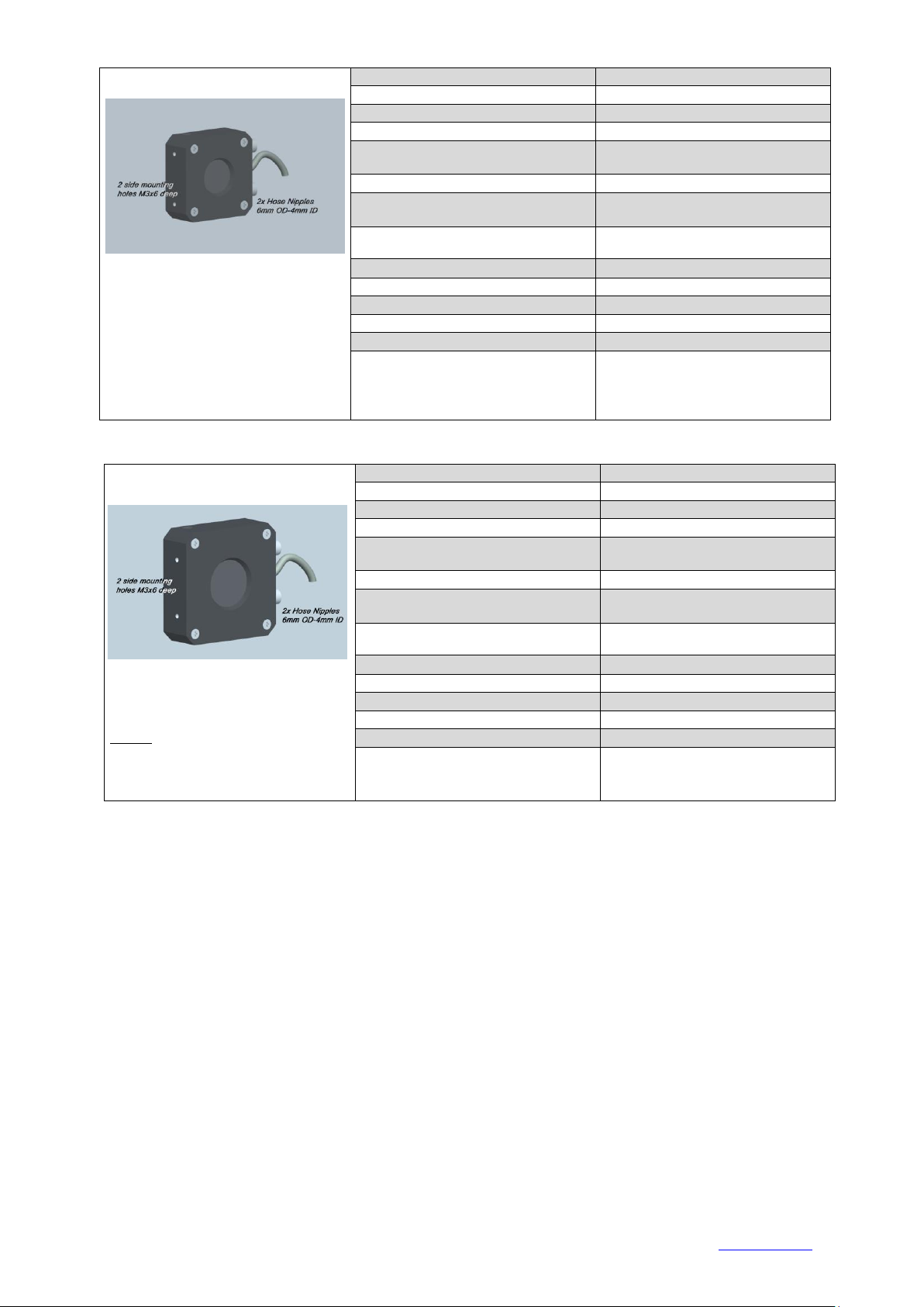
This series includes compact, conduction or water cooled
heads: the setup is made by sensor disk,
housing and a connecting device
(LaserPoint’s Intelligente Identification
System-IIS, BNC connector or Pigtail output).
The head has been previously mounted and tested in
house, so no additional work has to be done except
connecting to a conditioning electronics and
calibrate.
Output Signal Voltages depend on the
applied amount of power/energy and are
expressed as mV per incident W (mV/W). The amount of successive amplification thus depends on
the overall measurement range (Min to Max value). A safe minimum measurable value, to avoid
influence of noise, has to be considered as at least 4 times the value of NEP (Noise Equivalent
Power) . Please refer to the head specs table at the end of this catalog to identify the correct value of
NEP.
As a safety rule, never let the sensor disc area face power/ energy densities (originated by a too
small size beam or hot spots) that exceed the values specified for the absorbing coating . If the
absorber is damaged, measurements may be affected and a substitution of the sensor may be
necessary (refer to Section 4 for individual threshold of each sensor).
2.2-Output Signal Condictioning
External connection options include Laser Point’s IIS (Intelligent Identification System) on DB15
connector, BNC, 4 wire pigtail.
2.2.1-The DB15 Connector –Heads with DB-15 male connectors are only provided for use with
LaserPoints readouts like the LPM, PLUS or PC-Link, either in their
laboratory or OEM versions .
LaserPoint’s Intelligent Identification System (IIS) is composed by the
DB15 connector, EEPROM and cable between the CS head and
electronics. Within the EEPROM all relevant parameter of detectors are
stored: each detector automatically identifies itself to the electronics and
supplies the stored data. The monitor is then in condition to know the
head sensitivity, the correction factors for various wavelengths or the
detector intrinsic response times, necessary to provide suitable speed-up of readings.
2.2.2- BNC connectors –They give total plug/un-plug ease and high EMI noise shielding.
Connector polarities are (+)at the central pin and (-) on the outer body. Standard BNC Connectors
are panel female, 50 Ω
2.2.3-Pigtail Output: - Heads have, as standard, a 1.5m cable terminating with bare wires for
custom links to the machine. Custom lengths can be provided on request up to 5m.
1-For any connection: the exit cable is delivered with a Yellow (+) and Brown (-), low impedance
leads. If an optional thermistor KTY 11-6 (2Kat 25°C) is internally mounted for temperature
monitoring, two extra White and Green wires are available.

LaserPoint srl –20090 Vimodrone - Via Burona, 51–tel. 02 27 40 02 36 - fax. 02 25 02 91 61-e-mail: sale[email protected] www.laserpoint.eu 5
2-For connection to your amplifying electronics use the existing pigtail exiting from one side of the
head. Signals generated by sensors are at very low voltage: please take care to keep the distance
between sensor and electronics as short as possible.
2.3 - Installation of Air Convection Cooled Series
Mechanical mounting on site can be done by the 2 M3x 5mm deep threaded holes located on a
lateral side of the head.. Always take care to have the beam centered on the sensor area.
Housings are optimized for the max power specified for the
sensor, nevertheless it can be necessary to enhance dissipation. In
situations like poorly vented cabinets or when the head faces air
streams from fans, it is advisable to fix the head to suitable
additional heat sink:
1) A custom heat sink may be installed either onto the
existing rear flange or , more efficiently, directly against
the main body of housing after the 4x M3 screws and the
rear flange have been removed.
2) Always maintain a suitable layer of heat transfer
compound between the rear flange and the head body to increase thermal conductivity.
2.4 - Installation of Water Cooled Series
Mechanical mounting on site can be done by the 2 M3x 5mm deep threaded holes located on a
lateral side of the head.
When mounting always take care to have the beam
centered on the sensor area.
1-Secure the resulting detector assembly to a suitable
holder (eg. a right angle bracket or plate) keeping the
center of the sensor coaxial to the laser beam.
Mounting can be done by 2 x M3 screws
2-Insert 6mm O.D.- 4mm I.D. Polyurethane hoses in
the Fittings; Water flux capability of each head has
been optimized for the max power sustainable by the
sensor: check for proper water flux on the OEM sensors specs (refer to Section 5 for specifications
on optimal water flux).

LaserPoint srl –20090 Vimodrone - Via Burona, 51–tel. 02 27 40 02 36 - fax. 02 25 02 91 61-e-mail: sale[email protected] www.laserpoint.eu 6
3 –STANDARD OEM SENSOR HEADS
(water cooled models are suitable for clean, de-ionized water cooling systems.)
Standard Thermal Heads
(water cooled models are suitable for de-ionized water cooling systems)
CSA-20-D12
TYPICAL LASERS:
Diode Lasers
Diode arrays
CO2
Nd :Yag
Ion Lasers
Max. Continuous Power :
20 W
Max. Energy :
20 J (long pulses)
Outer Dimensions :
50x50x15mm
Sensitive Diameter :
12mm
Available Absorber Types:
BBF:Broadband, flat responsivity
HCB:Hard Coating Broadband
Wavelength Range :
0.19 - 25µm;0.25-11µm (a)
Max. Average Power Density :
200 W/cm2 (BBF);
2.0K W/cm2 (HCB)
Max. Pulse Energy Density:
See Absorption and Damage
Thresholds Graphs
Sensitivity (Typ. into 100KLoad):
1.95 mV/W ±20%( batch dependent)
NEP(Noise Equivalent Power) :
2.5 mW
Response Time (0 - 90%):
<1 sec.(b)
Linearity :
±1% (c)
Cooling:
Conduction, by heat sink
Notes:
a. Tested @ 1.06 µm.
b. Accelerated by LaserPoint electronics
c. Detector centrally irradiated @ 50% of
useful surface
CSA-20-D20
TYPICAL LASERS:
Diode Lasers
Diode arrays
CO2
Nd :Yag
Ion Lasers
Max. Continuous Power :
20 W
Max. Energy :
20 J (long pulses)
Outer Dimensions :
50x50x15mm
Sensitive Diameter :
20mm
Available Absorber Types:
BBF:Broadband, flat responsivity
HCB:Hard Coating Broadband
Wavelength Range :
0.19 - 25µm;0.25-11µm (a)
Max. Average Power Density :
200 W/cm2 (BBF);
2.0K W/cm2(HCB)
Max. Pulse Energy Density:
See Absorption and Damage
Thresholds Graphs
Sensitivity (Typ. into 100KLoad):
1.85 mV/W ±20%( batch dependent)
NEP(Noise Equivalent Power) :
3 mW
Response Time (0 - 90%):
<1 sec.(b)
Linearity :
±1% (c)
Cooling:
Conduction, by heat sink
Notes:
a. Tested @ 1.06 µm.
b. Accelerated by LaserPoint electronics
c. Detector centrally irradiated @ 50% of
useful surface

LaserPoint srl –20090 Vimodrone - Via Burona, 51–tel. 02 27 40 02 36 - fax. 02 25 02 91 61-e-mail: sale[email protected] www.laserpoint.eu 7
CSW-50-D20
TYPICAL LASERS:
Diode Lasers
Diode arrays
CO2
Nd :Yag
Ion Lasers
Max. Continuous Power :
50 W
Max. Energy :
50 J (long pulses)
Outer Dimensions :
50x50x20mm
Sensitive Diameter :
20mm
Available Absorber Types:
BBF:Broadband, flat responsivity
HCB:Hard Coating Broadband
Wavelength Range :
0.19 - 25µm;0.25-11µm (a)
Max. Average Power Density :
200 W/cm2 (BBF);
2.0K W/cm2(HCB)
Max. Pulse Energy Density:
See Absorption and Damage
Thresholds Graphs
Sensitivity (Typ. into 100KLoad):
1.15 mV/W ±20%( batch dependent)
NEP(Noise Equivalent Power) :
4 mW
Response Time (0 - 90%):
<1 sec.(b)
Linearity :
±1% (c)
Cooling:
Water: 0.5lit/min ( @ 22 C)
Notes:
a. Tested @ 1.06 µm.
b. Accelerated by LaserPoint electronics
c. Detector centrally irradiated @ 50% of
useful surface
CSW-50-D25
TYPICAL LASERS:
Diode Lasers
Diode arrays
CO2
Nd :Yag
Ion Lasers
Max. Continuous Power :
50 W
Max. Energy :
50 J (long pulses)
Outer Dimensions :
60x60x20mm
Sensitive Diameter :
25mm
Available Absorber Types:
HCB:Hard Coating, Broadband
HPB:High Power Broadband
Wavelength Range :
0.25 -11µm (a)
Max. Average Power Density :
HCB: 2.0 KW/cm2
HPB:4 KW/cm2 @ CO2
Max. Pulse Energy Density:
See Absorption and Damage
Thresholds Graphs
Sensitivity (Typ .into 100KLoad):
1.2 mV/W ±20%( batch dependent)
NEP(Noise Equivalent Power) :
4 mW
Response Time (0 - 90%):
<1 sec.(b)
Linearity :
±1% (c)
Cooling:
Water: 0.5lit/min ( @ 22 C)
Notes:
a. Tested @ 1.06 µm.
b. Accelerated by LaserPoint electronics
c. Detector centrally irradiated @ 50% of
useful surface

LaserPoint srl –20090 Vimodrone - Via Burona, 51–tel. 02 27 40 02 36 - fax. 02 25 02 91 61-e-mail: sale[email protected] www.laserpoint.eu 8
CSW-200-D20
TYPICAL LASERS:
Diode Lasers
Diode arrays
CO2
Nd :Yag
Ion Lasers
Max. Continuous Power :
200 W
Max. Energy :
200 J (long pulses)
Outer Dimensions :
50x50x23mm
Sensitive Diameter :
20mm
Available Absorber Types:
HCB:Hard Coating, Broadband
HPB:High Power Broadband
Wavelength Range :
0.25 -11µm (a)
Max. Average Power Density :
HCB: 2.0 KW/cm2
HPB:4 KW/cm2 @ CO2
Max. Pulse Energy Density:
See Absorption and Damage
Thresholds Graphs
Sensitivity (Typ. into 100KLoad):
0.175 mV/W ±20%( batch dependent)
NEP(Noise Equivalent Power) :
23 mW
Response Time (0 - 90%):
<1 sec.(b)
Linearity :
±1% (c)
Cooling:
Water: 1.5lit/min ( @ 22 C)
Notes:
a. Tested at 10.6µm.
b. Accelerated by LaserPoint electronics
c. Detector centrally irradiated @ 50% of
useful surface
CSW-200-D25
TYPICAL LASERS:
Diode Lasers
Diode arrays
CO2
Nd :Yag
Ion Lasers
Max. Continuous Power :
200 W
Max. Energy :
200 J (long pulses)
Outer Dimensions :
60x60x23mm
Sensitive Diameter :
25mm
Available Absorber Types:
HCB:Hard Coating, Broadband
HPB:High Power Broadband
Wavelength Range :
0.25 -11µm (a)
Max. Average Power Density :
HCB: 2.0 KW/cm2
HPB:4 KW/cm2 @ CO2
Max. Pulse Energy Density:
See Absorption and Damage
Thresholds Graphs
Sensitivity (Typ. into 100KLoad):
0.17 mV/W ±20%( batch dependent)
NEP(Noise Equivalent Power) :
23 mW
Response Time (0 - 90%):
<1 sec.(b)
Linearity :
±1% (c)
Cooling:
Water: 1.5lit/min ( @ 22 C)
Notes:
a. Tested at 10.6µm.
b. Accelerated by LaserPoint electronics
c. Detector centrally irradiated @ 50% of
useful surface

LaserPoint srl –20090 Vimodrone - Via Burona, 51–tel. 02 27 40 02 36 - fax. 02 25 02 91 61-e-mail: sale[email protected] www.laserpoint.eu 9
4 - SAFETY
Warning
The users of Power/Energy measurement instruments must be trained to the use of lasers and their
associated risks (ref. EN 60825). LaserPoint is in no way liable for any damage resulting from
misuse, careless or use above rated limits for the instrument.
Important
Take all the required safety procedures to work with laser beams and wear suitable protection
glasses all the time!
Be extremely careful with radiation either back-reflected or back-scattered from detector surfaces,
housings, mounts and stainless steel post!
Measurement heads temperatures may reach 85°C.
5 -WARRANTY
The OEM sensor heads are delivered with a (3) three-year warranty from date of shipment.
Warranty applies against material and/or workmanship defects, whether used under normal
operating conditions; the warranty does not cover damages related to accident or misuse.
During the warranty period LaserPoint srl will repair or, at its sole option, replace any OEM
sensor head or its components that prove to be defective provided the parts are returned to
LaserPoint customer service facility or another facility authorized by LaserPoint.
Any attempt by an unauthorized person to alter or repair the product voids the warranty.
No other expressed warranty is given by LaserPoint.
In case of system malfunctioning or failure, contact LaserPoint directly or its local distributor to
obtain a Return Authorization Number (RMA).
The material should be returned transportation and insurance prepaid, to:
LaserPoint srl
Via Burona,51
I-20100Vimodrone
Italy
E-mail: sales@laserpoint.it
LaserPoint is not liable for any damage occurring during transportation.

LaserPoint srl –20090 Vimodrone - Via Burona, 51–tel. 02 27 40 02 36 - fax. 02 25 02 91 61-e-mail: sale[email protected] www.laserpoint.eu 10
6- Compliance to RoHS Directive (RoHS 2002/95/EC)
The European (RoHS) Directive about Restriction of Hazardous Substances (2002/95/EC) aims to
minimise the environmental impact of waste of electrical and electronic equipment by reducing the
quantities of four heavy metals and two brominated flame retardants.
Products placed on the EU market on or after 1 July 2006 must not contain more than the limits of
lead, cadmium, mercury, hexavalent chromium, polybrominated biphenyls (PBB) and
polybrominated diphenyl ethers (PBDE) as specified by RoHS directive.
LaserPoint Thermal OEM Laser Sensors are products compliant to RoHS European Directive.
7- European Union WEEE Directive (WEEE 2002/96/EC)
The European Waste Electrical and Electronic Equipment (WEEE) Directive (2002/96/EC) is
represented by a crossed-out garbage container label (see below). The purpose of this directive is to
avoid the disposal of WEEE as unsorted municipal waste and to facilitate its separate collection.
6 –LIMITED LIABILITY
While filling the RMA request form, to obtain a warranty service, please provide a description of
failure or encountered problems. LaserPoint will, at its option, repair or replace the defective
product free of charge . However, if LaserPoint determines that failure was caused by misuse,
alterations, accident or abnormal condition of operation or handling. Customer will be billed for the
repair and the repaired product will be returned, transportation and insurance prepaid.
This manual suits for next models
5
Table of contents
Other LaserPoint Accessories manuals